EP1849961A2 - Serpentinenkühlung mit Strömungsteiler - Google Patents
Serpentinenkühlung mit Strömungsteiler Download PDFInfo
- Publication number
- EP1849961A2 EP1849961A2 EP07251298A EP07251298A EP1849961A2 EP 1849961 A2 EP1849961 A2 EP 1849961A2 EP 07251298 A EP07251298 A EP 07251298A EP 07251298 A EP07251298 A EP 07251298A EP 1849961 A2 EP1849961 A2 EP 1849961A2
- Authority
- EP
- European Patent Office
- Prior art keywords
- channel
- passageway
- cooling
- inlet
- turbine engine
- Prior art date
- Legal status (The legal status is an assumption and is not a legal conclusion. Google has not performed a legal analysis and makes no representation as to the accuracy of the status listed.)
- Granted
Links
Images

Classifications
-
- F—MECHANICAL ENGINEERING; LIGHTING; HEATING; WEAPONS; BLASTING
- F01—MACHINES OR ENGINES IN GENERAL; ENGINE PLANTS IN GENERAL; STEAM ENGINES
- F01D—NON-POSITIVE DISPLACEMENT MACHINES OR ENGINES, e.g. STEAM TURBINES
- F01D5/00—Blades; Blade-carrying members; Heating, heat-insulating, cooling or antivibration means on the blades or the members
- F01D5/12—Blades
- F01D5/14—Form or construction
- F01D5/18—Hollow blades, i.e. blades with cooling or heating channels or cavities; Heating, heat-insulating or cooling means on blades
- F01D5/187—Convection cooling
-
- F—MECHANICAL ENGINEERING; LIGHTING; HEATING; WEAPONS; BLASTING
- F05—INDEXING SCHEMES RELATING TO ENGINES OR PUMPS IN VARIOUS SUBCLASSES OF CLASSES F01-F04
- F05D—INDEXING SCHEME FOR ASPECTS RELATING TO NON-POSITIVE-DISPLACEMENT MACHINES OR ENGINES, GAS-TURBINES OR JET-PROPULSION PLANTS
- F05D2250/00—Geometry
- F05D2250/10—Two-dimensional
- F05D2250/18—Two-dimensional patterned
- F05D2250/185—Two-dimensional patterned serpentine-like
Definitions
- the present invention relates to enhanced convective cooling resulting from adding a flow divider dividing a plurality of cooling fluid channels in a serpentine cooling passage.
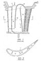
- Vanes currently used in gas turbine engines use a three pass serpentine cooling passageway 10 such as that shown in FIGS. 1 and 2 to convectively cool a mid-body region of the airfoil 11. Cooling fluid enters the passageway 10 through a fluid inlet 12 and travels through the inlet channel 14, then around a first turn 16 into an intermediate channel 18, then around a second turn 20, and through an outlet channel 22. Heat transfer tests have shown that this configuration can be inadequate and cooling losses may be encountered due to poorly developed flow structure in the channels 14 and 18 and large regions of flow separation downstream of the first turn 16, extending almost to the second turn 20. These issues can be attributed to both the low flow rate per unit flow area, and to the very low aspect ratio in the channel 18 with long rough walls and short divider walls.
- a cooling passageway which has an improved flow structure and improved heat transfer properties.
- a cooling passageway for use in an airfoil portion of a turbine engine component having a pressure side wall and a suction side wall.
- the cooling passageway broadly comprises a serpentine flow passageway through which a cooling fluid flows, which passageway has an inlet through which cooling fluid is introduced into the passageway, an inlet channel, an intermediate channel, and an outlet channel, and a divider rib extending from a location in the inlet channel to a termination in the intermediate channel.
- a turbine engine component broadly comprises an airfoil portion having a suction side wall and a pressure side wall, and a serpentine cooling passageway within the airfoil portion located between the suction side wall and the pressure side wall.
- the serpentine cooling passageway has an inlet channel, an intermediate channel, a first turn fluidly connecting the inlet channel to the intermediate channel, an outlet channel, and a second turn fluidly connecting the intermediate channel to the outlet channel.
- the inlet channel communicates with a source of cooling fluid via a fluid inlet.
- the cooling passageway further has means for dividing the flow within the inlet channel and a portion of the intermediate channel into two flow streams for providing improved heat transfer coefficients.
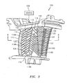
- the passageway 110 has a serpentine configuration with a fluid inlet 112, an inlet channel 114, a first turn 116, an intermediate channel 118, a second turn 120, and an outlet channel 122.
- the fluid inlet 112 may communicate with a source 109 of cooling fluid.
- the passageway 110 further has a U-shaped divider rib 124 which may extend from the inlet 112 to divide the channel 114 into a first channel 114A and a second channel 114B.
- the U-shaped divider rib 124 allows a split of the cooling fluid entering the passageway 110 into two flow streams to be more easily controlled and to be more uniformly distributed.
- the U-shaped or arcuately shaped portion 126 of the divider rib 124 assists in guiding the cooling fluid around the first turn 116 in each of the channels 114A and 114B.
- the U-shaped divider rib 124 extends into the intermediate channel 118 and divides at least a portion of the intermediate channel 118 into a first trip strip channel 118A and a second trip strip channel 118B.
- Each of the channels 118A, 118B, 114A, and 114B has a plurality of spaced apart, angled trip strips 130 for creating a desirable double vortex flow structure within the cooling fluid flow streams in the channels 118A and 118B which improves heat transfer coefficients.
- the trip strips 130 are staggered one half pitch apart from the suction side wall 132 to the pressure side wall 134.
- the term "pitch" is defined as the radial distance between adjacent trip strips
- the presence of the U-shaped divider rib 124 in the intermediate channel 118 provides each of the channels 118A and 118B with an improved aspect ratio.
- aspect ratio means the length of the channel divided by the height. It has been found that as a result of the presence of the U-shaped divider rib 124 in the intermediate channel 118, the aforementioned double vortex flow structure induced by the trip strips 130 begins to develop sooner and generates higher heat transfer coefficients earlier in the passageway 110.
- the U-shaped divider rib 124 has a termination 125 upstream of the second turn 120.
- the location of the termination 125 is at a point where the flow of the cooling fluid in intermediate channel 118 is fully developed. It has been found that there is minimal cooling flow separation at the downstream termination 125 of the U-shaped divider rib 124. In this location, the two flow streams in channels 118A and 118B are well developed and nearly parallel. Any loss at the junction of the two flow streams in the vicinity of the termination 125 is quite small.
- the outlet channel 122 may also be provided with a plurality of spaced apart, angled trip strips 130.
- the trip strips 130 are staggered one half pitch apart from suction side wall 132 to pressure side wall 134.
- the cooling flow may exit the outlet channel 122 in any suitable manner known in the art such as through a series of film cooling holes (not shown) or through a plurality of cooling passageways (not shown) in the trailing edge portion 113 of the airfoil 111.
- the U-shaped divider rib 124 may be started at a location several hydraulic diameters downstream of the inlet 112 such as 0.5 to 5 hydraulic diameters.
- hydraulic diameter is approximately 4 times the area of the inlet channel divided by the wetted perimeter of the inlet channel. Placing the beginning of the U-shaped diameter rib 124 in such a location reduces the head loss associated with the split of the incoming cooling fluid flow.
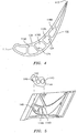
- a metering plate 140 may be welded or brazed.
- the metering plate 140 may be provided with at least two flow metering holes 142 and 144 of a desired dimension and configuration that overlap the channels 114A and 114B formed by the divider rib 124. If desired, a third flow-metering hole 146 may be provided in the plate 140. The hole 146 may communicate with the leading edge flow inlet 148.
- Turbine engine components which utilize the enhanced serpentine cooling passageway of the present invention may have both a low cooling air supply pressure and a small cooling flow allocation.
- the addition of the U-shaped divider rib 124 has several heat transfer benefits and will ensure the success of this configuration without changing the cooling air supply pressure or flow rate.
- the cavity area is reduced by the size of the divider rib 124, improving the amount of cooling flow per unit area.
- the aspect ratio of the trip strip channels in the intermediate channels 114 and 118 is dramatically improved, allowing a desirable double vortex structure intended by the angled trip strips 130 to develop quickly. Additionally, the flow around the first turn 116 is completely guided, controlling the loss around the first turn 116, forcing the flow to distribute more evenly around the turn 116, and eliminating flow separation downstream of the turn 116.
- a serpentine cooling passageway with a U-shaped divider rib in accordance with the present invention will be superior to a five pass serpentine solution in convective applications where the available cooling supply flow rate and pressure are limited due to the lower level of additional pressure loss. It also allows targeting of internal heat transfer coefficients to a second passage of the inner or outer loop, where a five pass serpentine in satisfying the continual convergence criteria is more limited.
- the U-shaped rib of the present invention is also preferred to simple divided passages due to both the improved flow structure around the turn and the elimination of the loss associated with dividing a channel in a region with non-negligible Mach number flow, and/or where the flow is not well developed. To achieve full benefit, care must be taken to configure the inner and outer turns properly.
- the U-shaped divider rib 124 allows tailoring of internal heat transfer coefficients to the inner or outer channel, offering improved design flexibility.
- the improvements provided by the cooling passageway of the present invention will lead to greatly increased airfoil oxidation and thermal mechanical fatigue (TMF) cracking life in the mid-body of the airfoil portion of the turbine engine component.
- TMF thermal mechanical fatigue
Landscapes
- Engineering & Computer Science (AREA)
- Mechanical Engineering (AREA)
- General Engineering & Computer Science (AREA)
- Turbine Rotor Nozzle Sealing (AREA)
Applications Claiming Priority (1)
| Application Number | Priority Date | Filing Date | Title |
|---|---|---|---|
| US11/391,781 US7445432B2 (en) | 2006-03-28 | 2006-03-28 | Enhanced serpentine cooling with U-shaped divider rib |
Publications (3)
| Publication Number | Publication Date |
|---|---|
| EP1849961A2 true EP1849961A2 (de) | 2007-10-31 |
| EP1849961A3 EP1849961A3 (de) | 2011-08-03 |
| EP1849961B1 EP1849961B1 (de) | 2019-01-02 |
Family
ID=38007200
Family Applications (1)
| Application Number | Title | Priority Date | Filing Date |
|---|---|---|---|
| EP07251298.1A Active EP1849961B1 (de) | 2006-03-28 | 2007-03-27 | Gasturbinennlaufschaufel mit Serpentinenkühlung und Strömungsteiler |
Country Status (3)
| Country | Link |
|---|---|
| US (1) | US7445432B2 (de) |
| EP (1) | EP1849961B1 (de) |
| JP (1) | JP2007263112A (de) |
Cited By (4)
| Publication number | Priority date | Publication date | Assignee | Title |
|---|---|---|---|---|
| WO2009109462A1 (de) * | 2008-03-07 | 2009-09-11 | Alstom Technology Ltd | Schaufel für eine gasturbine |
| WO2009118245A1 (de) * | 2008-03-28 | 2009-10-01 | Alstom Technology Ltd | Leitschaufel für eine gasturbine sowie gasturbine mit einer solchen leitschaufel |
| EP2093376A3 (de) * | 2008-01-22 | 2012-11-14 | United Technologies Corporation | Eine Turbinenleitschaufel, die entsprechende Kühlkanalanordnung und das Verfahren zum Kühlen dieser Leitschaufel |
| CN111648830A (zh) * | 2020-05-14 | 2020-09-11 | 西安交通大学 | 一种用于涡轮动叶后部的内冷带肋通道 |
Families Citing this family (21)
| Publication number | Priority date | Publication date | Assignee | Title |
|---|---|---|---|---|
| US8172533B2 (en) | 2008-05-14 | 2012-05-08 | United Technologies Corporation | Turbine blade internal cooling configuration |
| US8177507B2 (en) | 2008-05-14 | 2012-05-15 | United Technologies Corporation | Triangular serpentine cooling channels |
| JP4841678B2 (ja) * | 2010-04-15 | 2011-12-21 | 川崎重工業株式会社 | ガスタービンのタービン静翼 |
| US8821111B2 (en) * | 2010-12-14 | 2014-09-02 | Siemens Energy, Inc. | Gas turbine vane with cooling channel end turn structure |
| US8882461B2 (en) | 2011-09-12 | 2014-11-11 | Honeywell International Inc. | Gas turbine engines with improved trailing edge cooling arrangements |
| BR112014016003A8 (pt) | 2011-12-29 | 2017-07-04 | Gen Electric | circuito de resfriamento de aerofólio e aerofólio para uso em um motor de turbina a gás |
| US9157329B2 (en) | 2012-08-22 | 2015-10-13 | United Technologies Corporation | Gas turbine engine airfoil internal cooling features |
| US9995148B2 (en) | 2012-10-04 | 2018-06-12 | General Electric Company | Method and apparatus for cooling gas turbine and rotor blades |
| US9850762B2 (en) | 2013-03-13 | 2017-12-26 | General Electric Company | Dust mitigation for turbine blade tip turns |
| EP3114322B1 (de) | 2014-03-05 | 2018-08-22 | Siemens Aktiengesellschaft | Turbinenschaufel |
| US9957816B2 (en) | 2014-05-29 | 2018-05-01 | General Electric Company | Angled impingement insert |
| US10422235B2 (en) | 2014-05-29 | 2019-09-24 | General Electric Company | Angled impingement inserts with cooling features |
| US10364684B2 (en) | 2014-05-29 | 2019-07-30 | General Electric Company | Fastback vorticor pin |
| CA2950011C (en) | 2014-05-29 | 2020-01-28 | General Electric Company | Fastback turbulator |
| WO2016025054A2 (en) | 2014-05-29 | 2016-02-18 | General Electric Company | Engine components with cooling features |
| CN106536858B (zh) | 2014-07-24 | 2019-01-01 | 西门子公司 | 具有顺翼展延伸流阻断器的涡轮翼型件冷却系统 |
| US10280785B2 (en) | 2014-10-31 | 2019-05-07 | General Electric Company | Shroud assembly for a turbine engine |
| US10233775B2 (en) | 2014-10-31 | 2019-03-19 | General Electric Company | Engine component for a gas turbine engine |
| US10196910B2 (en) * | 2015-01-30 | 2019-02-05 | Rolls-Royce Corporation | Turbine vane with load shield |
| US10060272B2 (en) | 2015-01-30 | 2018-08-28 | Rolls-Royce Corporation | Turbine vane with load shield |
| US10968746B2 (en) * | 2018-09-14 | 2021-04-06 | Raytheon Technologies Corporation | Serpentine turn cover for gas turbine stator vane assembly |
Family Cites Families (12)
| Publication number | Priority date | Publication date | Assignee | Title |
|---|---|---|---|---|
| US4753575A (en) * | 1987-08-06 | 1988-06-28 | United Technologies Corporation | Airfoil with nested cooling channels |
| US5700131A (en) * | 1988-08-24 | 1997-12-23 | United Technologies Corporation | Cooled blades for a gas turbine engine |
| US5403159A (en) * | 1992-11-30 | 1995-04-04 | United Technoligies Corporation | Coolable airfoil structure |
| JPH07233702A (ja) * | 1994-02-23 | 1995-09-05 | Mitsubishi Heavy Ind Ltd | ガスタービン中空動翼 |
| JPH10280904A (ja) * | 1997-04-01 | 1998-10-20 | Mitsubishi Heavy Ind Ltd | ガスタービン冷却動翼 |
| CA2262701C (en) * | 1997-06-06 | 2003-02-18 | Mitsubishi Heavy Industries, Ltd. | Gas turbine blade |
| EP1223308B1 (de) * | 2000-12-16 | 2007-01-24 | ALSTOM Technology Ltd | Komponente einer Strömungsmaschine |
| JP4649763B2 (ja) * | 2001-04-05 | 2011-03-16 | 株式会社Ihi | タービン翼の冷却空気調整構造 |
| US6672836B2 (en) * | 2001-12-11 | 2004-01-06 | United Technologies Corporation | Coolable rotor blade for an industrial gas turbine engine |
| EP1577497A1 (de) * | 2004-03-01 | 2005-09-21 | ALSTOM Technology Ltd | Strömungsmaschinenschaufel mit interner Kühlung |
| US7118325B2 (en) * | 2004-06-14 | 2006-10-10 | United Technologies Corporation | Cooling passageway turn |
| US7189060B2 (en) * | 2005-01-07 | 2007-03-13 | Siemens Power Generation, Inc. | Cooling system including mini channels within a turbine blade of a turbine engine |
-
2006
- 2006-03-28 US US11/391,781 patent/US7445432B2/en active Active
-
2007
- 2007-03-26 JP JP2007078071A patent/JP2007263112A/ja active Pending
- 2007-03-27 EP EP07251298.1A patent/EP1849961B1/de active Active
Cited By (7)
| Publication number | Priority date | Publication date | Assignee | Title |
|---|---|---|---|---|
| EP2093376A3 (de) * | 2008-01-22 | 2012-11-14 | United Technologies Corporation | Eine Turbinenleitschaufel, die entsprechende Kühlkanalanordnung und das Verfahren zum Kühlen dieser Leitschaufel |
| WO2009109462A1 (de) * | 2008-03-07 | 2009-09-11 | Alstom Technology Ltd | Schaufel für eine gasturbine |
| US8182225B2 (en) | 2008-03-07 | 2012-05-22 | Alstomtechnology Ltd | Blade for a gas turbine |
| WO2009118245A1 (de) * | 2008-03-28 | 2009-10-01 | Alstom Technology Ltd | Leitschaufel für eine gasturbine sowie gasturbine mit einer solchen leitschaufel |
| US8801366B2 (en) | 2008-03-28 | 2014-08-12 | Alstom Technology Ltd. | Stator blade for a gas turbine and gas turbine having same |
| CN111648830A (zh) * | 2020-05-14 | 2020-09-11 | 西安交通大学 | 一种用于涡轮动叶后部的内冷带肋通道 |
| CN111648830B (zh) * | 2020-05-14 | 2021-04-20 | 西安交通大学 | 一种用于涡轮动叶后部的内冷带肋通道 |
Also Published As
| Publication number | Publication date |
|---|---|
| EP1849961B1 (de) | 2019-01-02 |
| US7445432B2 (en) | 2008-11-04 |
| JP2007263112A (ja) | 2007-10-11 |
| EP1849961A3 (de) | 2011-08-03 |
| US20070231138A1 (en) | 2007-10-04 |
Similar Documents
| Publication | Publication Date | Title |
|---|---|---|
| EP1849961B1 (de) | Gasturbinennlaufschaufel mit Serpentinenkühlung und Strömungsteiler | |
| US7997868B1 (en) | Film cooling hole for turbine airfoil | |
| US10876413B2 (en) | Turbine airfoils with micro cooling features | |
| CN103119247B (zh) | 燃气涡轮叶片 | |
| US9382804B2 (en) | Cooled blade for a gas turbine | |
| CN102089498B (zh) | 用于燃气涡轮机的涡轮机叶片和用于制造这样的涡轮机叶片的型芯 | |
| US8985940B2 (en) | Turbine cooling apparatus | |
| EP2325440B1 (de) | Turbinenschaufel mit serpentinenförmigen Mikrokühlkanälen | |
| CN101779001B (zh) | 燃气轮机的叶片冷却结构 | |
| EP2107215A1 (de) | Gasturbinenschaufel | |
| EP1561902B1 (de) | Turbinenschaufel mit Turbulatoren | |
| RU2531839C2 (ru) | Газовая турбина | |
| US7762775B1 (en) | Turbine airfoil with cooled thin trailing edge | |
| KR20050074303A (ko) | 팬형 후단 에지 티어드롭 어레이 | |
| JP5189406B2 (ja) | ガスタービン翼およびこれを備えたガスタービン | |
| EP3399149A1 (de) | Umlenkkappen für schaufeln in gasturbinentriebwerken | |
| EP2752554A1 (de) | Schaufel für eine Turbomaschine | |
| US20090104029A1 (en) | Flow Machine | |
| JP6669440B2 (ja) | 翼の冷却回路の供給ダクト、排出ダクト、および関連冷却構造 | |
| US11499436B2 (en) | Turbine engine blade with improved cooling | |
| JP5496263B2 (ja) | ガスタービン翼およびこれを備えたガスタービン |
Legal Events
| Date | Code | Title | Description |
|---|---|---|---|
| PUAI | Public reference made under article 153(3) epc to a published international application that has entered the european phase |
Free format text: ORIGINAL CODE: 0009012 |
|
| AK | Designated contracting states |
Kind code of ref document: A2 Designated state(s): AT BE BG CH CY CZ DE DK EE ES FI FR GB GR HU IE IS IT LI LT LU LV MC MT NL PL PT RO SE SI SK TR |
|
| AX | Request for extension of the european patent |
Extension state: AL BA HR MK YU |
|
| PUAL | Search report despatched |
Free format text: ORIGINAL CODE: 0009013 |
|
| AK | Designated contracting states |
Kind code of ref document: A3 Designated state(s): AT BE BG CH CY CZ DE DK EE ES FI FR GB GR HU IE IS IT LI LT LU LV MC MT NL PL PT RO SE SI SK TR |
|
| AX | Request for extension of the european patent |
Extension state: AL BA HR MK RS |
|
| 17P | Request for examination filed |
Effective date: 20120202 |
|
| AKX | Designation fees paid |
Designated state(s): DE GB |
|
| 17Q | First examination report despatched |
Effective date: 20150908 |
|
| RAP1 | Party data changed (applicant data changed or rights of an application transferred) |
Owner name: UNITED TECHNOLOGIES CORPORATION |
|
| STAA | Information on the status of an ep patent application or granted ep patent |
Free format text: STATUS: EXAMINATION IS IN PROGRESS |
|
| GRAP | Despatch of communication of intention to grant a patent |
Free format text: ORIGINAL CODE: EPIDOSNIGR1 |
|
| STAA | Information on the status of an ep patent application or granted ep patent |
Free format text: STATUS: GRANT OF PATENT IS INTENDED |
|
| INTG | Intention to grant announced |
Effective date: 20180718 |
|
| GRAS | Grant fee paid |
Free format text: ORIGINAL CODE: EPIDOSNIGR3 |
|
| GRAA | (expected) grant |
Free format text: ORIGINAL CODE: 0009210 |
|
| STAA | Information on the status of an ep patent application or granted ep patent |
Free format text: STATUS: THE PATENT HAS BEEN GRANTED |
|
| REG | Reference to a national code |
Ref country code: DE Ref legal event code: R081 Ref document number: 602007057306 Country of ref document: DE Owner name: RAYTHEON TECHNOLOGIES CORPORATION (N.D.GES.D.S, US Free format text: FORMER OWNER: UNITED TECHNOLOGIES INC., HARTFORD, CONN., US |
|
| AK | Designated contracting states |
Kind code of ref document: B1 Designated state(s): DE GB |
|
| REG | Reference to a national code |
Ref country code: GB Ref legal event code: FG4D |
|
| REG | Reference to a national code |
Ref country code: DE Ref legal event code: R096 Ref document number: 602007057306 Country of ref document: DE |
|
| REG | Reference to a national code |
Ref country code: DE Ref legal event code: R097 Ref document number: 602007057306 Country of ref document: DE |
|
| PLBE | No opposition filed within time limit |
Free format text: ORIGINAL CODE: 0009261 |
|
| STAA | Information on the status of an ep patent application or granted ep patent |
Free format text: STATUS: NO OPPOSITION FILED WITHIN TIME LIMIT |
|
| 26N | No opposition filed |
Effective date: 20191003 |
|
| REG | Reference to a national code |
Ref country code: DE Ref legal event code: R081 Ref document number: 602007057306 Country of ref document: DE Owner name: RAYTHEON TECHNOLOGIES CORPORATION (N.D.GES.D.S, US Free format text: FORMER OWNER: UNITED TECHNOLOGIES CORPORATION, FARMINGTON, CONN., US Ref country code: DE Ref legal event code: R081 Ref document number: 602007057306 Country of ref document: DE Owner name: RTX CORPORATION (N.D.GES.D. STAATES DELAWARE),, US Free format text: FORMER OWNER: UNITED TECHNOLOGIES CORPORATION, FARMINGTON, CONN., US |
|
| P01 | Opt-out of the competence of the unified patent court (upc) registered |
Effective date: 20230519 |
|
| PGFP | Annual fee paid to national office [announced via postgrant information from national office to epo] |
Ref country code: DE Payment date: 20250218 Year of fee payment: 19 |
|
| PGFP | Annual fee paid to national office [announced via postgrant information from national office to epo] |
Ref country code: GB Payment date: 20250221 Year of fee payment: 19 |
|
| REG | Reference to a national code |
Ref country code: DE Ref legal event code: R081 Ref document number: 602007057306 Country of ref document: DE Owner name: RTX CORPORATION (N.D.GES.D. STAATES DELAWARE),, US Free format text: FORMER OWNER: RAYTHEON TECHNOLOGIES CORPORATION (N.D.GES.D.STAATES DELAWARE), ARLINGTON, VA, US |