EP1849974A2 - Tailcone-Resonator für ein Turbinentriebwerk - Google Patents
Tailcone-Resonator für ein Turbinentriebwerk Download PDFInfo
- Publication number
- EP1849974A2 EP1849974A2 EP07250806A EP07250806A EP1849974A2 EP 1849974 A2 EP1849974 A2 EP 1849974A2 EP 07250806 A EP07250806 A EP 07250806A EP 07250806 A EP07250806 A EP 07250806A EP 1849974 A2 EP1849974 A2 EP 1849974A2
- Authority
- EP
- European Patent Office
- Prior art keywords
- resonator
- panel
- aperture
- mounting flange
- flange
- Prior art date
- Legal status (The legal status is an assumption and is not a legal conclusion. Google has not performed a legal analysis and makes no representation as to the accuracy of the status listed.)
- Granted
Links
Images


Classifications
-
- F—MECHANICAL ENGINEERING; LIGHTING; HEATING; WEAPONS; BLASTING
- F01—MACHINES OR ENGINES IN GENERAL; ENGINE PLANTS IN GENERAL; STEAM ENGINES
- F01D—NON-POSITIVE DISPLACEMENT MACHINES OR ENGINES, e.g. STEAM TURBINES
- F01D25/00—Component parts, details, or accessories, not provided for in, or of interest apart from, other groups
- F01D25/30—Exhaust heads, chambers, or the like
-
- F—MECHANICAL ENGINEERING; LIGHTING; HEATING; WEAPONS; BLASTING
- F02—COMBUSTION ENGINES; HOT-GAS OR COMBUSTION-PRODUCT ENGINE PLANTS
- F02C—GAS-TURBINE PLANTS; AIR INTAKES FOR JET-PROPULSION PLANTS; CONTROLLING FUEL SUPPLY IN AIR-BREATHING JET-PROPULSION PLANTS
- F02C5/00—Gas-turbine plants characterised by the working fluid being generated by intermittent combustion
- F02C5/10—Gas-turbine plants characterised by the working fluid being generated by intermittent combustion the working fluid forming a resonating or oscillating gas column, i.e. the combustion chambers having no positively actuated valves, e.g. using Helmholtz effect
-
- F—MECHANICAL ENGINEERING; LIGHTING; HEATING; WEAPONS; BLASTING
- F02—COMBUSTION ENGINES; HOT-GAS OR COMBUSTION-PRODUCT ENGINE PLANTS
- F02K—JET-PROPULSION PLANTS
- F02K1/00—Plants characterised by the form or arrangement of the jet pipe or nozzle; Jet pipes or nozzles peculiar thereto
- F02K1/78—Other construction of jet pipes
- F02K1/82—Jet pipe walls, e.g. liners
- F02K1/827—Sound absorbing structures or liners
-
- F—MECHANICAL ENGINEERING; LIGHTING; HEATING; WEAPONS; BLASTING
- F02—COMBUSTION ENGINES; HOT-GAS OR COMBUSTION-PRODUCT ENGINE PLANTS
- F02K—JET-PROPULSION PLANTS
- F02K3/00—Plants including a gas turbine driving a compressor or a ducted fan
- F02K3/08—Plants including a gas turbine driving a compressor or a ducted fan with supplementary heating of the working fluid; Control thereof
- F02K3/10—Plants including a gas turbine driving a compressor or a ducted fan with supplementary heating of the working fluid; Control thereof by after-burners
-
- F—MECHANICAL ENGINEERING; LIGHTING; HEATING; WEAPONS; BLASTING
- F23—COMBUSTION APPARATUS; COMBUSTION PROCESSES
- F23R—GENERATING COMBUSTION PRODUCTS OF HIGH PRESSURE OR HIGH VELOCITY, e.g. GAS-TURBINE COMBUSTION CHAMBERS
- F23R3/00—Continuous combustion chambers using liquid or gaseous fuel
-
- F—MECHANICAL ENGINEERING; LIGHTING; HEATING; WEAPONS; BLASTING
- F05—INDEXING SCHEMES RELATING TO ENGINES OR PUMPS IN VARIOUS SUBCLASSES OF CLASSES F01-F04
- F05D—INDEXING SCHEME FOR ASPECTS RELATING TO NON-POSITIVE-DISPLACEMENT MACHINES OR ENGINES, GAS-TURBINES OR JET-PROPULSION PLANTS
- F05D2260/00—Function
- F05D2260/96—Preventing, counteracting or reducing vibration or noise
-
- F—MECHANICAL ENGINEERING; LIGHTING; HEATING; WEAPONS; BLASTING
- F05—INDEXING SCHEMES RELATING TO ENGINES OR PUMPS IN VARIOUS SUBCLASSES OF CLASSES F01-F04
- F05D—INDEXING SCHEME FOR ASPECTS RELATING TO NON-POSITIVE-DISPLACEMENT MACHINES OR ENGINES, GAS-TURBINES OR JET-PROPULSION PLANTS
- F05D2260/00—Function
- F05D2260/99—Ignition, e.g. ignition by warming up of fuel or oxidizer in a resonant acoustic cavity
-
- F—MECHANICAL ENGINEERING; LIGHTING; HEATING; WEAPONS; BLASTING
- F23—COMBUSTION APPARATUS; COMBUSTION PROCESSES
- F23R—GENERATING COMBUSTION PRODUCTS OF HIGH PRESSURE OR HIGH VELOCITY, e.g. GAS-TURBINE COMBUSTION CHAMBERS
- F23R2900/00—Special features of, or arrangements for continuous combustion chambers; Combustion processes therefor
- F23R2900/00014—Reducing thermo-acoustic vibrations by passive means, e.g. by Helmholtz resonators
Definitions
- the invention relates to turbine engines. More particularly, the invention relates to tailcone resonator arrays.
- One aspect of the invention involves a turbine engine resonator comprising a panel and a vessel.
- the panel is along a flow path within the engine and has an aperture.
- the vessel has a mounting flange secured to the panel.
- the flange has an aperture mated to the aperture of the panel.
- the vessel has a body secured to the mounting flange with an interior of the body in communication with the flange aperture.
- a first portion of the panel extends into the mounting flange aperture and may redirect a leakage flow, if any, to limit an effect of leakage upon resonator performance.
- a turbine engine resonator comprising a panel and a vessel.
- the panel is along a flow path within the engine and has an aperture.
- the vessel has a mounting flange secured to the panel.
- the flange has an aperture mated to the aperture of the panel.
- the vessel has a body secured to the mounting flange with an interior of the body in communication with the flange aperture.
- the panel has a seat circumscribing the panel aperture.
- the mounting flange has a seat circumscribing the mounting flange aperture.
- the mounting flange has a pair of mounting ears secured to the panel by an associated fastener to hold the mounting flange seat engaged to the panel seat by an interference mounting.
- a turbine engine having a case.
- a centerbody is within the case and separated from the case by a core flowpath.
- a circumferential array of augmentor vanes extend between the centerbody and case.
- a circumferential array of resonators are within the centerbody and each has a port open to the core flowpath.
- Each said resonator comprises a resonator body having a neck and an enlarged main body inboard of the neck, main body having a convex first circumferential side and a concave second circumferential side converging inboard, each first circumferential side nested with the second adjacent side of a first adjacent one of the resonators and each second circumferential side nested with the first adjacent side of a second adjacent one of the resonators.
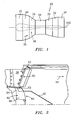
- FIG. 1 shows an exemplary engine 20 having a central longitudinal axis 500.
- the exemplary engine includes a number of sections: a fan section 22; a low pressure compressor section 24; a high pressure compressor section 26; a combustor section 28; a high pressure turbine section 30; a low pressure turbine section 32; and an augmentor 34.
- a first airflow 36 is driven along a core flowpath 38 through the various sections.
- An additional bypass airflow may be driven along a bypass flowpath (not shown).
- FIG. 2 shows a tailcone 40 forming the downstream end of a centerbody within the core flowpath 38 inboard of a turbine exhaust case 42.
- a circular array of vanes 50 of the augmentor radially span between the centerbody and the turbine exhaust case 42.
- a nozzle (not shown) may be downstream of the turbine exhaust case.
- the centerbody periphery is formed by an array of inner diameter (ID) panels 52.
- ID inner diameter
- the exemplary panels 52 are arcuate to correspond to the shape and orientation of the vanes.
- Trailing edge (TE) box portions of the vanes 52 contain fuel spraybars (not shown) for introducing fuel to the initial exhaust flow 54 (the combusted airflow 36) passing over/between the vanes.
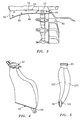
- the exemplary ID panels 52 (FIG. 3) have leading and trailing edges 60 and 62 and first and second circumferential sides 64 and 66.
- the panels 52 have inboard and outboard surfaces 68 and 70. Relatively near the trailing edge 62, each panel 52 includes an aperture 72 between the inboard and outboard surfaces 68 and 70.
- the apertures 72 define ports for Helmholtz resonators 80.
- the exemplary resonators 80 (FIG. 2) include an associated resonator vessel 82 mounted inboard of the associated panel 52.
- the exemplary vessel 82 includes a body having an outboard neck 84 and an inboard main portion 86.
- the exemplary neck 84 extends from a forward/upstream end of the exemplary main portion 86. The remainder of the main portion extends downstream partially into the interior of the tailcone 40.
- the exemplary vessel 82 comprises a pair of sheet metal stampings welded to each other and closed at their inboard ends by a cast or machined ID bracket 90 (FIGS. 4-6). At their outboard ends, the stampings are secured to a neck flange 92 mounting the resonator vessel 82 to the ID panel 52.
- Each exemplary bracket 90 includes, near the rear/trailing end thereof, an apertured mounting ear 100. The ears 100 are bolted to associated bolt holes of a central mounting ring 102 (FIG. 7) to integrate the various resonator vessels into a rigid assembly.
- FIG. 8 shows a relationship between the ID panels 52 and the adjacent vanes 50.
- Each vane 50 has a first side 120 and a second side 122.
- each vane side may typically include one or more streamwise panels.
- An exemplary first side panel includes a generally radially and streamwise-extending sidewall 130 and a generally circumferential and streamwise-extending flange 132 at an inboard end of the panel and projecting circumferentially outward from the vane.
- the second side panel has a sidewall 134 and a flange 136. The exemplary flanges 132 and 136 are captured beneath side portions of the adjacent ID panel 52.
- a first portion 140 along the first side 64 of the ID panel captures the flange 136 of the adjacent second panel of one adjacent vane while a side portion 142 along the second side 66 captures the flange 132 of the first panel of the previous vane (viewed counterclockwise when looking aft-to-fore).
- a fastener array along the portions 140 and 142 may secure those portions to the associated flanges 136 and 132 with the underside of the portion 140 or 142 compressingly engaged to the outboard face of the flange 136 or 132 (optionally with an intervening seal/gasket).
- the exemplary joint between the resonator vessel and ID panel comprises a hard interference fit maintained by a pair of fasteners (e.g., bolts).
- the exemplary flange 92 includes an apertured upstream mounting ear 150 (FIG. 9) and an apertured downstream mounting ear 152. These ears align with corresponding apertures in the ID panel 52 to receive bolts 160 and 162 (e.g., having heads recessed approximately flush to the panel outboard surface and shaft receiving nuts along the ear undersides).
- the exemplary flange 92 includes an outwardly protruding boss whose rim forms a seat 170 surrounding an aperture defined by an aperture surface 172.
- the exemplary surface 172 is smooth and continuous with an interior surface 174 of the resonator body.
- a port 176 is formed in the ID panel 52.
- a surface 178 extends radially inward from the port 176 to an inboard rim 180.
- a terminal portion of the surface 178 is generally straight in section (i.e., not diverging or converging).
- the rim 180 is at the inboard end of a lip or collar portion 182 of the panel.
- the collar portion 182 extends inward from an external shoulder 184 and has an exterior surface 186.
- a thicker collar or boss portion 188 may be located outboard of the shoulder 184.
- the shoulder 184 forms a mating seat engaging the flange seat 170.
- the collar exterior surface 186 is locally spaced apart from the surface 172 by a gap 190.
- the exemplary gap 190 has an overall length L G and a characteristic thickness (e.g., a median thickness T G ).
- An exemplary L G is 0.171 (nominal) +/- 0.008 inch. Broader L G ranges are 0.15-0.30 inch and 0.16-0.20 inch.
- An exemplary T G is 0.045 (nominal) +/- 0.043 inch. Broader T G ranges are 0.001-0.15 inch and 0.002-0.12 inch.
- gaps 200 and 202 In a relaxed condition (e.g., before tightening of the bolts 160 and 162), there are gaps 200 and 202 between the ear outboard surfaces and the mating surfaces of the inboard face of the panel (or of any intervening components such as a washer or spacer). In the relaxed condition, there is contact between the seats 170 and 184.
- Exemplary gaps 200 and 202 have thicknesses of 0.014 inch and 0.009 inch.
- the specific gaps will be influenced by a variety of specific engineering details of the particular flange 92 and ID panel 52. Generally, exemplary gaps may be 0.06-0.25 inch. However, other values are possible.
- the result in tightening is to close the gaps 200 and 202 and elastically deform the flange 92 between the bolted portions of the ears and the collar.
- This the gaps create a hard interference fit with metal-to-metal contact at the seats 170 and 84 without an intervening rope seal, gasket, or the like.
- the bolting tension and flange elastic deformation maintain the engagement force between the seats.
- Exemplary interference fit is sufficiently robust to reduce and preferably largely eliminate leakage of the wide operating envelope. However, some leakage may be inevitable.
- the depending collar 182 acts to redirect any leakage flow radially inward along the annular gap 190.
- this flow may be discharged into the resonator with more of a radial inward component than a component normal to the wall of the neck/throat. This redirection may reduce a fluidic throat effect which might, for example, tend to vary the tuning of the resonator responsive to the leakage flow.
- first and second side panels 220 and 222 are respectively seen.
- the first panel 220 is generally outwardly convex whereas the second panel 222 is generally outwardly concave.
- the panels generally converge inboard toward each other.
- the convex/concave combination permits internesting of the resonators in the resonator array. The this provides a compromise of traditional Helmholtz Resonator shape to accommodate the existing turbine exhaust case and augmentor hardware while still providing effective resonator volume and length dimensions with in the resonator.
- the inventive resonator may be implemented in the remanufacture or reengineering of a baseline engine or configuration thereof.
- the baseline configuration may include an existing tailcone resonator or may lack a tailcone resonator. If the baseline configuration includes a resonator, the revised configuration may provide one or both of enhanced leakage control and reduced sensitivity to leakage.
- FIG. 10 shows the port area of an exemplary baseline resonator 400.
- the port 402 is formed in an ID panel 404 mated to a resonator mounting flange 406.
- the panel 404 Surrounding the port, the panel 404 includes a depending collar 410 having an interior surface 412 and extending to an inboard rim 414.
- the inboard rim 414 butts against a seating surface 416 of the flange 406 surrounding an aperture surface 418 of the flange.
- the exemplary rim 414 has a recess accommodating a rope seal 420.
- the exemplary surfaces 412 and 418 are aligned so as to present a smooth continuous port surface.
- the depending panel collar functions to redirect any leakage flow 430 (FIG. 11) off-normal to the resonator throat (radially inward in the exemplary resonator). This may reduce the degradation associated with a given leakage amount. Additionally, the hard interference seal may further limit the amount of leakage.
- FIGS. 12 and 13 show, respectively for the baseline and reengineered resonators, ratios of cavity pressure to face/port pressure against frequency.
- Each graph includes three traces at three different nominal values of ⁇ P/P (the pressure difference across the resonator normalized by the supply pressure): 0, 10% and 20%.
- Typical engine operating AP/P are in excess of 20% (also designated as a liner pressure ratio (LPR) in excess of 1.20).
- LPR liner pressure ratio
- test resonators may be used in the reengineering process by measuring performance for a variety shapes/dimensions/positions of the panel lip and its associated gap to optimize performance in view of any other applicable factors.
Landscapes
- Engineering & Computer Science (AREA)
- Mechanical Engineering (AREA)
- General Engineering & Computer Science (AREA)
- Chemical & Material Sciences (AREA)
- Combustion & Propulsion (AREA)
- Turbine Rotor Nozzle Sealing (AREA)
- Structures Of Non-Positive Displacement Pumps (AREA)
- Gasket Seals (AREA)
Priority Applications (1)
| Application Number | Priority Date | Filing Date | Title |
|---|---|---|---|
| EP12160989.5A EP2484881B1 (de) | 2006-04-27 | 2007-02-27 | Gasturbinen Heckkonusresonator |
Applications Claiming Priority (1)
| Application Number | Priority Date | Filing Date | Title |
|---|---|---|---|
| US11/412,756 US7552796B2 (en) | 2006-04-27 | 2006-04-27 | Turbine engine tailcone resonator |
Publications (3)
| Publication Number | Publication Date |
|---|---|
| EP1849974A2 true EP1849974A2 (de) | 2007-10-31 |
| EP1849974A3 EP1849974A3 (de) | 2010-11-03 |
| EP1849974B1 EP1849974B1 (de) | 2012-03-28 |
Family
ID=38197765
Family Applications (2)
| Application Number | Title | Priority Date | Filing Date |
|---|---|---|---|
| EP07250806A Ceased EP1849974B1 (de) | 2006-04-27 | 2007-02-27 | Tailcone-Resonator für ein Turbinentriebwerk |
| EP12160989.5A Ceased EP2484881B1 (de) | 2006-04-27 | 2007-02-27 | Gasturbinen Heckkonusresonator |
Family Applications After (1)
| Application Number | Title | Priority Date | Filing Date |
|---|---|---|---|
| EP12160989.5A Ceased EP2484881B1 (de) | 2006-04-27 | 2007-02-27 | Gasturbinen Heckkonusresonator |
Country Status (3)
| Country | Link |
|---|---|
| US (1) | US7552796B2 (de) |
| EP (2) | EP1849974B1 (de) |
| JP (1) | JP2007298023A (de) |
Cited By (2)
| Publication number | Priority date | Publication date | Assignee | Title |
|---|---|---|---|---|
| EP3410014A1 (de) * | 2017-05-31 | 2018-12-05 | Ansaldo Energia S.p.A. | Plattenhalter für eine brennkammer einer gasturbine |
| CN115682033A (zh) * | 2021-07-28 | 2023-02-03 | 北京航空航天大学 | 防振燃烧室以及燃烧室防振方法 |
Families Citing this family (12)
| Publication number | Priority date | Publication date | Assignee | Title |
|---|---|---|---|---|
| US20070045042A1 (en) * | 2005-08-25 | 2007-03-01 | L&L Products, Inc. | Sound reduction system with sound reduction chamber |
| US7552796B2 (en) * | 2006-04-27 | 2009-06-30 | United Technologies Corporation | Turbine engine tailcone resonator |
| FR2905734B1 (fr) * | 2006-09-07 | 2012-07-13 | Airbus France | Dispositif permettant d'ameliorer l'efficacite des traitements acoustiques dans un conduit d'une motorisation d'aeronef |
| US7607287B2 (en) * | 2007-05-29 | 2009-10-27 | United Technologies Corporation | Airfoil acoustic impedance control |
| GB2452476B (en) * | 2007-07-19 | 2010-01-20 | Assystem Uk Ltd | Acoustic liner for gas turbine engine and method of manufacture thereof |
| US8713909B2 (en) | 2009-03-04 | 2014-05-06 | United Technologies Corporation | Elimination of unfavorable outflow margin |
| DE102009037956B4 (de) | 2009-08-18 | 2024-06-06 | MTU Aero Engines AG | Turbinenaustrittsgehäuse |
| US9200537B2 (en) | 2011-11-09 | 2015-12-01 | Pratt & Whitney Canada Corp. | Gas turbine exhaust case with acoustic panels |
| US8684130B1 (en) * | 2012-09-10 | 2014-04-01 | Alstom Technology Ltd. | Damping system for combustor |
| US9835112B2 (en) | 2014-02-10 | 2017-12-05 | MRA Systems Inc. | Thrust reverser cascade |
| CN107002999A (zh) * | 2014-12-01 | 2017-08-01 | 西门子公司 | 用于燃气涡轮发动机的具有可互换计量管的共振器 |
| US12339002B2 (en) | 2022-04-29 | 2025-06-24 | General Electric Company | Propulsion system for jet noise reduction |
Family Cites Families (55)
| Publication number | Priority date | Publication date | Assignee | Title |
|---|---|---|---|---|
| US2974744A (en) * | 1961-03-14 | Silencer | ||
| US1995542A (en) * | 1933-11-22 | 1935-03-26 | Haviland Arnold | Universal muffler coupling |
| GB442056A (en) * | 1934-03-24 | 1936-01-31 | Burgess Lab Inc C F | Improvements in apparatus for silencing gaseous currents |
| US2788803A (en) * | 1952-11-12 | 1957-04-16 | Solar Aircraft Co | Tail cone |
| US3187835A (en) * | 1960-02-08 | 1965-06-08 | Cloyd D Smith | Jet engine noise suppressor |
| DE1197279B (de) * | 1963-11-08 | 1965-07-22 | Gruenzweig & Hartmann | Schalldaempfer fuer den Bodenbetrieb von Strahltriebwerken |
| US3227240A (en) * | 1964-05-04 | 1966-01-04 | Gen Electric | Air mingling sound suppressor for jet engine |
| US3401774A (en) * | 1966-04-26 | 1968-09-17 | Alfred R. Krahn | Readily removable exhaust muffler for high vertical exhaust stacks |
| US3483698A (en) * | 1966-11-22 | 1969-12-16 | United Aircraft Corp | Combustion instability reduction device |
| US3820628A (en) * | 1972-10-02 | 1974-06-28 | United Aircraft Corp | Sound suppression means for rotating machinery |
| US3819007A (en) * | 1973-04-27 | 1974-06-25 | Lockheed Aircraft Corp | Controllable laminar sound absorptive structure |
| US4036452A (en) * | 1975-01-27 | 1977-07-19 | The Boeing Company | Retractable engine noise suppression system for over-the-wing jet aircraft |
| US4106587A (en) * | 1976-07-02 | 1978-08-15 | The United States Of America As Represented By The Administrator Of The National Aeronautics And Space Administration | Sound-suppressing structure with thermal relief |
| US4137992A (en) * | 1976-12-30 | 1979-02-06 | The Boeing Company | Turbojet engine nozzle for attenuating core and turbine noise |
| FR2376994A1 (fr) * | 1977-01-11 | 1978-08-04 | Snecma | Perfectionnements aux dispositifs a cavites resonnantes pour la reduction du bruit dans un conduit en presence d'un flux gazeux |
| US4473131A (en) * | 1982-08-06 | 1984-09-25 | Apx Group, Inc. | Threaded muffler nipple and bushing |
| US4475623A (en) * | 1982-09-20 | 1984-10-09 | Apx Group, Inc. | Universal muffler assembly |
| FR2696502B1 (fr) * | 1992-10-07 | 1994-11-04 | Snecma | Dispositif de post-combustion pour turbo réacteur double flux. |
| US4565260A (en) * | 1984-10-02 | 1986-01-21 | Maremont Corporation | Mechanical lock joint for vehicular exhaust system muffler and the like |
| JPS6317860U (de) * | 1986-07-17 | 1988-02-05 | ||
| FR2613773B1 (fr) * | 1987-04-08 | 1990-11-30 | Snecma | Panneau acoustique pour garniture insonorisante et turboreacteur comportant une telle garniture |
| US5393108A (en) * | 1993-06-11 | 1995-02-28 | Indian Head Industries, Inc. | Spherical exhaust flange gasket with interference fit |
| US5685140A (en) * | 1995-06-21 | 1997-11-11 | United Technologies Corporation | Method for distributing fuel within an augmentor |
| JP3726860B2 (ja) * | 1997-10-24 | 2005-12-14 | スズキ株式会社 | エンジンの吸気管構造 |
| JP3542725B2 (ja) * | 1998-09-30 | 2004-07-14 | 株式会社 マーレ テネックス | 自動車の吸気レゾネータ |
| US6139259A (en) * | 1998-10-29 | 2000-10-31 | General Electric Company | Low noise permeable airfoil |
| US5996733A (en) * | 1998-11-20 | 1999-12-07 | Thermo King Corporation | Dual frequency side branch resonator |
| US6379110B1 (en) * | 1999-02-25 | 2002-04-30 | United Technologies Corporation | Passively driven acoustic jet controlling boundary layers |
| JP3077693B1 (ja) * | 1999-04-12 | 2000-08-14 | 国産部品工業株式会社 | 管継手 |
| USD464597S1 (en) * | 1999-05-20 | 2002-10-22 | Bassani Manufacturing | Automobile and truck gasket-less connector |
| US6758304B1 (en) * | 1999-09-16 | 2004-07-06 | Siemens Vdo Automotive Inc. | Tuned Helmholtz resonator using cavity forcing |
| EP1085200B1 (de) * | 1999-09-16 | 2003-01-02 | Siemens VDO Automotive Inc. | Veränderbarer Resonator |
| US20040046391A1 (en) * | 2000-01-14 | 2004-03-11 | Vasudeva Kailash C. | Exhaust system flanges |
| CA2349253C (en) * | 2000-12-26 | 2009-11-17 | S&C Electric Company | Method and arrangement for providing a gas-tight housing joint |
| US6615576B2 (en) * | 2001-03-29 | 2003-09-09 | Honeywell International Inc. | Tortuous path quiet exhaust eductor system |
| CA2378997A1 (en) * | 2001-04-23 | 2002-10-23 | Huron, Inc. | Engine intake off gas heater |
| US6748915B2 (en) * | 2001-09-27 | 2004-06-15 | Siemens Vdo Automotive Inc. | Clampless connection between vehicle engine throttle body and air resonator |
| JP3901483B2 (ja) * | 2001-10-04 | 2007-04-04 | ヤマハ発動機株式会社 | エンジンの吸気音調整構造及び排気音調整構造 |
| US6938728B2 (en) * | 2001-12-03 | 2005-09-06 | Siemens Vdo Automotive Inc. | Method and apparatus for attaching a resonance chamber to an air induction component |
| DE10333021A1 (de) * | 2002-07-22 | 2004-03-04 | Siemens Vdo Automotive Inc., Chatham | HERSCHEL-QUINCKE Röhre für Fahrzeuganwendungen |
| DE10252784A1 (de) * | 2002-11-13 | 2004-06-09 | Mann + Hummel Gmbh | Ansaugsystem für eine Brennkraftmaschine |
| US6883302B2 (en) * | 2002-12-20 | 2005-04-26 | General Electric Company | Methods and apparatus for generating gas turbine engine thrust with a pulse detonation thrust augmenter |
| US6698390B1 (en) * | 2003-01-24 | 2004-03-02 | Visteon Global Technologies, Inc. | Variable tuned telescoping resonator |
| US7051523B2 (en) * | 2004-03-10 | 2006-05-30 | General Motors Corporation | Exhaust system assemblies employing wire bushings for thermal compensation |
| JP2005324609A (ja) * | 2004-05-12 | 2005-11-24 | Toyota Motor Corp | レゾネータの取付構造 |
| US7337875B2 (en) * | 2004-06-28 | 2008-03-04 | United Technologies Corporation | High admittance acoustic liner |
| GB2416192B (en) * | 2004-07-14 | 2006-09-27 | Rolls Royce Plc | Ducted fan with containment structure |
| KR20060015052A (ko) * | 2004-08-13 | 2006-02-16 | 현대자동차주식회사 | 자동차의 레조네이터 |
| US7350619B2 (en) * | 2004-09-23 | 2008-04-01 | Honeywell International, Inc. | Auxiliary power unit exhaust duct with muffler incorporating an externally replaceable acoustic liner |
| US7225780B2 (en) * | 2005-04-15 | 2007-06-05 | Visteon Global Technologies, Inc. | Modular resonator |
| US7322195B2 (en) * | 2005-04-19 | 2008-01-29 | United Technologies Corporation | Acoustic dampers |
| US7461719B2 (en) * | 2005-11-10 | 2008-12-09 | Siemens Energy, Inc. | Resonator performance by local reduction of component thickness |
| GB0600532D0 (en) * | 2006-01-12 | 2006-02-22 | Rolls Royce Plc | A blade and rotor arrangement |
| US7552796B2 (en) * | 2006-04-27 | 2009-06-30 | United Technologies Corporation | Turbine engine tailcone resonator |
| CN105721045B (zh) | 2016-01-19 | 2018-08-21 | 华为技术有限公司 | 一种保护倒换的方法和节点 |
-
2006
- 2006-04-27 US US11/412,756 patent/US7552796B2/en not_active Expired - Fee Related
-
2007
- 2007-02-26 JP JP2007044934A patent/JP2007298023A/ja active Pending
- 2007-02-27 EP EP07250806A patent/EP1849974B1/de not_active Ceased
- 2007-02-27 EP EP12160989.5A patent/EP2484881B1/de not_active Ceased
Cited By (4)
| Publication number | Priority date | Publication date | Assignee | Title |
|---|---|---|---|---|
| EP3410014A1 (de) * | 2017-05-31 | 2018-12-05 | Ansaldo Energia S.p.A. | Plattenhalter für eine brennkammer einer gasturbine |
| CN108980894A (zh) * | 2017-05-31 | 2018-12-11 | 安萨尔多能源公司 | 用于燃气涡轮的燃烧器的瓦保持器 |
| CN108980894B (zh) * | 2017-05-31 | 2021-11-05 | 安萨尔多能源公司 | 用于燃气涡轮的燃烧器的瓦保持器 |
| CN115682033A (zh) * | 2021-07-28 | 2023-02-03 | 北京航空航天大学 | 防振燃烧室以及燃烧室防振方法 |
Also Published As
| Publication number | Publication date |
|---|---|
| US7552796B2 (en) | 2009-06-30 |
| EP2484881A1 (de) | 2012-08-08 |
| EP1849974A3 (de) | 2010-11-03 |
| EP1849974B1 (de) | 2012-03-28 |
| US20070251760A1 (en) | 2007-11-01 |
| JP2007298023A (ja) | 2007-11-15 |
| EP2484881B1 (de) | 2013-07-24 |
Similar Documents
| Publication | Publication Date | Title |
|---|---|---|
| EP1849974B1 (de) | Tailcone-Resonator für ein Turbinentriebwerk | |
| JP4081090B2 (ja) | 付属部品の分配支持体を有するターボファンジェットエンジン | |
| US20210293201A1 (en) | Exhaust cone with flexible attachment | |
| JP2007212130A (ja) | ターボ機械の環状燃焼チャンバ | |
| US11821387B2 (en) | Ejection cone having a flexible aerodynamic attachment | |
| CN101017000A (zh) | 带有切向槽的涡轮发动机燃烧室 | |
| US20230392518A1 (en) | Assembly for a turbomachine | |
| US20180119958A1 (en) | Combustor assembly with mounted auxiliary component | |
| US7805943B2 (en) | Shroud for a turbomachine combustion chamber | |
| US20160017755A1 (en) | Common joint for a combustor, diffuser, and tobi of a gas turbine engine | |
| EP2520765A2 (de) | Zweiteilige Seitendichtung mit Abdeckungen | |
| CA2968540C (en) | Noise-mitigating transfer duct for active tip clearance control system of gas turbine engine | |
| EP3899211B1 (de) | Entlüftungssystem für einen gasturbinenmotorverdichter mit resonanzverhinderungsanordnung | |
| JP4266754B2 (ja) | ガスタービンエンジンの複式環状燃焼器用の組立てカウルとその製作方法 | |
| US20070134090A1 (en) | Methods and apparatus for assembling turbine engines | |
| US12065985B2 (en) | Sealing assembly for a turbine ejection cone | |
| US20230407813A1 (en) | Assembly for a turbomachine | |
| US12116954B2 (en) | Fastening of an exhaust cone in a turbomachine nozzle | |
| US12253048B2 (en) | Fastening of an exhaust cone in a turbomachine turbine | |
| US20250188887A1 (en) | Ejection cone for an aircraft turbine engine | |
| US10066502B2 (en) | Bladed rotor disk including anti-vibratory feature | |
| US20180355737A1 (en) | Stator assembly with retention clip for gas turbine engine | |
| US11828194B2 (en) | Nozzle blade for a turbine engine, nozzle, turbine engine and method for manufacturing same | |
| US11614234B2 (en) | Turbine engine combustion chamber |
Legal Events
| Date | Code | Title | Description |
|---|---|---|---|
| PUAI | Public reference made under article 153(3) epc to a published international application that has entered the european phase |
Free format text: ORIGINAL CODE: 0009012 |
|
| AK | Designated contracting states |
Kind code of ref document: A2 Designated state(s): AT BE BG CH CY CZ DE DK EE ES FI FR GB GR HU IE IS IT LI LT LU LV MC NL PL PT RO SE SI SK TR |
|
| AX | Request for extension of the european patent |
Extension state: AL BA HR MK YU |
|
| PUAL | Search report despatched |
Free format text: ORIGINAL CODE: 0009013 |
|
| AK | Designated contracting states |
Kind code of ref document: A3 Designated state(s): AT BE BG CH CY CZ DE DK EE ES FI FR GB GR HU IE IS IT LI LT LU LV MC NL PL PT RO SE SI SK TR |
|
| AX | Request for extension of the european patent |
Extension state: AL BA HR MK RS |
|
| RIC1 | Information provided on ipc code assigned before grant |
Ipc: F01D 25/30 20060101ALI20100927BHEP Ipc: F02K 1/34 20060101ALI20100927BHEP Ipc: F02K 1/04 20060101ALI20100927BHEP Ipc: F02C 7/24 20060101ALI20100927BHEP Ipc: F02C 7/045 20060101ALI20100927BHEP Ipc: F02C 5/11 20060101ALI20100927BHEP Ipc: F02C 5/10 20060101AFI20070710BHEP Ipc: G10K 11/172 20060101ALI20100927BHEP Ipc: F02K 1/82 20060101ALI20100927BHEP |
|
| 17P | Request for examination filed |
Effective date: 20110428 |
|
| AKX | Designation fees paid |
Designated state(s): DE GB |
|
| RIC1 | Information provided on ipc code assigned before grant |
Ipc: F02C 5/10 20060101AFI20110531BHEP Ipc: F01D 25/30 20060101ALI20110531BHEP Ipc: G10K 11/172 20060101ALI20110531BHEP Ipc: F02K 1/82 20060101ALI20110531BHEP Ipc: F02K 1/34 20060101ALI20110531BHEP Ipc: F02K 1/04 20060101ALI20110531BHEP Ipc: F02C 7/24 20060101ALI20110531BHEP Ipc: F02C 7/045 20060101ALI20110531BHEP Ipc: F02C 5/11 20060101ALI20110531BHEP |
|
| GRAP | Despatch of communication of intention to grant a patent |
Free format text: ORIGINAL CODE: EPIDOSNIGR1 |
|
| GRAS | Grant fee paid |
Free format text: ORIGINAL CODE: EPIDOSNIGR3 |
|
| GRAA | (expected) grant |
Free format text: ORIGINAL CODE: 0009210 |
|
| AK | Designated contracting states |
Kind code of ref document: B1 Designated state(s): DE GB |
|
| REG | Reference to a national code |
Ref country code: GB Ref legal event code: FG4D |
|
| REG | Reference to a national code |
Ref country code: DE Ref legal event code: R081 Ref document number: 602007021584 Country of ref document: DE Owner name: UNITED TECHNOLOGIES CORP. (N.D.GES.D. STAATES , US Free format text: FORMER OWNER: UNITED TECHNOLOGIES INC., HARTFORD, CONN., US |
|
| REG | Reference to a national code |
Ref country code: DE Ref legal event code: R096 Ref document number: 602007021584 Country of ref document: DE Effective date: 20120524 |
|
| PLBE | No opposition filed within time limit |
Free format text: ORIGINAL CODE: 0009261 |
|
| STAA | Information on the status of an ep patent application or granted ep patent |
Free format text: STATUS: NO OPPOSITION FILED WITHIN TIME LIMIT |
|
| 26N | No opposition filed |
Effective date: 20130103 |
|
| REG | Reference to a national code |
Ref country code: DE Ref legal event code: R097 Ref document number: 602007021584 Country of ref document: DE Effective date: 20130103 |
|
| REG | Reference to a national code |
Ref country code: DE Ref legal event code: R082 Ref document number: 602007021584 Country of ref document: DE Representative=s name: SCHMITT-NILSON SCHRAUD WAIBEL WOHLFROM PATENTA, DE |
|
| REG | Reference to a national code |
Ref country code: DE Ref legal event code: R082 Ref document number: 602007021584 Country of ref document: DE Representative=s name: SCHMITT-NILSON SCHRAUD WAIBEL WOHLFROM PATENTA, DE Ref country code: DE Ref legal event code: R081 Ref document number: 602007021584 Country of ref document: DE Owner name: UNITED TECHNOLOGIES CORP. (N.D.GES.D. STAATES , US Free format text: FORMER OWNER: UNITED TECHNOLOGIES CORPORATION, HARTFORD, CONN., US |
|
| REG | Reference to a national code |
Ref country code: DE Ref legal event code: R081 Ref document number: 602007021584 Country of ref document: DE Owner name: RAYTHEON TECHNOLOGIES CORPORATION (N.D.GES.D.S, US Free format text: FORMER OWNER: UNITED TECHNOLOGIES CORP. (N.D.GES.D. STAATES DELAWARE), FARMINGTON, CONN., US |
|
| PGFP | Annual fee paid to national office [announced via postgrant information from national office to epo] |
Ref country code: GB Payment date: 20230121 Year of fee payment: 17 Ref country code: DE Payment date: 20230119 Year of fee payment: 17 |
|
| P01 | Opt-out of the competence of the unified patent court (upc) registered |
Effective date: 20230519 |
|
| REG | Reference to a national code |
Ref country code: DE Ref legal event code: R119 Ref document number: 602007021584 Country of ref document: DE |
|
| GBPC | Gb: european patent ceased through non-payment of renewal fee |
Effective date: 20240227 |
|
| PG25 | Lapsed in a contracting state [announced via postgrant information from national office to epo] |
Ref country code: DE Free format text: LAPSE BECAUSE OF NON-PAYMENT OF DUE FEES Effective date: 20240903 |
|
| PG25 | Lapsed in a contracting state [announced via postgrant information from national office to epo] |
Ref country code: GB Free format text: LAPSE BECAUSE OF NON-PAYMENT OF DUE FEES Effective date: 20240227 |
|
| PG25 | Lapsed in a contracting state [announced via postgrant information from national office to epo] |
Ref country code: GB Free format text: LAPSE BECAUSE OF NON-PAYMENT OF DUE FEES Effective date: 20240227 Ref country code: DE Free format text: LAPSE BECAUSE OF NON-PAYMENT OF DUE FEES Effective date: 20240903 |