EP1849976A2 - Moteur à pistons - Google Patents
Moteur à pistons Download PDFInfo
- Publication number
- EP1849976A2 EP1849976A2 EP07106467A EP07106467A EP1849976A2 EP 1849976 A2 EP1849976 A2 EP 1849976A2 EP 07106467 A EP07106467 A EP 07106467A EP 07106467 A EP07106467 A EP 07106467A EP 1849976 A2 EP1849976 A2 EP 1849976A2
- Authority
- EP
- European Patent Office
- Prior art keywords
- load
- valve
- full
- fresh gas
- path
- Prior art date
- Legal status (The legal status is an assumption and is not a legal conclusion. Google has not performed a legal analysis and makes no representation as to the accuracy of the status listed.)
- Granted
Links
Images
Classifications
-
- F—MECHANICAL ENGINEERING; LIGHTING; HEATING; WEAPONS; BLASTING
- F02—COMBUSTION ENGINES; HOT-GAS OR COMBUSTION-PRODUCT ENGINE PLANTS
- F02D—CONTROLLING COMBUSTION ENGINES
- F02D13/00—Controlling the engine output power by varying inlet or exhaust valve operating characteristics, e.g. timing
- F02D13/02—Controlling the engine output power by varying inlet or exhaust valve operating characteristics, e.g. timing during engine operation
- F02D13/0203—Variable control of intake and exhaust valves
-
- F—MECHANICAL ENGINEERING; LIGHTING; HEATING; WEAPONS; BLASTING
- F02—COMBUSTION ENGINES; HOT-GAS OR COMBUSTION-PRODUCT ENGINE PLANTS
- F02B—INTERNAL-COMBUSTION PISTON ENGINES; COMBUSTION ENGINES IN GENERAL
- F02B31/00—Modifying induction systems for imparting a rotation to the charge in the cylinder
-
- F—MECHANICAL ENGINEERING; LIGHTING; HEATING; WEAPONS; BLASTING
- F02—COMBUSTION ENGINES; HOT-GAS OR COMBUSTION-PRODUCT ENGINE PLANTS
- F02M—SUPPLYING COMBUSTION ENGINES IN GENERAL WITH COMBUSTIBLE MIXTURES OR CONSTITUENTS THEREOF
- F02M35/00—Combustion-air cleaners, air intakes, intake silencers, or induction systems specially adapted for, or arranged on, internal-combustion engines
- F02M35/10—Air intakes; Induction systems
- F02M35/104—Intake manifolds
- F02M35/108—Intake manifolds with primary and secondary intake passages
-
- F—MECHANICAL ENGINEERING; LIGHTING; HEATING; WEAPONS; BLASTING
- F02—COMBUSTION ENGINES; HOT-GAS OR COMBUSTION-PRODUCT ENGINE PLANTS
- F02M—SUPPLYING COMBUSTION ENGINES IN GENERAL WITH COMBUSTIBLE MIXTURES OR CONSTITUENTS THEREOF
- F02M35/00—Combustion-air cleaners, air intakes, intake silencers, or induction systems specially adapted for, or arranged on, internal-combustion engines
- F02M35/10—Air intakes; Induction systems
- F02M35/104—Intake manifolds
- F02M35/108—Intake manifolds with primary and secondary intake passages
- F02M35/1085—Intake manifolds with primary and secondary intake passages the combustion chamber having multiple intake valves
-
- Y—GENERAL TAGGING OF NEW TECHNOLOGICAL DEVELOPMENTS; GENERAL TAGGING OF CROSS-SECTIONAL TECHNOLOGIES SPANNING OVER SEVERAL SECTIONS OF THE IPC; TECHNICAL SUBJECTS COVERED BY FORMER USPC CROSS-REFERENCE ART COLLECTIONS [XRACs] AND DIGESTS
- Y02—TECHNOLOGIES OR APPLICATIONS FOR MITIGATION OR ADAPTATION AGAINST CLIMATE CHANGE
- Y02T—CLIMATE CHANGE MITIGATION TECHNOLOGIES RELATED TO TRANSPORTATION
- Y02T10/00—Road transport of goods or passengers
- Y02T10/10—Internal combustion engine [ICE] based vehicles
- Y02T10/12—Improving ICE efficiencies
Definitions
- the present invention relates to a piston engine, in particular in a motor vehicle.
- a piston engine has a plurality of cylinders whose combustion chambers are connected on the input side to a fresh gas system and on the output side to an exhaust system.
- the fresh gas system usually comprises a separate gas path for each cylinder, via which fresh gas can be supplied to the respective combustion chamber.
- the fresh gas system is dimensioned so that the cylinders a fresh gas flow required at full load of the piston engine can be fed. At partial load, the amount of fresh gas supplied to the combustion chambers must be reduced.
- it is customary to throttle the fresh gas system ie with an adjustable throttle device, in particular throttle, to provide, with which the fresh gas flow supplied in the individual gas paths can be throttled as required.
- a disadvantage of throttled fresh gas systems that the throttle device used in each case forms a flow resistance even at full load and only allows relatively low flow velocities at partial load.
- dynamic effects during loading of the combustion chambers can not or only insufficiently be exploited.
- Such flow dynamic effects such as swirl flow and Tumbleströmung, can be used in modern piston engines to improve the combustion process in order to reduce fuel consumption and pollutant emissions. Since piston engines are operated largely at partial load and only comparatively seldom at full load, there is the greatest potential in the partial load range for reducing fuel consumption and pollutant emissions. There is therefore a desire to take advantage of flow-dynamic effects for reducing fuel consumption and pollutant emissions even in partial load operation.
- variable valve timing II Expertverlag, pages 244 to 260 . It is known in a piston engine to dethrottle the fresh gas system upstream of intake valves or throttle-free design, ie, the fresh gas system does not contain any special throttle device for throttling the fresh gas flow.
- a variable valve control is known, which makes it possible to adapt the opening and closing times of the intake valves in a suitable manner. During the intake stroke of the respective piston, the variable valve control can also realize two loading phases spaced apart from one another in time. It is also possible to vary the opening stroke of the intake valves.
- the known piston engine operates with an electromagnetic valve control, which allows the intake valves to open and close arbitrarily and to change the opening stroke arbitrarily.
- electromagnetic valve controls are significantly more expensive than conventional camshaft controlled valve trains.
- the present invention is concerned with the problem of providing an improved embodiment for a piston engine of the type mentioned, which is characterized in particular in part-load operation by an improved combustion process.
- the invention is based on the general idea of designing the fresh gas system such that it has two gas paths for at least one cylinder, but preferably for each cylinder, namely a full load path and a partial load path.
- the piston engine according to the invention is equipped with an inlet-side valve assembly and an associated control device, wherein the control device permanently blocks the full load path by a corresponding control of the valve assembly at partial load and operates the partial load path for controlling the required fresh gas flow.
- This design is in partial load operation only the respective partial load path is active while the respective full load path is deactivated. With a corresponding flow-through cross section of the partial load path, relatively high flow velocities can thus also be achieved in partial load operation. As a result, flow dynamic effects can be used to improve the combustion process.
- the full-load path can simply be switched on for full-load operation, so that the required amount of fresh gas is supplied through both gas paths. It is also possible to realize the fresh gas supply in full load operation exclusively via the full-load path. At least in the latter case, the full-load path has a larger flow-through cross-section than the part-load path.
- the inlet-side valve arrangement can be realized in many ways. For example, an embodiment with arbitrarily controllable inlet valves for both gas paths is conceivable. Alternatively, it is possible to assign only the Vollastpfad an arbitrarily controllable inlet valve, while the part load path is a cheap, eg camshaft controlled inlet valve and upstream of which an arbitrarily controllable additional valve are assigned. Furthermore, an embodiment is possible in which both gas paths are each a conventional, eg controlled with camshaft inlet valve and upstream of each an arbitrarily controllable additional valve are controlled. It is of particular importance that the additional valves particularly can be designed simple and relatively inexpensive, since they basically only have to be adjustable between an open position and a closed position, since intermediate positions are not required.
- the fresh gas system is designed unthrottled or throttle-free.
- the de-throttled fresh gas system improves the combustion process with regard to fuel consumption and pollutant emissions, at least in the partial load range.
- the regulation of the required amount of fresh gas is carried out at partial load via an appropriate control of the partial load path, i. by the actuation of the partial load path associated with the inlet valve and / or additional valve.
- At full load usually no active regulation of the amount of fresh gas is required because then the valve assembly is driven or adjusted to supply the maximum possible amount of fresh gas.
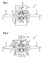
- an only partially illustrated piston engine 1 which can be arranged in particular in a motor vehicle, comprises a plurality of cylinders 3 in an engine block 2, of which, however, only one is shown here.
- Each cylinder 3 encloses a combustion chamber 4, in which the actual combustion process takes place.
- a piston not shown, mounted in a stroke-adjustable manner, which varies the combustion chamber volume in a known manner by its stroke.
- the combustion chambers 4 are connected to a fresh gas system 5 of the piston engine 1, which supplies the individual combustion chambers 4 according to an arrow 6 fresh gas during operation of the piston engine 1.
- an exhaust system 7 of the piston engine 1 is connected to the combustion chambers 4, which dissipates combustion exhaust gases according to an arrow 8 during operation of the piston engine 1.
- the fresh gas system 5 has two separate gas paths, namely a full load path 9 and a partial load path 10.
- the fresh gas 6 is via these two gas paths 9, 10 to the respective combustion chamber 4 fed.
- the full-load path 9 is provided with a larger flow-through cross-section than the partial load path 10. In principle, however, an embodiment with flow cross-sections of equal size is also possible.
- the piston engine 1 is equipped with an inlet-side valve arrangement 11 and with an outlet-side valve arrangement 12 for controlling the charge exchange in the respective cylinders 3. While the inlet-side valve arrangement 11 controls the fresh gas flow guided through the gas paths 9, 10 into the respective combustion chamber 4, the outlet-side valve arrangement 12 controls the exhaust gas flow led out of the respective combustion chamber 4. Furthermore, a control device 13 is provided, which is e.g. a control unit 23, with which at least the inlet-side valve arrangement 11 can be actuated.
- This control device 13 or the control unit 23 is designed so that at partial load of the piston engine 1, the inlet-side valve assembly 11 is driven so that the Vollastpfad 9 is permanently locked, while the inlet-side valve assembly 11 with respect to the partial load path 10 is controlled so that the partial load path 10 is operated or operated to control the required fresh gas flow.
- the control device 13 or the control device 23 for the full-load operation of the piston engine 1 is designed such that at least the full load path 9 for controlling the fresh gas flow is actuated by appropriate activation of the inlet-side valve arrangement 11, in particular such that the full load path 9 at least during one Inlet stroke of each piston is permanently open maximum.
- control device 13 can actuate the partial load path 10 for controlling a fresh gas substream via the control unit 23 during full-load operation, in particular such that the partial load path 10 is also fully open at full load at least during an intake stroke of the respective piston. In principle, however, the partial load path 10 may be locked at full load.
- the inlet-side valve arrangement 11 has a part-load inlet valve 14 assigned exclusively to the partial load path 10, as well as a full-load inlet valve 15 assigned exclusively to the full-load path 9.
- the outlet-side valve arrangement 12 also has two outlet valves 16, which are preferably always actuated synchronously.
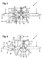
- FIG. 4 shows an embodiment in which the valve assemblies 11, 12 each have only one valve on the inlet side and outlet side, namely an inlet valve 17 and an outlet valve 18.
- the two intake valves 14, 15 can be actuated independently of one another and arbitrarily or can be actuated for opening and closing.
- the exhaust valves 16 are here exemplarily actuated arbitrarily.
- Corresponding actuators are designated 19 and connected in a suitable manner to the control unit 23.
- the actuators 19 are electromagnetic actuators.
- the control unit 23 is now designed such that it permanently blocks the full load intake valve 15 at partial load, while it actuates the partial load intake valve 14 for controlling the required fresh gas flow.
- the respective fresh gas flow can be controlled by selecting the opening time and the closing time for the partial load intake valve 14.
- the amount of fresh gas supplied can be adjusted by varying the opening stroke of the partial load intake valve 14.
- the control device 13 is designed such that it controls the required Frischgasstrom via the control unit 23 by corresponding actuation of the full load intake valve 15.
- the control of the fresh gas flow is preferably substantially reduced to the fact that the full-load intake valve 15 is permanently open during the intake stroke of the piston maximum maximum available fresh gas quantity to be supplied.
- the partial-load intake valve 14, in particular during the intake stroke can also be permanently open and maximum.
- this is not absolutely necessary.
- Figs. 2 to 4 show embodiments in which the exhaust valves 16 are positively controlled, e.g. can be actuated by means of camshafts 20. With camshafts 20 driven exhaust valves 16, 18 can be realized significantly cheaper.
- the partial load path 10 upstream of the partial load intake valve 14 includes a part-load additional valve 21 which is adjustable at least between an open position and a closed position.
- the partial load additional valve 21 is coupled to a corresponding actuator 22 which is connected to the control unit 23.
- the actuator 22 may be, for example, a high-speed adjusting device, which allows, for example, the part-load additional valve 21 in less than 5ms between two end positions switch.
- the partial load additional valve 21 is operated arbitrarily.
- the partial load intake valve 14 is positively controlled, for example by means of a camshaft 20.
- Such a valvetrain is compared to the electromagnetic actuator 19 of FIG. 1 considerably cheaper realized.
- the full-load intake valve 15 can still be actuated arbitrarily, in particular by means of an electromagnetic actuator 19.
- the part-load additional valve 21 can be constructed comparatively inexpensive, since it must preferably be adjustable only between a blocking position and an open position. Intermediate positions or throttle positions are not required.
- the control device 13 is designed such that it opens the partial load intake valve 14 at partial load at the beginning of an intake stroke of the piston assigned to the respective cylinder 3 and closes or blocks it at the end of this intake stroke. This is achieved by means of the camshaft 20, ie by means of a positive control which is coupled to the piston movement.
- the control device 13 actuates the actuator 19 of the full load intake valve 15 for permanently blocking the full load path 9.
- the fresh gas flow can then be controlled by the control device 13 via the control device 23 by corresponding actuations of the actuator 22, ie by actuation of the partial load additional valve 21 will be realized.
- By specifically adjustable opening times and closing times of the partial load additional valve 21 can be realized desired dynamic effects, in particular by multi-phase loading operations.
- the control device 13 actuates the full load intake valve 15 via its control unit 23 for opening the full load path 9 during the respective intake stroke.
- an additional valve namely a full-load additional valve 24 is disposed in the full load path 9 upstream of the full load intake valve 15, which is actuated via a corresponding actuator 25.
- the full-load intake valve 15 can then be inexpensively operated by a positive control, e.g. also by means of a camshaft 20.
- the camshafts 20 and the actuators 19, 22, 25 thereby form components of the control device 13, as well as the control unit 23 connected to the actuators 19, 22, 25.
- the control device 13 is designed so that it opens the two intake valves 14, 15 at partial load and full load via the respective positive control (eg the camshaft 20) at the beginning of the intake stroke of the associated piston and the end of the intake stroke locks.
- the full-load additional valve 24 is permanently controlled by the control unit 23 to block. The adjustment of the fresh gas flow then takes place via corresponding actuations of the partial load additional valve 21.
- the control unit 23 actuates the full-load additional valve 24 for opening, in which case it may in particular be permanently open and maximum.
- the part-load additional valve 21 in particular permanently and completely, be open.
- FIG. 4 differs from the embodiment shown in FIG. 3 only in that a common inlet valve 17 is associated with the gas paths 9, 10.
- the actuation of the additional valves 21, 24 takes place for part load and full load analogous to the embodiment shown in Fig. 3.
- the fresh gas system 5 is preferably configured throttle-free. That is, the fresh gas system 5 upstream of the intake valves 14, 15, 17 and upstream of the additional valves 21, 24 contains no throttle device for throttling the fresh gas flow. In other words, the fresh gas system 5 is designed Entschrosselt.
- the control of the fresh gas flow in the embodiments of FIGS. 2 to 4 preferably takes place in that the part-load additional valve 21 is adjusted exclusively between its blocking position and its open position.
- the partial load additional valve 21 is suitably permanently open, so that a part of the respective combustion chamber 4 supplied fresh gas 6 passes through the partial load path 10 into the respective combustion chamber 4.
- the full-load additional valve 24 and in particular also the partial load additional valve 21 may be permanently open, so that the fresh gas flow exclusively by the opening and locking of the inlet valve 17 and the inlet valves 14, 15th is controlled.
- the full-load additional valve 24 may in principle be designed comparatively slowly, in particular the switching times of the full-load additional valve 24 may be greater than the switching times of the intake valves 14, 15, 17. In contrast, the switching times of the partial load Additional valve 21 may be smaller than the switching times of the intake valves 14, 15, 17.
- the control device 13 via its control unit 23 and the associated actuator 22, the part-load additional valve 21 in part-load operation so that during the intake 3 temporally spaced Einströmphasen or loading phases for the respective combustion chamber 4 can be realized.
- Conceivable for example, an initial loading phase, which includes the opening of the respective inlet valve 14, 15, 17, a final loading phase, which includes the closing of the respective inlet valve 14.1, 17, and a middle Loading phase, which lies between the other two loading phases.
- the full-load additional valve 24 may be equipped with a high-speed actuator as the actuator 25 in order to realize extremely short switching times.
- the control device 13 can control the full-load additional valve 24 for realizing a pulse charging of the respective combustion chamber 4 via its control unit 23 at full load.
Landscapes
- Engineering & Computer Science (AREA)
- Chemical & Material Sciences (AREA)
- Combustion & Propulsion (AREA)
- Mechanical Engineering (AREA)
- General Engineering & Computer Science (AREA)
- Output Control And Ontrol Of Special Type Engine (AREA)
Applications Claiming Priority (1)
| Application Number | Priority Date | Filing Date | Title |
|---|---|---|---|
| DE102006020258A DE102006020258A1 (de) | 2006-04-27 | 2006-04-27 | Kolbenmotor |
Publications (3)
| Publication Number | Publication Date |
|---|---|
| EP1849976A2 true EP1849976A2 (fr) | 2007-10-31 |
| EP1849976A3 EP1849976A3 (fr) | 2010-01-20 |
| EP1849976B1 EP1849976B1 (fr) | 2011-07-27 |
Family
ID=38328575
Family Applications (1)
| Application Number | Title | Priority Date | Filing Date |
|---|---|---|---|
| EP07106467A Not-in-force EP1849976B1 (fr) | 2006-04-27 | 2007-04-19 | Moteur à pistons |
Country Status (3)
| Country | Link |
|---|---|
| US (1) | US7789064B2 (fr) |
| EP (1) | EP1849976B1 (fr) |
| DE (1) | DE102006020258A1 (fr) |
Families Citing this family (4)
| Publication number | Priority date | Publication date | Assignee | Title |
|---|---|---|---|---|
| DE102008046596A1 (de) * | 2008-07-18 | 2010-01-21 | Mahle International Gmbh | Frischluftanlage |
| US8347843B1 (en) | 2011-03-25 | 2013-01-08 | Batiz-Vergara Jose A | Piston for internal combustion engine |
| DE102016201503B4 (de) * | 2016-02-01 | 2019-01-17 | Bayerische Motoren Werke Aktiengesellschaft | Drosselklappe geteilt für Drall |
| KR20180135141A (ko) * | 2017-06-09 | 2018-12-20 | 현대자동차주식회사 | 차량의 흡기조절장치 |
Family Cites Families (7)
| Publication number | Priority date | Publication date | Assignee | Title |
|---|---|---|---|---|
| DE3044292C2 (de) * | 1980-11-25 | 1985-06-20 | Adam Opel AG, 6090 Rüsselsheim | Steuerung eines mehrzylindrigen, fremdgezündeten Einspritz-Verbrennungsmotor |
| US4488531A (en) * | 1981-04-06 | 1984-12-18 | Mazda Motor Corporation | Plural intake system for supercharged engine |
| JPS60224933A (ja) | 1984-04-24 | 1985-11-09 | Nissan Motor Co Ltd | 内燃機関の吸気装置 |
| DE3434476A1 (de) * | 1984-09-20 | 1986-02-27 | Bayerische Motoren Werke AG, 8000 München | Gemischverdichtende, fremdgezuendete hubkolben-brennkraftmaschine |
| JPS62291434A (ja) * | 1986-06-09 | 1987-12-18 | Nissan Motor Co Ltd | 内燃機関の吸気装置 |
| JP2003003855A (ja) * | 2001-06-19 | 2003-01-08 | Denso Corp | 内燃機関の吸気装置 |
| JP4045844B2 (ja) * | 2002-04-19 | 2008-02-13 | 日産自動車株式会社 | エンジンの制御装置 |
-
2006
- 2006-04-27 DE DE102006020258A patent/DE102006020258A1/de not_active Withdrawn
-
2007
- 2007-04-19 EP EP07106467A patent/EP1849976B1/fr not_active Not-in-force
- 2007-04-26 US US11/796,071 patent/US7789064B2/en not_active Expired - Fee Related
Also Published As
| Publication number | Publication date |
|---|---|
| DE102006020258A1 (de) | 2007-11-15 |
| US7789064B2 (en) | 2010-09-07 |
| EP1849976A3 (fr) | 2010-01-20 |
| EP1849976B1 (fr) | 2011-07-27 |
| US20070251495A1 (en) | 2007-11-01 |
Similar Documents
| Publication | Publication Date | Title |
|---|---|---|
| EP1001143A2 (fr) | Commande de soupape pour soupapes d'admission et d'échappement de moteur à combustion interne | |
| EP2049779B1 (fr) | Moteur à combustion | |
| EP2412954A1 (fr) | Procédé de freinage moteur | |
| DE102004008350A1 (de) | Motorventilbetätigungssystem | |
| DE19754287A1 (de) | Brennkraftmaschine | |
| EP1849976B1 (fr) | Moteur à pistons | |
| DE102007042053A1 (de) | Kolbenmotor | |
| DE10155669A1 (de) | Vorrichtung zur Steuerung mindestens eines Gaswechselventils | |
| EP1760278A2 (fr) | Système de contrôle de course variable de soupape pour un moteur à combustion | |
| DE19837693A1 (de) | Anordnung zur Steuerung einer Vorrichtung zum Verändern der Steuerzeiten von Gaswechselventilen einer Brennkraftmaschine | |
| EP1849979B1 (fr) | Moteur à piston et procédé de fonctionnement correspondant | |
| DE102008036494A1 (de) | Brennkraftmaschine und zugehöriges Betriebsverfahren | |
| DE10359935A1 (de) | Motorventilbetätigungssystem | |
| EP1840352B1 (fr) | Système d'alimentation d'air frais et méthode d'opération pour un moteur à piston | |
| DE4341945A1 (de) | Hybridgesteuerter Viertakt-Ottomotor | |
| DE19611362C1 (de) | Zylinderkopf einer Brennkraftmaschine | |
| DE102005048951B4 (de) | Dieselmotor mit Vierventil-Zylinderkopf und Verfahren zur Drallsteuerung | |
| DE69917274T2 (de) | Brennkraftmaschine | |
| EP0325162B1 (fr) | Procédé de commande de la puissance pour un moteur à combustion interne à pistons contrôlé par le remplissage des cylindres | |
| DE19855932A1 (de) | Vorrichtung zur Steuerung von Gaswechselventilen an einer Brennkraftmaschine | |
| DE102004050225A1 (de) | Verfahren zum Betreiben einer Brennkraftmaschine | |
| DE102015205297A1 (de) | Brennkraftmaschine | |
| EP1375843B1 (fr) | Moteur à combustion interne | |
| EP3502435B1 (fr) | Moteur à combustion interne à quatre cylindres et procédé de fonctionnement d'un tel moteur à combustion interne | |
| WO2009062586A1 (fr) | Dispositif de commande de soupapes |
Legal Events
| Date | Code | Title | Description |
|---|---|---|---|
| PUAI | Public reference made under article 153(3) epc to a published international application that has entered the european phase |
Free format text: ORIGINAL CODE: 0009012 |
|
| AK | Designated contracting states |
Kind code of ref document: A2 Designated state(s): AT BE BG CH CY CZ DE DK EE ES FI FR GB GR HU IE IS IT LI LT LU LV MC MT NL PL PT RO SE SI SK TR |
|
| AX | Request for extension of the european patent |
Extension state: AL BA HR MK YU |
|
| PUAL | Search report despatched |
Free format text: ORIGINAL CODE: 0009013 |
|
| AK | Designated contracting states |
Kind code of ref document: A3 Designated state(s): AT BE BG CH CY CZ DE DK EE ES FI FR GB GR HU IE IS IT LI LT LU LV MC MT NL PL PT RO SE SI SK TR |
|
| AX | Request for extension of the european patent |
Extension state: AL BA HR MK RS |
|
| 17P | Request for examination filed |
Effective date: 20100715 |
|
| AKX | Designation fees paid |
Designated state(s): DE FR GB |
|
| GRAP | Despatch of communication of intention to grant a patent |
Free format text: ORIGINAL CODE: EPIDOSNIGR1 |
|
| GRAS | Grant fee paid |
Free format text: ORIGINAL CODE: EPIDOSNIGR3 |
|
| GRAA | (expected) grant |
Free format text: ORIGINAL CODE: 0009210 |
|
| AK | Designated contracting states |
Kind code of ref document: B1 Designated state(s): DE FR GB |
|
| REG | Reference to a national code |
Ref country code: GB Ref legal event code: FG4D Free format text: NOT ENGLISH |
|
| REG | Reference to a national code |
Ref country code: DE Ref legal event code: R096 Ref document number: 502007007775 Country of ref document: DE Effective date: 20110922 |
|
| PLBE | No opposition filed within time limit |
Free format text: ORIGINAL CODE: 0009261 |
|
| STAA | Information on the status of an ep patent application or granted ep patent |
Free format text: STATUS: NO OPPOSITION FILED WITHIN TIME LIMIT |
|
| 26N | No opposition filed |
Effective date: 20120502 |
|
| REG | Reference to a national code |
Ref country code: DE Ref legal event code: R097 Ref document number: 502007007775 Country of ref document: DE Effective date: 20120502 |
|
| PGFP | Annual fee paid to national office [announced via postgrant information from national office to epo] |
Ref country code: GB Payment date: 20140430 Year of fee payment: 8 |
|
| PGFP | Annual fee paid to national office [announced via postgrant information from national office to epo] |
Ref country code: FR Payment date: 20140428 Year of fee payment: 8 Ref country code: DE Payment date: 20140627 Year of fee payment: 8 |
|
| REG | Reference to a national code |
Ref country code: DE Ref legal event code: R119 Ref document number: 502007007775 Country of ref document: DE |
|
| GBPC | Gb: european patent ceased through non-payment of renewal fee |
Effective date: 20150419 |
|
| PG25 | Lapsed in a contracting state [announced via postgrant information from national office to epo] |
Ref country code: DE Free format text: LAPSE BECAUSE OF NON-PAYMENT OF DUE FEES Effective date: 20151103 Ref country code: GB Free format text: LAPSE BECAUSE OF NON-PAYMENT OF DUE FEES Effective date: 20150419 |
|
| REG | Reference to a national code |
Ref country code: FR Ref legal event code: ST Effective date: 20151231 |
|
| PG25 | Lapsed in a contracting state [announced via postgrant information from national office to epo] |
Ref country code: FR Free format text: LAPSE BECAUSE OF NON-PAYMENT OF DUE FEES Effective date: 20150430 |