EP1849979A2 - Moteur à piston et correspondant procédé de fonctionnement - Google Patents
Moteur à piston et correspondant procédé de fonctionnement Download PDFInfo
- Publication number
- EP1849979A2 EP1849979A2 EP07106469A EP07106469A EP1849979A2 EP 1849979 A2 EP1849979 A2 EP 1849979A2 EP 07106469 A EP07106469 A EP 07106469A EP 07106469 A EP07106469 A EP 07106469A EP 1849979 A2 EP1849979 A2 EP 1849979A2
- Authority
- EP
- European Patent Office
- Prior art keywords
- fresh gas
- fuel
- piston engine
- cylinder
- additional valve
- Prior art date
- Legal status (The legal status is an assumption and is not a legal conclusion. Google has not performed a legal analysis and makes no representation as to the accuracy of the status listed.)
- Granted
Links
- 238000000034 method Methods 0.000 title claims description 12
- 239000000446 fuel Substances 0.000 claims abstract description 52
- 238000002485 combustion reaction Methods 0.000 claims abstract description 40
- 238000005259 measurement Methods 0.000 claims description 3
- 239000007789 gas Substances 0.000 claims 30
- 238000007599 discharging Methods 0.000 claims 2
- 239000002737 fuel gas Substances 0.000 claims 1
- 239000000523 sample Substances 0.000 claims 1
- 238000011144 upstream manufacturing Methods 0.000 description 8
- 230000001419 dependent effect Effects 0.000 description 4
- 230000000694 effects Effects 0.000 description 3
- 230000006978 adaptation Effects 0.000 description 2
- 239000003344 environmental pollutant Substances 0.000 description 2
- 231100000719 pollutant Toxicity 0.000 description 2
- 230000004913 activation Effects 0.000 description 1
- 239000003054 catalyst Substances 0.000 description 1
- 238000006243 chemical reaction Methods 0.000 description 1
- 230000006835 compression Effects 0.000 description 1
- 238000007906 compression Methods 0.000 description 1
- 238000010586 diagram Methods 0.000 description 1
- 238000002955 isolation Methods 0.000 description 1
- 238000011017 operating method Methods 0.000 description 1
- 230000002028 premature Effects 0.000 description 1
Images
Classifications
-
- F—MECHANICAL ENGINEERING; LIGHTING; HEATING; WEAPONS; BLASTING
- F02—COMBUSTION ENGINES; HOT-GAS OR COMBUSTION-PRODUCT ENGINE PLANTS
- F02D—CONTROLLING COMBUSTION ENGINES
- F02D41/00—Electrical control of supply of combustible mixture or its constituents
- F02D41/0002—Controlling intake air
-
- F—MECHANICAL ENGINEERING; LIGHTING; HEATING; WEAPONS; BLASTING
- F02—COMBUSTION ENGINES; HOT-GAS OR COMBUSTION-PRODUCT ENGINE PLANTS
- F02B—INTERNAL-COMBUSTION PISTON ENGINES; COMBUSTION ENGINES IN GENERAL
- F02B29/00—Engines characterised by provision for charging or scavenging not provided for in groups F02B25/00, F02B27/00 or F02B33/00 - F02B39/00; Details thereof
- F02B29/08—Modifying distribution valve timing for charging purposes
- F02B29/083—Cyclically operated valves disposed upstream of the cylinder intake valve, controlled by external means
-
- F—MECHANICAL ENGINEERING; LIGHTING; HEATING; WEAPONS; BLASTING
- F02—COMBUSTION ENGINES; HOT-GAS OR COMBUSTION-PRODUCT ENGINE PLANTS
- F02D—CONTROLLING COMBUSTION ENGINES
- F02D13/00—Controlling the engine output power by varying inlet or exhaust valve operating characteristics, e.g. timing
- F02D13/02—Controlling the engine output power by varying inlet or exhaust valve operating characteristics, e.g. timing during engine operation
- F02D13/0276—Actuation of an additional valve for a special application, e.g. for decompression, exhaust gas recirculation or cylinder scavenging
-
- F—MECHANICAL ENGINEERING; LIGHTING; HEATING; WEAPONS; BLASTING
- F02—COMBUSTION ENGINES; HOT-GAS OR COMBUSTION-PRODUCT ENGINE PLANTS
- F02D—CONTROLLING COMBUSTION ENGINES
- F02D41/00—Electrical control of supply of combustible mixture or its constituents
- F02D41/008—Controlling each cylinder individually
-
- F—MECHANICAL ENGINEERING; LIGHTING; HEATING; WEAPONS; BLASTING
- F02—COMBUSTION ENGINES; HOT-GAS OR COMBUSTION-PRODUCT ENGINE PLANTS
- F02D—CONTROLLING COMBUSTION ENGINES
- F02D41/00—Electrical control of supply of combustible mixture or its constituents
- F02D41/02—Circuit arrangements for generating control signals
- F02D41/14—Introducing closed-loop corrections
- F02D41/1438—Introducing closed-loop corrections using means for determining characteristics of the combustion gases; Sensors therefor
- F02D41/1444—Introducing closed-loop corrections using means for determining characteristics of the combustion gases; Sensors therefor characterised by the characteristics of the combustion gases
- F02D41/1454—Introducing closed-loop corrections using means for determining characteristics of the combustion gases; Sensors therefor characterised by the characteristics of the combustion gases the characteristics being an oxygen content or concentration or the air-fuel ratio
-
- Y—GENERAL TAGGING OF NEW TECHNOLOGICAL DEVELOPMENTS; GENERAL TAGGING OF CROSS-SECTIONAL TECHNOLOGIES SPANNING OVER SEVERAL SECTIONS OF THE IPC; TECHNICAL SUBJECTS COVERED BY FORMER USPC CROSS-REFERENCE ART COLLECTIONS [XRACs] AND DIGESTS
- Y02—TECHNOLOGIES OR APPLICATIONS FOR MITIGATION OR ADAPTATION AGAINST CLIMATE CHANGE
- Y02T—CLIMATE CHANGE MITIGATION TECHNOLOGIES RELATED TO TRANSPORTATION
- Y02T10/00—Road transport of goods or passengers
- Y02T10/10—Internal combustion engine [ICE] based vehicles
- Y02T10/12—Improving ICE efficiencies
-
- Y—GENERAL TAGGING OF NEW TECHNOLOGICAL DEVELOPMENTS; GENERAL TAGGING OF CROSS-SECTIONAL TECHNOLOGIES SPANNING OVER SEVERAL SECTIONS OF THE IPC; TECHNICAL SUBJECTS COVERED BY FORMER USPC CROSS-REFERENCE ART COLLECTIONS [XRACs] AND DIGESTS
- Y02—TECHNOLOGIES OR APPLICATIONS FOR MITIGATION OR ADAPTATION AGAINST CLIMATE CHANGE
- Y02T—CLIMATE CHANGE MITIGATION TECHNOLOGIES RELATED TO TRANSPORTATION
- Y02T10/00—Road transport of goods or passengers
- Y02T10/10—Internal combustion engine [ICE] based vehicles
- Y02T10/40—Engine management systems
Definitions
- the present invention relates to a method for operating a piston engine, in particular in a motor vehicle, having the features of the preamble of claim 1.
- the invention also relates to a piston engine, in particular in a motor vehicle, having the features of the preamble of claim 8.
- a piston engine which conventionally has a plurality of cylinders with intake valves, exhaust valves, combustion chambers and pistons adjustable therein. Furthermore, the piston engine comprises a fresh gas system for supplying the combustion chambers with fresh gas, a fuel system for supplying the combustion chambers with fuel and an exhaust system for removing exhaust gas from the combustion chambers.
- the fresh gas system for each cylinder includes an auxiliary valve located upstream of the intake valve of the associated cylinder. With the help of these additional valves, the fresh gas supply of the combustion chambers can be influenced in the known piston engine so that sets a temperature in the respective cylinder, which exceeds the adiabatic compression end temperature goes. This method of operation of the reciprocating engine may also be referred to as a heat load.
- impulse charging For a reciprocating engine, an operating method known as impulse charging is known in which the associated intake valve is briefly closed during an intake stroke of the associated piston during the respective combustion chamber. The dynamic flow effects occurring here lead to the desired impulse charging of the respective combustion chamber.
- the known piston engine operates with an electromagnetic valve control, which allows the intake valves to open arbitrarily and close.
- electromagnetic valve controls are significantly more expensive than conventional camshaft controlled valve trains.
- the properties of the fresh gas system mentioned may change over time, in particular due to wear.
- ⁇ value a predetermined fuel fresh gas ratio
- the momentum introduction into a crankshaft driven by the pistons may vary from cylinder to cylinder if the quantity of fresh gas at the cylinders fluctuates with constant fuel supply.
- An uneven torque distribution along the cylinder leads to a turbulent engine running, which can lead to premature wear of the piston engine.
- the desired ⁇ values can not be met with the corresponding consequences for emissions and fuel consumption.
- the present invention is concerned with the problem of pointing out a possibility for a piston engine of the type mentioned, which improves in particular the engine operation and / or improves the compliance with desired ⁇ values.
- the invention is based on the general idea to control the respective additional valve so that the individual combustion chambers supplied amount of fresh gas cylinder-selectively, so for each cylinder separately and independently of the other cylinders, adjustable or at least influenced.
- a cylinder-selective measurement of the ⁇ -value can be with the help of or the additional valves at set the ⁇ value more or less exactly to a given target value for each cylinder.
- the cylinder-selective Frischgaszuunk means of the respective additional valve within the respective stationary operating state of the piston engine allows the supply of an equal amount of fuel for all cylinders via the fuel system. With the same amount of fuel on all cylinders, upon reaching the target value for the air-fuel ratio, the torque introduction into the crankshaft on all cylinders becomes substantially equal, thereby achieving smooth engine running.
- the present invention is particularly suitable for piston engines, the fresh gas system is entstrosselt or throttle-free configured.
- the additional valve can be used for metering the amount of fresh gas to be supplied to the individual combustion chambers.
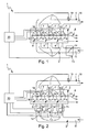
- piston engine 1 and 2 comprises a piston engine 1, which is preferably arranged in a motor vehicle, a fresh gas system 2, an engine block 3, an exhaust system 4 and a fuel system 5. Furthermore, the piston engine 1 in its engine block 3 includes a plurality of cylinders 6, each containing a combustion chamber 7, in each of which a piston 8 is arranged adjustable in stroke and in which a charge change in each case with the aid of at least one inlet valve 9 and at least one exhaust valve 10 is controllable. Corresponding valve trains for driving the gas exchange valves 9, 10 are not indicated here for the sake of clarity.
- the fresh gas system 2 serves to supply the combustion chambers 7 with fresh gas, usually air.
- the fresh gas system 2 has a common fresh gas line 11, from which for each cylinder 6 a single fresh gas pipe 12 goes off.
- Fig. 2 shows an embodiment in which in each fresh gas pipe 12 such an additional valve 13 is arranged.
- the fresh gas system 2 may have two fresh gas lines 11, in each of which such an additional valve 13 is arranged.
- the respective additional valve 13 is adjustable at least between a closed position and an open position.
- a corresponding actuator is designated here by 14 and can be designed as an example as a flap, in particular as a butterfly flap.
- An actuator for driving the respective actuator 14 is not shown here.
- the respective actuator is characterized in that it allows extremely short switching times for the respective switching element 14. In particular, this involves a high-speed actuator which, for example, operates electromagnetically and allows switching times of less than 5 ms, in particular less than 3 ms, for the respective switching element 14.
- the fresh gas system 2 is in each case dethrottled, that is designed throttle-free.
- the fresh gas quantity control is realized here by a corresponding opening and closing of the respective additional valve 13.
- the one cylinder 6 supplied Amount of fresh gas determined during an intake stroke of the respective piston 8 with the inlet valve 9 open by the opening duration of the respective additional valve 13.
- the fresh gas system 2 is at least upstream of the additional valve 13 and upstream of the additional valves 13 throttle-free or de-throttled designed and thus contains upstream of the or the additional valves 13 no special throttle device.
- the fuel system 5 is configured here as an example as a common rail system and accordingly comprises a high-pressure line 15 to which individual injectors 16, each associated with one of the combustion chambers 7, are connected.
- the fuel system 5 serves to supply the combustion chambers 7 with fuel.
- the exhaust system 4 comprises here for each cylinder 6 a separate exhaust pipe 17, via the exhaust gas from the respective associated combustion chamber 7 can be discharged.
- the exhaust pipes 17 lead into a common exhaust pipe 18 of the exhaust system 4 a.
- a ⁇ -sensor 19 is arranged in or on the exhaust pipe 18, ie downstream of the exhaust pipes 17, a ⁇ -sensor 19 is arranged.
- This ⁇ sensor 19 is designed here as a high-speed sensor, such that it can measure ⁇ values, ie fuel fresh-gas ratios ⁇ in the exhaust cylinder-selectively. This means that the exhaust gas quantities sequentially discharged from the individual cylinders 6 can be examined separately with respect to their ⁇ value by the ⁇ sensor 19.
- the controller 20 can assign the ⁇ values determined by the ⁇ sensor 19 to the individual cylinders 6 in order to determine the cylinder-selective ⁇ values. It is clear that instead of a single ⁇ -sensor 19, which is arranged in the exhaust pipe 18, also a plurality of ⁇ -sensors 19 can be used, which are arranged in the individual exhaust pipes 17.
- the controller 20 is used to evaluate the measured values of the ⁇ sensor 19 and to operate the injectors 16, ie the fuel system 5 and to operate the additional valve 13 or the additional valves 13.
- the controller 20 is software and / or hardware configured so that they can operate or control the associated components, in particular the one or more auxiliary valves 13 and the fuel system 5, that with the aid of the controller 20, the method described below for operating the piston engine 1 can be realized.
- ⁇ IST cylinder-selective ⁇ values
- the fuel system 5 is operated in a stationary operating state of the piston engine 1, that is at constant load and speed so that each combustion chamber 7, the same amount of fuel is supplied.
- This amount of fuel is a function of the respective operating state or load state of the piston engine 1 and is optimized in terms of engine efficiency and pollutant emission.
- the corresponding amounts of fuel are stored, for example, in the controller 20.
- a target value ⁇ setpoint for the fuel fresh gas ratio ⁇ is stored, which optimizes its compliance with the piston engine 1 in terms of fuel consumption and pollutant emission.
- the respective additional valve 13 is now operated or controlled so that in said stationary operating state, the individual combustion chambers 7 supplied amount of fresh gas as a function of the measured fuel fresh gas ratio ⁇ Is cylinder-selectively adjusted so that the aforementioned target value A SOLL for the Fuel fresh gas ratio ⁇ can achieve.
- the fuel fresh-gas ratio ⁇ of a combustion process which has taken place in the respective cylinder 6 at an earlier point in time is thus used to determine the next combustion in this cylinder 6 with respect to the target value ⁇ setpoint for the fuel fresh gas.
- the activation of the respective additional valve 13 takes place as a function of the ⁇ value produced in the respective cylinder 6 in the immediately preceding combustion process.
- the full conversion rate of a three-way catalyst is achieved.
- a closed loop can be formed.
- the separately measured for the respective cylinder 6 fuel fresh gas ratio ⁇ then forms an actual value and is therefore denoted by ⁇ Ist .
- the control target is the setting of the target value ⁇ target for the fuel fresh gas ratio ⁇ .
- Controlled variable is the amount of fresh gas that is supplied to the respective cylinder 6. The amount of fresh gas is adjusted separately by a corresponding actuation of the additional valve 13 or the additional valves 13 for each cylinder 6.
- a predetermined standard fresh gas amount is assigned, which is the same size for all cylinders 6. Only when, due to the cylinder-selective measurement of the ⁇ -value, differences in the fuel fresh-gas ratio ⁇ between the individual cylinders 6 are shown during operation, are these differences corrected by appropriate adaptation of the quantity of fresh gas supplied to the individual cylinders 6.
- the controller 20 thus effects a cylinder-selective adaptation of the standard fresh gas quantity originally identical for all cylinders 6 so as to be able to set the fresh gas quantity actually supplied to the individual cylinders 6 in a cylinder-selective manner.
- the adjustment of the amount of fresh gas is carried out by a corresponding actuation or control of the additional valves or 13.
- operating parameters of the respective additional valve 13 for each cylinder 6 individually, so cylinder-selectively varied or adapted. It is possible to change only one or more operating parameters.
- Cylinder-selectively adjustable operating parameters of the respective additional valve 13 are, for example, without claim to completeness, the opening duration of the respective additional valve 13, the opening time of the respective additional valve 13, the closing time of the respective additional valve 13, the opening cross-section of the respective additional valve 13, ie at a stroke-adjustable actuator 14 of Opening stroke and a rotatable adjustable actuator 14, the opening angle or angle of rotation.
- their relative position to the opening and closing times of the respective inlet valves 9 may also be important.
Landscapes
- Engineering & Computer Science (AREA)
- Chemical & Material Sciences (AREA)
- Combustion & Propulsion (AREA)
- Mechanical Engineering (AREA)
- General Engineering & Computer Science (AREA)
- Output Control And Ontrol Of Special Type Engine (AREA)
Applications Claiming Priority (1)
| Application Number | Priority Date | Filing Date | Title |
|---|---|---|---|
| DE102006020349A DE102006020349A1 (de) | 2006-04-28 | 2006-04-28 | Kolbenmotor und zugehöriges Betriebsverfahren |
Publications (3)
| Publication Number | Publication Date |
|---|---|
| EP1849979A2 true EP1849979A2 (fr) | 2007-10-31 |
| EP1849979A3 EP1849979A3 (fr) | 2008-05-28 |
| EP1849979B1 EP1849979B1 (fr) | 2012-08-01 |
Family
ID=38353614
Family Applications (1)
| Application Number | Title | Priority Date | Filing Date |
|---|---|---|---|
| EP07106469A Not-in-force EP1849979B1 (fr) | 2006-04-28 | 2007-04-19 | Moteur à piston et procédé de fonctionnement correspondant |
Country Status (3)
| Country | Link |
|---|---|
| US (1) | US7387116B2 (fr) |
| EP (1) | EP1849979B1 (fr) |
| DE (1) | DE102006020349A1 (fr) |
Cited By (1)
| Publication number | Priority date | Publication date | Assignee | Title |
|---|---|---|---|---|
| DE102011078930A1 (de) | 2011-07-11 | 2013-01-17 | Robert Bosch Gmbh | Verfahren und Vorrichtung zum Betreiben einer Antriebsvorrichtung sowie Computer-Programm-Produkt |
Families Citing this family (4)
| Publication number | Priority date | Publication date | Assignee | Title |
|---|---|---|---|---|
| DE102010061859A1 (de) * | 2010-11-24 | 2012-05-24 | Mahle International Gmbh | Betriebsverfahren |
| DE102010061858A1 (de) * | 2010-11-24 | 2012-05-24 | Mahle International Gmbh | Betriebsverfahren |
| US20120260897A1 (en) * | 2011-04-13 | 2012-10-18 | GM Global Technology Operations LLC | Internal Combustion Engine |
| US8915081B2 (en) | 2011-04-13 | 2014-12-23 | GM Global Technology Operations LLC | Internal combustion engine |
Citations (3)
| Publication number | Priority date | Publication date | Assignee | Title |
|---|---|---|---|---|
| DE4308931C2 (de) | 1993-03-19 | 1997-02-20 | Schatz Oskar | Vorrichtung zum Aufladen einer Brennkraftmaschine der Kolbenbauart |
| EP1088977A2 (fr) | 1999-09-29 | 2001-04-04 | Volkswagen Aktiengesellschaft | Méthode pour contrôler la quantité d'air aspirée par un moteur à tubulures d'admission multiples |
| EP1188916A2 (fr) | 2000-09-19 | 2002-03-20 | Bayerische Motoren Werke Aktiengesellschaft | Méthode et dispositif de commande de remplissage par cylindre de moteurs à calage de soupapes variables |
Family Cites Families (18)
| Publication number | Priority date | Publication date | Assignee | Title |
|---|---|---|---|---|
| DE3839611A1 (de) * | 1988-11-24 | 1990-05-31 | Pierburg Gmbh | Verfahren zur regelung der abgaszusammensetzung |
| DE4141482A1 (de) * | 1991-12-16 | 1993-06-17 | Schatz Oskar | Verfahren zur luftzufuhr in die brennkammer eines verbrennungsmotors der kolbenbauart in zwei phasen |
| DE4236008C2 (de) * | 1992-10-24 | 2002-03-28 | Bosch Gmbh Robert | Verfahren und Vorrichtung zur adaptiven Einzelzylinder-Lambdaregelung bei einem Motor mit variabler Ventilsteuerung |
| EP0826100B1 (fr) * | 1995-05-03 | 1999-11-03 | Siemens Aktiengesellschaft | Procede de regulation lambda d'un cylindre individuel d'un moteur a combustion interne multi-cylindre |
| DE19731129A1 (de) * | 1997-07-19 | 1999-01-21 | Volkswagen Ag | Einzelzylinderandrosselung unter Einbeziehung der Abgasrückführung |
| DE19859018A1 (de) * | 1998-12-21 | 2000-06-29 | Bosch Gmbh Robert | Verfahren und Vorrichtung zur Zylindergleichstellung bei Brennkraftmaschinen |
| DE19903721C1 (de) * | 1999-01-30 | 2000-07-13 | Daimler Chrysler Ag | Betriebsverfahren für eine Brennkraftmaschine mit Lambdawertregelung und Brennkraftmaschine |
| US6403567B1 (en) | 1999-06-22 | 2002-06-11 | Cv Therapeutics, Inc. | N-pyrazole A2A adenosine receptor agonists |
| JP4065784B2 (ja) * | 2001-04-03 | 2008-03-26 | 株式会社日立製作所 | 内燃機関の制御装置 |
| US6651492B2 (en) * | 2001-11-01 | 2003-11-25 | Ford Global Technologies, Llc | Method and system for controlling partial pressure of air in an intake manifold of an engine |
| DE10206906C1 (de) * | 2002-02-19 | 2003-11-06 | Siemens Ag | Verfahren zur Steuerung einer durch Pienoinjektor eingespritzten Kraftstoffmenge |
| JP4144272B2 (ja) * | 2002-07-10 | 2008-09-03 | トヨタ自動車株式会社 | 内燃機関の燃料噴射量制御装置 |
| US6672060B1 (en) * | 2002-07-30 | 2004-01-06 | Ford Global Technologies, Llc | Coordinated control of electronic throttle and variable geometry turbocharger in boosted stoichiometric spark ignition engines |
| JP2004108183A (ja) * | 2002-09-17 | 2004-04-08 | Denso Corp | 内燃機関の空燃比制御装置 |
| US6805095B2 (en) * | 2002-11-05 | 2004-10-19 | Ford Global Technologies, Llc | System and method for estimating and controlling cylinder air charge in a direct injection internal combustion engine |
| JP4357863B2 (ja) * | 2003-04-14 | 2009-11-04 | 株式会社デンソー | 多気筒内燃機関の気筒別空燃比算出装置 |
| JP4487745B2 (ja) * | 2004-03-25 | 2010-06-23 | 株式会社デンソー | センサ応答特性検出装置 |
| ATE391842T1 (de) * | 2004-06-15 | 2008-04-15 | Fiat Ricerche | Verfahren und einrichtung zur bestimmung der ansaugluftmenge einer brennkraftmaschine basierend auf der messung der sauerstoff- konzentration in einem der brennkraftmaschine zugeführten gasgemisch |
-
2006
- 2006-04-28 DE DE102006020349A patent/DE102006020349A1/de not_active Withdrawn
-
2007
- 2007-04-19 EP EP07106469A patent/EP1849979B1/fr not_active Not-in-force
- 2007-04-20 US US11/788,449 patent/US7387116B2/en not_active Expired - Fee Related
Patent Citations (3)
| Publication number | Priority date | Publication date | Assignee | Title |
|---|---|---|---|---|
| DE4308931C2 (de) | 1993-03-19 | 1997-02-20 | Schatz Oskar | Vorrichtung zum Aufladen einer Brennkraftmaschine der Kolbenbauart |
| EP1088977A2 (fr) | 1999-09-29 | 2001-04-04 | Volkswagen Aktiengesellschaft | Méthode pour contrôler la quantité d'air aspirée par un moteur à tubulures d'admission multiples |
| EP1188916A2 (fr) | 2000-09-19 | 2002-03-20 | Bayerische Motoren Werke Aktiengesellschaft | Méthode et dispositif de commande de remplissage par cylindre de moteurs à calage de soupapes variables |
Non-Patent Citations (1)
| Title |
|---|
| PISCHINGER: "Variable Ventilsteuerung II", EXPERT VERLAG, pages: 244 - 260 |
Cited By (3)
| Publication number | Priority date | Publication date | Assignee | Title |
|---|---|---|---|---|
| DE102011078930A1 (de) | 2011-07-11 | 2013-01-17 | Robert Bosch Gmbh | Verfahren und Vorrichtung zum Betreiben einer Antriebsvorrichtung sowie Computer-Programm-Produkt |
| WO2013007428A1 (fr) | 2011-07-11 | 2013-01-17 | Robert Bosch Gmbh | Procédé et dispositif pour faire fonctionner un moteur à combustion interne |
| US9376976B2 (en) | 2011-07-11 | 2016-06-28 | Robert Bosch Gmbh | Method and device for operating an internal combustion engine |
Also Published As
| Publication number | Publication date |
|---|---|
| EP1849979B1 (fr) | 2012-08-01 |
| US7387116B2 (en) | 2008-06-17 |
| US20070251513A1 (en) | 2007-11-01 |
| DE102006020349A1 (de) | 2007-10-31 |
| EP1849979A3 (fr) | 2008-05-28 |
Similar Documents
| Publication | Publication Date | Title |
|---|---|---|
| EP2267291A2 (fr) | Moteur à piston et méthode d'opération | |
| DE19622891C2 (de) | Abgasrückführungssystem | |
| EP1455078B1 (fr) | Moteur à combustion interne ayant un turbocompresseur et un système de recyclage des gaz d'échappement | |
| WO2008017605A1 (fr) | Moteur à combustion | |
| EP1849979B1 (fr) | Moteur à piston et procédé de fonctionnement correspondant | |
| DE102010061858A1 (de) | Betriebsverfahren | |
| DE102007042053A1 (de) | Kolbenmotor | |
| DE2856595A1 (de) | Kraftstoff-steuerventil fuer mehrzylinder-dieselmotoren | |
| AT3671U1 (de) | Brennkraftmaschine mit innerer verbrennung | |
| EP2427647A1 (fr) | Moteur à combustion interne et procédé de fonctionnement associé | |
| WO2006111280A1 (fr) | Moteur thermique a recyclage des gaz d'echappement | |
| EP1857660B1 (fr) | Méthode de contrôle d'un moteur à combustion | |
| DE10250771B4 (de) | Motorbremseinrichtung und Verfahren zu deren Steuerung | |
| EP1079091B1 (fr) | Système de régulation pour moteur Diesel | |
| DE102017203445B3 (de) | Verfahren und Vorrichtung zur Steuerung eines von einem Abgasturbolader aufgeladenen Verbrennungsmotors | |
| DE102010061859A1 (de) | Betriebsverfahren | |
| DE102015204505A1 (de) | Verfahren zum Betreiben einer fremdgezündeten, direkteinspritzenden Brennkraftmaschine sowie fremdgezündete, direkteinspritzende Brennkraftmaschine | |
| DE102015214930B4 (de) | Verfahren zum Ändern einer Aufteilung auf Saugrohreinspritzung und Direkteinspritzung bei einer Brennkraftmaschine | |
| EP1304464A2 (fr) | Méthode d'utilisation d'un moteur à combustion interne multicylindres | |
| DE102006015589A1 (de) | Frischgasanlage und Betriebsverfahren für einen Kolbenmotor | |
| DE10203032A1 (de) | Kolbenmotor und zugehöriges Betriebsverfahren | |
| DE102014217563B3 (de) | Verfahren und Vorrichtung zur Verbesserung der in den Zylindern einer Brennkraftmaschine erfolgenden Verbrennungsvorgänge mittels einer Nockenwellenverstellung | |
| DE102013100096A1 (de) | Vorrichtung und Verfahren zur Abgasrückführung einer Verbrennungskraftmaschine und eine entsprechende Verbrennungskraftmaschine | |
| EP3492724A1 (fr) | Procédé de commande d'un système de recirculation des gaz d'échappement et moteur à combustion interne doté d'une unité de commande destinée à la mise en oeuvre dudit procédé | |
| DE19835741C2 (de) | Verfahren zum Ansteuern von Stellgliedern einer Brennkraftmaschine |
Legal Events
| Date | Code | Title | Description |
|---|---|---|---|
| PUAI | Public reference made under article 153(3) epc to a published international application that has entered the european phase |
Free format text: ORIGINAL CODE: 0009012 |
|
| AK | Designated contracting states |
Kind code of ref document: A2 Designated state(s): AT BE BG CH CY CZ DE DK EE ES FI FR GB GR HU IE IS IT LI LT LU LV MC MT NL PL PT RO SE SI SK TR |
|
| AX | Request for extension of the european patent |
Extension state: AL BA HR MK YU |
|
| PUAL | Search report despatched |
Free format text: ORIGINAL CODE: 0009013 |
|
| AK | Designated contracting states |
Kind code of ref document: A3 Designated state(s): AT BE BG CH CY CZ DE DK EE ES FI FR GB GR HU IE IS IT LI LT LU LV MC MT NL PL PT RO SE SI SK TR |
|
| AX | Request for extension of the european patent |
Extension state: AL BA HR MK RS |
|
| 17P | Request for examination filed |
Effective date: 20081125 |
|
| AKX | Designation fees paid |
Designated state(s): DE FR GB |
|
| 17Q | First examination report despatched |
Effective date: 20091130 |
|
| GRAP | Despatch of communication of intention to grant a patent |
Free format text: ORIGINAL CODE: EPIDOSNIGR1 |
|
| GRAS | Grant fee paid |
Free format text: ORIGINAL CODE: EPIDOSNIGR3 |
|
| GRAA | (expected) grant |
Free format text: ORIGINAL CODE: 0009210 |
|
| AK | Designated contracting states |
Kind code of ref document: B1 Designated state(s): DE FR GB |
|
| REG | Reference to a national code |
Ref country code: GB Ref legal event code: FG4D Free format text: NOT ENGLISH |
|
| REG | Reference to a national code |
Ref country code: DE Ref legal event code: R096 Ref document number: 502007010294 Country of ref document: DE Effective date: 20121011 |
|
| PLBE | No opposition filed within time limit |
Free format text: ORIGINAL CODE: 0009261 |
|
| STAA | Information on the status of an ep patent application or granted ep patent |
Free format text: STATUS: NO OPPOSITION FILED WITHIN TIME LIMIT |
|
| 26N | No opposition filed |
Effective date: 20130503 |
|
| REG | Reference to a national code |
Ref country code: DE Ref legal event code: R097 Ref document number: 502007010294 Country of ref document: DE Effective date: 20130503 |
|
| PGFP | Annual fee paid to national office [announced via postgrant information from national office to epo] |
Ref country code: GB Payment date: 20140430 Year of fee payment: 8 |
|
| PGFP | Annual fee paid to national office [announced via postgrant information from national office to epo] |
Ref country code: DE Payment date: 20140627 Year of fee payment: 8 Ref country code: FR Payment date: 20140428 Year of fee payment: 8 |
|
| REG | Reference to a national code |
Ref country code: DE Ref legal event code: R119 Ref document number: 502007010294 Country of ref document: DE |
|
| GBPC | Gb: european patent ceased through non-payment of renewal fee |
Effective date: 20150419 |
|
| PG25 | Lapsed in a contracting state [announced via postgrant information from national office to epo] |
Ref country code: DE Free format text: LAPSE BECAUSE OF NON-PAYMENT OF DUE FEES Effective date: 20151103 Ref country code: GB Free format text: LAPSE BECAUSE OF NON-PAYMENT OF DUE FEES Effective date: 20150419 |
|
| REG | Reference to a national code |
Ref country code: FR Ref legal event code: ST Effective date: 20151231 |
|
| PG25 | Lapsed in a contracting state [announced via postgrant information from national office to epo] |
Ref country code: FR Free format text: LAPSE BECAUSE OF NON-PAYMENT OF DUE FEES Effective date: 20150430 |