EP1849996A1 - Elément de montage pour un injecteur - Google Patents
Elément de montage pour un injecteur Download PDFInfo
- Publication number
- EP1849996A1 EP1849996A1 EP06008956A EP06008956A EP1849996A1 EP 1849996 A1 EP1849996 A1 EP 1849996A1 EP 06008956 A EP06008956 A EP 06008956A EP 06008956 A EP06008956 A EP 06008956A EP 1849996 A1 EP1849996 A1 EP 1849996A1
- Authority
- EP
- European Patent Office
- Prior art keywords
- mounting
- injector
- mounting plate
- sleeve
- mounting element
- Prior art date
- Legal status (The legal status is an assumption and is not a legal conclusion. Google has not performed a legal analysis and makes no representation as to the accuracy of the status listed.)
- Withdrawn
Links
- 238000002347 injection Methods 0.000 claims abstract description 6
- 239000007924 injection Substances 0.000 claims abstract description 6
- 239000000446 fuel Substances 0.000 claims abstract description 5
- 238000005476 soldering Methods 0.000 claims description 6
- 238000003466 welding Methods 0.000 claims description 6
- 230000000295 complement effect Effects 0.000 claims description 2
- 239000000463 material Substances 0.000 abstract description 10
- 238000004519 manufacturing process Methods 0.000 abstract description 8
- 238000002485 combustion reaction Methods 0.000 description 4
- 238000000034 method Methods 0.000 description 4
- 238000004026 adhesive bonding Methods 0.000 description 1
- 238000012805 post-processing Methods 0.000 description 1
- 238000012545 processing Methods 0.000 description 1
- 238000009877 rendering Methods 0.000 description 1
- 239000007921 spray Substances 0.000 description 1
Images

Classifications
-
- F—MECHANICAL ENGINEERING; LIGHTING; HEATING; WEAPONS; BLASTING
- F02—COMBUSTION ENGINES; HOT-GAS OR COMBUSTION-PRODUCT ENGINE PLANTS
- F02M—SUPPLYING COMBUSTION ENGINES IN GENERAL WITH COMBUSTIBLE MIXTURES OR CONSTITUENTS THEREOF
- F02M61/00—Fuel-injectors not provided for in groups F02M39/00 - F02M57/00 or F02M67/00
- F02M61/14—Arrangements of injectors with respect to engines; Mounting of injectors
-
- F—MECHANICAL ENGINEERING; LIGHTING; HEATING; WEAPONS; BLASTING
- F02—COMBUSTION ENGINES; HOT-GAS OR COMBUSTION-PRODUCT ENGINE PLANTS
- F02M—SUPPLYING COMBUSTION ENGINES IN GENERAL WITH COMBUSTIBLE MIXTURES OR CONSTITUENTS THEREOF
- F02M61/00—Fuel-injectors not provided for in groups F02M39/00 - F02M57/00 or F02M67/00
- F02M61/16—Details not provided for in, or of interest apart from, the apparatus of groups F02M61/02 - F02M61/14
- F02M61/168—Assembling; Disassembling; Manufacturing; Adjusting
Definitions
- the invention relates to a mounting element for an injector of a fuel injection system as well as an injector with such a mounting element.
- Injectors generally serve to inject finely atomized fuel into the combustion chamber of an internal combustion engine. During the injection process, the injectors generate a spray cone, which must be formed in the combustion chamber in a precisely defined region. For this purpose, it is necessary for the injector to be fixed in a completely specific position. To achieve this, the injector is mounted onto the cylinder head of the internal combustion engine by means of a mounting element.
- a mounting element known from the prior art is displayed in Figure 4.
- the mounting element is manufactured in one piece from a tubular round component.
- the tubular base plate is made of a thick-walled material which is trued on one end of the tubular base plate until it achieves a narrow mounting coil.
- the manufacture is thereby very labor-intensive and time-consuming and is associated with a high material wastage.
- the mounting element according to the invention for an injector of a fuel injection system is characterized by at least one sleeve for partially receiving an injector and a mounting plate for mounting an injector onto a motor vehicle, with the sleeve and the mounting plate being embodied as two individual components.
- the two-part embodiment of the mounting element allows the shell to be manufactured from a thin-walled material. Subsequently, the mounting plate can be easily attached to the sleeve.
- the individual components can thus be manufactured with a very minimal material wastage, which results in low material costs and additionally reduces the processing time for manufacturing the mounting element.
- a particularly advantageous embodiment of the invention is characterized in that the sleeve is configured essentially cylindrical and complementary to a cylindrically configured mounting region of the injector.
- the cylindrical sleeve can be formed from a conventional tube.
- drawn tubes are suitable for this purpose. These feature a high dimensional accuracy so that only a minimal post-processing is required. Drawn tubes are available at low cost in a very wide variety of sizes.
- the mounting plate can in turn be subsequently attached to the cylindrical sleeve of the mounting element in a simple manner.
- a further special embodiment of the invention provides for the mounting plate to be attached to the sleeve by means of welding or soldering.
- the welding or soldering offers a simple, safe and cost-effective option for securely connecting the mounting plate to the sleeve.
- the mounting plate preferably comprises a circular flange, the internal diameter of which corresponds to the external diameter of the cylindrical sleeve, so that the mounting plate can be moved onto the external diameter of the cylindrical sleeve and can be particularly easily mounted.
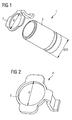
- FIG 1 shows an exemplary embodiment of a claimed two-part mounting element 1 in the unmounted state.
- the mounting element 1 is made of an essentially cylindrically embodied sleeve 3 and a mounting plate 4.
- the mounting plate 4 comprises a circular flange 5.
- the circular flange 5 has an internal diameter d which corresponds to the external diameter D of the cylindrical sleeve 3.
- the mounting plate 4 can be easily moved onto and fixed to the external diameter D of the cylindrical sleeve 3.
- the mounting plate 4 is advantageously mounted to the cylindrical sleeve 3 by means of welding or soldering. Other mounting methods such as gluing or press fitting are however also conceivable.
- the mounting plate 4 can be particularly easily manufactured by means of deep-drawing. During the deep-drawing process, the hole with the internal diameter d can be simultaneously punched out of the mounting plate 4.
- the deep-drawing of the mounting plate 3 enables a particularly cost-effective, simple and rapid manufacture. This hereby allows the mounting plate 4 to be directly formed into its final state in one production step, thereby rendering reworking unnecessary.
- the cylindrical sleeve 3 can be manufactured from a simple conventional tube.
- Drawn tubes are particularly suitable here, since these feature a particularly high surface quality and a high dimensional accuracy.
- the mounting element 1 is configured to consist of two parts, it is no longer necessary to select a sleeve with thick wall thicknesses and then to true these until a narrow mounting coil is achieved. In fact, the tube must still only be minimally reworked. In comparison with the single-part embodiment of the mounting known in the prior art, the manufacture can thus be essentially simplified. The use of two-part components allows a high material wastage to be avoided and considerably reduces the manufacture time.
- the mounting element 1 can be moved over a cylindrical mounting region configured on the injection and can be permanently fixed to the injector. This process is identical to the prior art.
- the injector does not have to be specially adjusted. Older injectors can thus also be reconditioned at any time with the new two-part mounting element 1.
- the mounting element 1 and the injector are preferably connected by means of welding or soldering.
- the injector can be inserted into the cylinder head and can be preferably mounted onto the cylinder head with the mounting plate 4.
- the mounting plate 4 is preferably configured such that the injector can only be inserted in a definite arrangement. This ensures that the injector is always mounted into the cylinder head in the prescribed manner.
- the two-part embodiment of the mounting element 1 provides a particularly simple option for manufacturing the mounting element 1. To this end, a high material wastage can be avoided.
- the two components of the mounting element 1 can be manufactured from standard components in a simple manner.
Landscapes
- Engineering & Computer Science (AREA)
- Chemical & Material Sciences (AREA)
- Combustion & Propulsion (AREA)
- Mechanical Engineering (AREA)
- General Engineering & Computer Science (AREA)
- Manufacturing & Machinery (AREA)
- Fuel-Injection Apparatus (AREA)
Priority Applications (1)
| Application Number | Priority Date | Filing Date | Title |
|---|---|---|---|
| EP06008956A EP1849996A1 (fr) | 2006-04-28 | 2006-04-28 | Elément de montage pour un injecteur |
Applications Claiming Priority (1)
| Application Number | Priority Date | Filing Date | Title |
|---|---|---|---|
| EP06008956A EP1849996A1 (fr) | 2006-04-28 | 2006-04-28 | Elément de montage pour un injecteur |
Publications (1)
| Publication Number | Publication Date |
|---|---|
| EP1849996A1 true EP1849996A1 (fr) | 2007-10-31 |
Family
ID=36942261
Family Applications (1)
| Application Number | Title | Priority Date | Filing Date |
|---|---|---|---|
| EP06008956A Withdrawn EP1849996A1 (fr) | 2006-04-28 | 2006-04-28 | Elément de montage pour un injecteur |
Country Status (1)
| Country | Link |
|---|---|
| EP (1) | EP1849996A1 (fr) |
Citations (3)
| Publication number | Priority date | Publication date | Assignee | Title |
|---|---|---|---|---|
| US4589596A (en) * | 1980-01-03 | 1986-05-20 | Robert Bosch Gmbh | Nozzle for internal combustion engines |
| US6276339B1 (en) * | 2000-05-02 | 2001-08-21 | Delphi Technologies, Inc. | Fuel injector spring clip assembly |
| US20040020469A1 (en) * | 2001-03-16 | 2004-02-05 | Ferdinand Reiter | Fastening device for a fuel injection valve |
-
2006
- 2006-04-28 EP EP06008956A patent/EP1849996A1/fr not_active Withdrawn
Patent Citations (3)
| Publication number | Priority date | Publication date | Assignee | Title |
|---|---|---|---|---|
| US4589596A (en) * | 1980-01-03 | 1986-05-20 | Robert Bosch Gmbh | Nozzle for internal combustion engines |
| US6276339B1 (en) * | 2000-05-02 | 2001-08-21 | Delphi Technologies, Inc. | Fuel injector spring clip assembly |
| US20040020469A1 (en) * | 2001-03-16 | 2004-02-05 | Ferdinand Reiter | Fastening device for a fuel injection valve |
Similar Documents
| Publication | Publication Date | Title |
|---|---|---|
| JP3737130B2 (ja) | 燃料噴射弁及びその製造法 | |
| US4984744A (en) | Electromagnetically actuatable valve | |
| US9970401B2 (en) | Fuel cup | |
| US4477027A (en) | Electromagnetically actuatable valve, in particular a fuel injection valve for fuel injection systems | |
| US20160333836A1 (en) | Fuel injection system having a fuel-conveying component, a fuel injector and connecting device | |
| JP6829869B2 (ja) | オイルジェット装置 | |
| EP3483421B1 (fr) | Rampe d'injection directe d'essence | |
| JP2001165351A (ja) | 接続頭部を有する高圧金属配管およびその頭部成形方法並びに接続頭部用スリーブワッシャ | |
| US20090184184A1 (en) | Fuel Injector and Method for Its Mounting | |
| US8313084B2 (en) | Electromagnetically operatable valve | |
| KR101908831B1 (ko) | 필터 조립체 및 연료 인젝터 | |
| US20090127354A1 (en) | Fuel injection valve | |
| WO2015093163A1 (fr) | Dispositif de distribution/apport en carburant | |
| JP6376859B2 (ja) | オイルジェット装置 | |
| US11092259B2 (en) | Method for producing an electromagnetic valve assembly and electromagnetic valve assembly | |
| US7954223B2 (en) | Method for producing a sealed assembly | |
| CN214092111U (zh) | 一种喷油器及内支撑杆 | |
| CN108240275A (zh) | 燃料喷射阀 | |
| JP2005147075A (ja) | フューエルデリバリパイプ | |
| CN105508108B (zh) | 设有导引元件的阀组件以及流体喷射器 | |
| CN102235282B (zh) | 机动车用燃料分配装置及用于制造燃料分配装置的方法 | |
| JP2012167746A (ja) | ばね組付ユニット及び圧力調整弁用ばね | |
| DE102008040843A1 (de) | Ventil | |
| JP2008063952A (ja) | 電磁式燃料噴射弁 | |
| JPS5824712Y2 (ja) | 内燃機関の高圧燃料噴射管等の管体の接続頭部用スリ−ブワツシヤ |
Legal Events
| Date | Code | Title | Description |
|---|---|---|---|
| PUAI | Public reference made under article 153(3) epc to a published international application that has entered the european phase |
Free format text: ORIGINAL CODE: 0009012 |
|
| AK | Designated contracting states |
Kind code of ref document: A1 Designated state(s): AT BE BG CH CY CZ DE DK EE ES FI FR GB GR HU IE IS IT LI LT LU LV MC NL PL PT RO SE SI SK TR |
|
| AX | Request for extension of the european patent |
Extension state: AL BA HR MK YU |
|
| 17P | Request for examination filed |
Effective date: 20071122 |
|
| 17Q | First examination report despatched |
Effective date: 20080109 |
|
| AKX | Designation fees paid |
Designated state(s): DE FR GB IT |
|
| STAA | Information on the status of an ep patent application or granted ep patent |
Free format text: STATUS: THE APPLICATION IS DEEMED TO BE WITHDRAWN |
|
| 18D | Application deemed to be withdrawn |
Effective date: 20080722 |