EP1850001A2 - Procédé de commande d'une éolienne - Google Patents
Procédé de commande d'une éolienne Download PDFInfo
- Publication number
- EP1850001A2 EP1850001A2 EP07007740A EP07007740A EP1850001A2 EP 1850001 A2 EP1850001 A2 EP 1850001A2 EP 07007740 A EP07007740 A EP 07007740A EP 07007740 A EP07007740 A EP 07007740A EP 1850001 A2 EP1850001 A2 EP 1850001A2
- Authority
- EP
- European Patent Office
- Prior art keywords
- rotor blade
- wind
- rotor
- forces
- component
- Prior art date
- Legal status (The legal status is an assumption and is not a legal conclusion. Google has not performed a legal analysis and makes no representation as to the accuracy of the status listed.)
- Withdrawn
Links
Images

Classifications
-
- F—MECHANICAL ENGINEERING; LIGHTING; HEATING; WEAPONS; BLASTING
- F03—MACHINES OR ENGINES FOR LIQUIDS; WIND, SPRING, OR WEIGHT MOTORS; PRODUCING MECHANICAL POWER OR A REACTIVE PROPULSIVE THRUST, NOT OTHERWISE PROVIDED FOR
- F03D—WIND MOTORS
- F03D7/00—Controlling wind motors
- F03D7/02—Controlling wind motors the wind motors having rotation axis substantially parallel to the air flow entering the rotor
- F03D7/0296—Controlling wind motors the wind motors having rotation axis substantially parallel to the air flow entering the rotor to prevent, counteract or reduce noise emissions
-
- F—MECHANICAL ENGINEERING; LIGHTING; HEATING; WEAPONS; BLASTING
- F03—MACHINES OR ENGINES FOR LIQUIDS; WIND, SPRING, OR WEIGHT MOTORS; PRODUCING MECHANICAL POWER OR A REACTIVE PROPULSIVE THRUST, NOT OTHERWISE PROVIDED FOR
- F03D—WIND MOTORS
- F03D1/00—Wind motors with rotation axis substantially parallel to the air flow entering the rotor
- F03D1/06—Rotors
- F03D1/065—Rotors characterised by their construction elements
- F03D1/0675—Rotors characterised by their construction elements of the blades
-
- F—MECHANICAL ENGINEERING; LIGHTING; HEATING; WEAPONS; BLASTING
- F05—INDEXING SCHEMES RELATING TO ENGINES OR PUMPS IN VARIOUS SUBCLASSES OF CLASSES F01-F04
- F05B—INDEXING SCHEME RELATING TO WIND, SPRING, WEIGHT, INERTIA OR LIKE MOTORS, TO MACHINES OR ENGINES FOR LIQUIDS COVERED BY SUBCLASSES F03B, F03D AND F03G
- F05B2220/00—Application
- F05B2220/70—Application in combination with
- F05B2220/709—Piezoelectric means
-
- F—MECHANICAL ENGINEERING; LIGHTING; HEATING; WEAPONS; BLASTING
- F05—INDEXING SCHEMES RELATING TO ENGINES OR PUMPS IN VARIOUS SUBCLASSES OF CLASSES F01-F04
- F05B—INDEXING SCHEME RELATING TO WIND, SPRING, WEIGHT, INERTIA OR LIKE MOTORS, TO MACHINES OR ENGINES FOR LIQUIDS COVERED BY SUBCLASSES F03B, F03D AND F03G
- F05B2260/00—Function
- F05B2260/96—Preventing, counteracting or reducing vibration or noise
-
- F—MECHANICAL ENGINEERING; LIGHTING; HEATING; WEAPONS; BLASTING
- F05—INDEXING SCHEMES RELATING TO ENGINES OR PUMPS IN VARIOUS SUBCLASSES OF CLASSES F01-F04
- F05B—INDEXING SCHEME RELATING TO WIND, SPRING, WEIGHT, INERTIA OR LIKE MOTORS, TO MACHINES OR ENGINES FOR LIQUIDS COVERED BY SUBCLASSES F03B, F03D AND F03G
- F05B2270/00—Control
- F05B2270/30—Control parameters, e.g. input parameters
- F05B2270/32—Wind speeds
-
- F—MECHANICAL ENGINEERING; LIGHTING; HEATING; WEAPONS; BLASTING
- F05—INDEXING SCHEMES RELATING TO ENGINES OR PUMPS IN VARIOUS SUBCLASSES OF CLASSES F01-F04
- F05B—INDEXING SCHEME RELATING TO WIND, SPRING, WEIGHT, INERTIA OR LIKE MOTORS, TO MACHINES OR ENGINES FOR LIQUIDS COVERED BY SUBCLASSES F03B, F03D AND F03G
- F05B2270/00—Control
- F05B2270/30—Control parameters, e.g. input parameters
- F05B2270/321—Wind directions
-
- F—MECHANICAL ENGINEERING; LIGHTING; HEATING; WEAPONS; BLASTING
- F05—INDEXING SCHEMES RELATING TO ENGINES OR PUMPS IN VARIOUS SUBCLASSES OF CLASSES F01-F04
- F05B—INDEXING SCHEME RELATING TO WIND, SPRING, WEIGHT, INERTIA OR LIKE MOTORS, TO MACHINES OR ENGINES FOR LIQUIDS COVERED BY SUBCLASSES F03B, F03D AND F03G
- F05B2270/00—Control
- F05B2270/30—Control parameters, e.g. input parameters
- F05B2270/322—Control parameters, e.g. input parameters the detection or prediction of a wind gust
-
- F—MECHANICAL ENGINEERING; LIGHTING; HEATING; WEAPONS; BLASTING
- F05—INDEXING SCHEMES RELATING TO ENGINES OR PUMPS IN VARIOUS SUBCLASSES OF CLASSES F01-F04
- F05B—INDEXING SCHEME RELATING TO WIND, SPRING, WEIGHT, INERTIA OR LIKE MOTORS, TO MACHINES OR ENGINES FOR LIQUIDS COVERED BY SUBCLASSES F03B, F03D AND F03G
- F05B2270/00—Control
- F05B2270/40—Type of control system
- F05B2270/404—Type of control system active, predictive, or anticipative
-
- Y—GENERAL TAGGING OF NEW TECHNOLOGICAL DEVELOPMENTS; GENERAL TAGGING OF CROSS-SECTIONAL TECHNOLOGIES SPANNING OVER SEVERAL SECTIONS OF THE IPC; TECHNICAL SUBJECTS COVERED BY FORMER USPC CROSS-REFERENCE ART COLLECTIONS [XRACs] AND DIGESTS
- Y02—TECHNOLOGIES OR APPLICATIONS FOR MITIGATION OR ADAPTATION AGAINST CLIMATE CHANGE
- Y02E—REDUCTION OF GREENHOUSE GAS [GHG] EMISSIONS, RELATED TO ENERGY GENERATION, TRANSMISSION OR DISTRIBUTION
- Y02E10/00—Energy generation through renewable energy sources
- Y02E10/70—Wind energy
- Y02E10/72—Wind turbines with rotation axis in wind direction
Definitions
- the present invention relates to a method for operating a wind turbine, wherein the wind turbine has a plurality of components, but at least a rotor with at least one rotor blade and a generator for converting the mechanical energy of the rotor into electrical energy, wherein one or more characteristics determined, in particular are measured, which are directly or indirectly dependent on the component influencing forces, and / or vice versa depend on the component influencing forces, such as the current wind speed or an operating parameter of the wind turbine, such as the Windanstellwinkel of the rotor blade.
- the present invention further relates to a wind turbine for carrying out the method.
- the rotor blades of a wind turbine are exposed, for example, a high wind load.
- the forces caused by the wind load cause mainly a deformation of the rotor blades.
- the deformation is usually greater at the wing tips than in the rotor blade sections located closer to the rotor center.
- the deformation of the blades influences the respectively set angle of attack of the rotor blades to the wind.
- the actual angle of attack deviates therefore often from the given angle of attack.
- this fixed pre-bend is a compromise. Because only at a certain wind speed, the balance of power are such that the production-side pre-bending compensated exactly by the wind pressure caused deformation. At deviating wind speeds, the position of the rotor blade to the wind is therefore not optimal.
- the object of the present invention is achieved by a method for operating a wind energy plant, which has the features of claim 1 and by a wind energy plant with the features of claim 15.
- one or more characteristic values are determined in the case of a wind power plant which has a plurality of components, but at least one rotor with at least one rotor blade and a generator for converting the mechanical energy of the rotor into electrical energy and possibly a tower on which the rotor is arranged , in particular measured, which are directly or indirectly dependent on the component influencing forces and / or vice versa depend on the component influencing forces, such as the current wind speed or one or more operating parameters of the wind turbine, such as the Windanstellwinkel of the rotor blade.
- opposing forces are introduced into at least one component during the rotational movement of the rotor, which counteract the forces influencing the component, namely at least partially or completely compensate for these forces at least temporarily or completely.
- Controllable force introduction means are understood to mean all technical means by means of which counterforces corresponding to the components can be introduced, the force introduction being controllable. In the simplest case of controllability, the introduction of force can be switched on and off. When using complex force introduction means a variety of parameters of the force introduction can be adjusted, such as the strength of the introduction of force, their duration, their direction, and / or the time or points of introduction of force or the like. The introduction of force can be carried out in particular continuously during the entire rotational movement of the rotor, but also at certain time intervals or at certain times, in particular periodically.
- the deformation forces currently occurring due to wind load can be measured and dependent on suitable sensors of which the parameters of the opposing forces are adjusted.
- the wind speed occurring on the rotor, on the rotor blade and / or in the rotor environment can be measured and, depending on these characteristic values, the parameters of the opposing forces to be introduced can be set.
- the current operating parameters of the wind turbine such as the current Windanstellwinkel the rotor blades, the rotational frequency or rotational speed of the rotor or the like can be determined and adjusted depending on these values, the parameters of the opposing forces to be initiated.
- the opposing forces thereby cause a bias of the rotor blade in the windward direction.
- controllable force introduction means in particular the tensioning device
- tensioning device can be designed in various forms. It is also conceivable, for example, to use a controllable pulling device with ropes, such as wire ropes, about which the rotor blade or other components can be controllably (pre-) tensioned.
- the traction means in particular the tension cords, traction cables, tension chains, tension belts or the like, preferably in the interior of the rotor blade, but outside the rotor blade walls, wherein at least in sections adjacent to the blade connection with respect to the longitudinal extent of the rotor blade , Run first rotor blade third, then passed through the second rotor blade third, and run at least partially in the last, adjacent to the rotor blade tip rotor blade third. It is crucial that the traction means are formed in such a way and can be stretched so that counterforce can be transmitted to the rotor blade via the traction means, which counteract the rotor blade negatively influencing forces.
- the traction means for introducing force are preferably connected to the rotor blade, for example fixed directly to the wall of the rotor blade in the interior of the rotor blade.
- the traction means may be connected in particular with the rotor blade root or the rotor hub, be attached to walls of the rotor blade root or on the rotor hub.
- the tensioner may comprise electroactive polymer strands whose lengths change upon application of an electrical activation voltage. This change in length can be exploited with appropriate arrangement of these strands in / on the component, in particular in / on the rotor blade, to effect suitable deformations of the component, counteract the wind-induced deformations or even completely compensate for them.
- the introduction of force into the or each rotor blade can be controlled periodically such that the bias voltage applied to the rotor blade outside the tower passage is reduced when the rotor blade is pointing downwards in particular in the region of the tower passage , ie the tower area sweeps over. Outside the tower area, the bias of the rotor blade is then increased again to the respective output value. Without this periodic reduction of the prestressing in the tower area, there would be the risk that the prestressing would be greater than necessary due to the low wind load in the tower passage.
- the rotor blade would possibly move without bias reduction during the tower passage from the usual plane of rotation out in the windward direction, which can lead to a load on the rotor blade and aerodynamically unfavorable conditions.
- the counterforces are introduced into the component, in particular the rotor blade, depending on one or more measured in spatial, at least horizontal distance from the rotor on the windward side of the wind turbine parameters that describe the wind conditions in the measuring range , preferably the wind speed and / or the wind direction, wherein the horizontal distance from the rotor, in which the wind parameters are measured, is selected such that the counterforce can be introduced before the wind underlying the wind parameters, in particular a wind front or a wind gust, reached the rotor.
- At least one wind parameter may be measured around the rotor hub with respect to a front view of the windward side of the wind turbine within an imaginary annular region having an inner radius of the annular region greater than half the rotor hub tip to rotor blade tip spacing and having an outer radius that is greater as 3 ⁇ 4 of the distance between the rotor hub and the rotor blade tip, preferably equal to or greater than the entire distance between the rotor hub and the rotor blade tip.
- the wind parameters can generally be measured with location and / or time resolution.
- the initiation of the opposing forces is effected by means of controllably deformable materials.
- controllably deformable materials In addition to the abovementioned electroactive polymers, these may be all materials which can controllably effect dimensional changes.
- At least partially materials - such as electroactive polymers - to integrate directly into the component walls themselves, such as in the rotor blade shells, which are controllably deformable. At least one layer of the component walls may consist at least partially of these materials. The component or the rotor blade can be coated with these deformable materials in particular.
- the component or rotor blade deformation is preferably controlled by means of a controller via which suitable parameters of the force introduction means, such as the tensioning device, are adjusted, such as the activation voltage of the electroactive polymer strands.
- counterforces are induced in the blade connection of one or each rotor blade, which effects a prestressing of the blade end, in particular in the direction of the rotor center. Due to the weight of the respective rotor blade, the often cast-iron blade connection of the rotor blade is exposed to large alternating loads, which can be reduced by the prestressing. Since the effect of the dead weight is greatest when the rotor blade is pointing downwards in the area of the tower passage, i. sweeps over the tower surface, the bias should be at least in the period in which the rotor blade is in this area.
- According to the invention can also be provided to initiate counter forces in the tower of the wind turbine, counteracting, for example, tower vibrations or the like.
- a controllable tensioning device within the tower so that the tower movements are counteracted accordingly by the tensioning device. This can be achieved as with the rotor blades by suitably arranged, electroactive polymer strands.
- counter forces can be introduced into the nacelle connection of a nacelle connected to the tower by means of prestressing of the nacelle connection by means of a tensioning device, which counteract the forces affecting the nacelle connection.
- a tensioning device which counteract the forces affecting the nacelle connection.
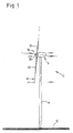
- FIG. 1 shows a wind energy plant 10, which has a gondola 16 arranged on the top of the tower at the upper end of a vertical tower 14 arranged on a horizontal base 12.
- a gondola 16 arranged on the top of the tower at the upper end of a vertical tower 14 arranged on a horizontal base 12.
- various embodiments are conceivable for the exact design of a tower of a wind power plant.
- the invention is not limited to the nature described in the drawing, frusto-conical shape of the tower 14.
- a rotor 18 is arranged, which has a hub 20. Connected to the hub 20 are three rotor blades 22, wherein the rotor blade roots of the rotor blades 22 are inserted into corresponding openings of the hub 20 and connected in a known manner with this.
- the rotor 18 rotates about an axis slightly inclined relative to the horizontal. As soon as wind hits the rotor blades 22, the rotor 18 together with the rotor blades 22 is set in rotation about the rotor axis. The movement of the rotor axis is converted into electrical current by a generator arranged inside the nacelle. The rotor blades 22 sweep a circular area during rotation. About an unillustrated, but known to those skilled in the art, adjusting the rotor blades 22 can be changed individually in their position relative to the wind, that is, the angle of attack of the rotor blades 22 to the wind is adjustable.
- the basic structure of the wind power plant 10 with at least approximately horizontal rotor axis is known in the prior art, so that is dispensed with a detailed illustration of the same.
- the rotor blades 22 are deformed by the wind pressure during the rotational movement of the rotor 18 in the direction of the side facing away from the wind.
- This wind-induced deformation is only partially compensated in the prior art in that the respective rotor blade tip 24 is already slightly bent in the direction of the windward side in terms of production.
- This production-side pre-bend leads to sufficient results only at certain reference speeds. At least at speeds that deviate significantly from this reference speed, however, the respective position of the rotor blade 22 to the wind due to the wind-induced deformation despite pre-bending is insufficient.
- each rotor blade 22 during the operation of the wind energy plant, counter forces are introduced to the forces caused by the wind pressure, which are directed counter to the currently acting, wind-induced forces and at least approximately compensate them, or at least reduce them.
- Each controllable force introduction means of each rotor blade 22 in each case comprises a controllable tensioning device 25 with which the rotor blade 22 can be pretensioned against the wind direction, cf. Fig. 2.
- the tensioning device 25 has at least one strand of electroactive polymers 26 or of materials in which electroactive polymers are at least partially integrated.
- Each electroactive polymer strand 26 is in the region of the rotor blade tip 24, i. in the longitudinal direction of the blade root from last third of the rotor blade attached to the respective rotor blade 22.
- the strand 26 is guided within the rotor blade 22 from this last rotor blade third over the second rotor blade third to the first rotor blade third adjacent to the rotor blade root.
- the other end of the polymer strand 26 is finally attached to the rotor blade tip 24 opposite end of the rotor blade 22 at a suitable position, in particular at the rotor hub 22.
- the activation of the electroactive polymer strand 26 is carried out by applying a suitable electrical voltage and causes the strand 26 is reduced in length.
- the Length reduction of the polymer strand would lead without compensating counter forces to a pivoting of the rotor blade 22 from the position I to position II.
- the electroactive polymer strand 26 and thus the bias of each rotor blade 22 can be controlled by setting suitable parameters.
- the amount of applied electrical voltage for example, the amount of length reduction of the electroactive polymer strand 26, and thus the magnitude of the bias, that counteracts the wind-induced deformation of the rotor blade 22 can be adjusted.
- the amounts and directions of the force components are set in this way, pointing in the windward direction and thus counteract the wind-induced forces.
- Suitable sensors measure the current wind speed. Depending on this characteristic value, the counter force introduction shown above is then controlled. At high wind speeds and thus large wind load each rotor blade 22 is biased accordingly strong in the windward direction. At lower wind speeds, the rotor blades 22 are biased less strong.
- each rotor blade 22 can be controlled so that there is a matched, optimal bias voltage for each wind load or wind speed.
Landscapes
- Engineering & Computer Science (AREA)
- Life Sciences & Earth Sciences (AREA)
- Sustainable Development (AREA)
- Sustainable Energy (AREA)
- Chemical & Material Sciences (AREA)
- Combustion & Propulsion (AREA)
- Mechanical Engineering (AREA)
- General Engineering & Computer Science (AREA)
- Wind Motors (AREA)
Applications Claiming Priority (1)
| Application Number | Priority Date | Filing Date | Title |
|---|---|---|---|
| DE102006020257A DE102006020257A1 (de) | 2006-04-27 | 2006-04-27 | Verfahren zum Betreiben einer Windenergieanlage |
Publications (2)
| Publication Number | Publication Date |
|---|---|
| EP1850001A2 true EP1850001A2 (fr) | 2007-10-31 |
| EP1850001A3 EP1850001A3 (fr) | 2012-12-12 |
Family
ID=38001770
Family Applications (1)
| Application Number | Title | Priority Date | Filing Date |
|---|---|---|---|
| EP07007740A Withdrawn EP1850001A3 (fr) | 2006-04-27 | 2007-04-16 | Procédé de commande d'une éolienne |
Country Status (6)
| Country | Link |
|---|---|
| US (1) | US7878760B2 (fr) |
| EP (1) | EP1850001A3 (fr) |
| CN (1) | CN101092939B (fr) |
| AU (1) | AU2007201849B2 (fr) |
| CA (1) | CA2585954A1 (fr) |
| DE (1) | DE102006020257A1 (fr) |
Cited By (1)
| Publication number | Priority date | Publication date | Assignee | Title |
|---|---|---|---|---|
| EP2362091A1 (fr) * | 2010-06-30 | 2011-08-31 | Envision Energy (Denmark) ApS | Système d'amortissement des vibrations des pales de rotor |
Families Citing this family (8)
| Publication number | Priority date | Publication date | Assignee | Title |
|---|---|---|---|---|
| DE102007020423A1 (de) * | 2007-04-27 | 2008-10-30 | Daubner & Stommel GbR Bau-Werk-Planung (vertretungsberechtigter Gesellschafter: Matthias Stommel, 27777 Ganderkesee) | Verfahren zum Betreiben einer Windenergieanlage und Windenergieanlage |
| WO2009010059A2 (fr) * | 2007-07-14 | 2009-01-22 | Vestas Wind Systems A/S | Commande d'un rotor pendant un processus d'arrêt d'une éolienne |
| US8448527B2 (en) * | 2011-10-14 | 2013-05-28 | General Electric Company | Methods for using site specific wind conditions to determine when to install a tip feature on a wind turbine rotor blade |
| CN103366064B (zh) * | 2013-07-16 | 2016-01-06 | 国家电网公司 | 风电场动态模型参数测试方法 |
| ES2974296T3 (es) * | 2016-06-08 | 2024-06-26 | Gonzalez Perez Adolfo | Unidad eólica sostenible autónoma, rotor reticular multipala, acumulador y convertidor energéticos y aplicaciones |
| CN113847205B (zh) * | 2020-06-28 | 2023-07-18 | 新疆金风科技股份有限公司 | 叶片调整装置、叶轮、风力发电机组及其叶片调整方法 |
| ES3053844T3 (en) | 2020-12-17 | 2026-01-27 | Vestas Wind Sys As | A pitch controlled wind turbine with blade connecting members |
| CN115949549B (zh) * | 2022-12-28 | 2025-08-19 | 明阳智慧能源集团股份公司 | 一种基于发电机转速的风力发电机组前馈控制方法与系统 |
Family Cites Families (22)
| Publication number | Priority date | Publication date | Assignee | Title |
|---|---|---|---|---|
| US3426214A (en) * | 1966-02-07 | 1969-02-04 | Martin J O Malley | Electric power generating system |
| US4464579A (en) * | 1982-06-17 | 1984-08-07 | Control Data Corporation | Derrieus wind turbine electric generating system |
| DE29522190U1 (de) * | 1994-02-07 | 2000-12-14 | Bonus Energy A/S, Brande | Windmühlenblatt |
| US5531567A (en) | 1994-06-20 | 1996-07-02 | Flowind Corporation | Vertical axis wind turbine with blade tensioner |
| DE19712034A1 (de) * | 1997-03-21 | 1998-09-24 | Deutsch Zentr Luft & Raumfahrt | Profilkante eines aerodynamischen Profils |
| DK100497A (da) * | 1997-09-04 | 1997-09-04 | Novo Nordisk As | Kemisk forbindelse |
| DE19804308C2 (de) * | 1997-09-30 | 2003-10-30 | Deutsch Zentr Luft & Raumfahrt | Profil |
| DE19807477C2 (de) * | 1997-09-30 | 2000-01-13 | Deutsch Zentr Luft & Raumfahrt | Rotor |
| ES2244202T3 (es) * | 1998-07-28 | 2005-12-01 | Neg Micon A/S | Pala de turbina eolica con medios de amortiguamiento de oscilaciones en forma de u. |
| DE19856500B4 (de) * | 1998-12-08 | 2005-12-08 | Franz Mitsch | Schwingungstilger |
| DE19860215C1 (de) * | 1998-12-24 | 2000-03-16 | Aerodyn Eng Gmbh | Verfahren zum Betreiben einer Offshore-Windenergieanlage |
| DE10152449A1 (de) * | 2001-10-26 | 2003-05-15 | Aloys Wobben | Rotorblatt für eine Windenergieanlage |
| WO2002073031A1 (fr) * | 2001-03-14 | 2002-09-19 | Benny Klemar | Pale pour eolienne |
| US6465902B1 (en) * | 2001-04-18 | 2002-10-15 | The United States Of America As Represented By The Secretary Of The Navy | Controllable camber windmill blades |
| DE10202995B4 (de) * | 2002-01-26 | 2004-01-29 | Nordex Energy Gmbh | Rotorblatt für eine Windkraftanlage mit einer Dämpfereinrichtung |
| DE10219664A1 (de) * | 2002-04-19 | 2003-11-06 | Enron Wind Gmbh | Windenergieanlage, Regelanordnung für eine Windenergieanlage und Verfahren zum Betreiben einer Windenergieanlage |
| US6769873B2 (en) | 2002-10-08 | 2004-08-03 | The United States Of America As Represented By The Secretary Of The Navy | Dynamically reconfigurable wind turbine blade assembly |
| US6888262B2 (en) * | 2003-02-03 | 2005-05-03 | General Electric Company | Method and apparatus for wind turbine rotor load control |
| GB2398841A (en) * | 2003-02-28 | 2004-09-01 | Qinetiq Ltd | Wind turbine control having a Lidar wind speed measurement apparatus |
| US7086834B2 (en) * | 2004-06-10 | 2006-08-08 | General Electric Company | Methods and apparatus for rotor blade ice detection |
| US7360996B2 (en) * | 2005-12-07 | 2008-04-22 | General Electric Company | Wind blade assembly and method for damping load or strain |
| US7400054B2 (en) * | 2006-01-10 | 2008-07-15 | General Electric Company | Method and assembly for detecting blade status in a wind turbine |
-
2006
- 2006-04-27 DE DE102006020257A patent/DE102006020257A1/de not_active Withdrawn
-
2007
- 2007-04-16 EP EP07007740A patent/EP1850001A3/fr not_active Withdrawn
- 2007-04-23 US US11/738,770 patent/US7878760B2/en not_active Expired - Fee Related
- 2007-04-23 CA CA002585954A patent/CA2585954A1/fr not_active Abandoned
- 2007-04-26 AU AU2007201849A patent/AU2007201849B2/en not_active Ceased
- 2007-04-27 CN CN2007101053542A patent/CN101092939B/zh not_active Expired - Fee Related
Cited By (1)
| Publication number | Priority date | Publication date | Assignee | Title |
|---|---|---|---|---|
| EP2362091A1 (fr) * | 2010-06-30 | 2011-08-31 | Envision Energy (Denmark) ApS | Système d'amortissement des vibrations des pales de rotor |
Also Published As
| Publication number | Publication date |
|---|---|
| CN101092939A (zh) | 2007-12-26 |
| CA2585954A1 (fr) | 2007-10-27 |
| US7878760B2 (en) | 2011-02-01 |
| DE102006020257A1 (de) | 2007-10-31 |
| US20070253818A1 (en) | 2007-11-01 |
| AU2007201849B2 (en) | 2013-01-31 |
| EP1850001A3 (fr) | 2012-12-12 |
| CN101092939B (zh) | 2010-04-14 |
| AU2007201849A1 (en) | 2007-11-15 |
Similar Documents
| Publication | Publication Date | Title |
|---|---|---|
| EP1850001A2 (fr) | Procédé de commande d'une éolienne | |
| DE102005045516A1 (de) | Verfahren zur Anpassung einer Windenergieanlage an gegebene Windverhältnisse | |
| DE10303555B4 (de) | Verfahren zur kranlosen Montage eines Rotorblattes einer Windenergieanlage | |
| EP1785621B1 (fr) | Pale d'éolienne | |
| DE102012206109B3 (de) | Rotorblatt einer Windenergieanlage | |
| DE102007041649A1 (de) | Rotorblatt, Windenergieanlage sowie Verfahren zum Betreiben einer Windenergieanlage | |
| EP1772622A1 (fr) | Procédé de commande d'une éolienne | |
| WO2015090861A1 (fr) | Ensemble comprenant une fondation en béton et une tour et procédé d'érection d'une tour | |
| EP2893187A1 (fr) | Tour éolienne et procédé de stabilisation d'une tour éolienne | |
| EP2914844B1 (fr) | Procédé pour faire fonctionner une éolienne, éolienne et dispositif de commande pour une éolienne | |
| EP1882853A2 (fr) | Eolienne et procédé de fonctionnement d'une éolienne | |
| EP2715117A1 (fr) | Pale courbé du rotor d'une eolienne | |
| WO2017202841A1 (fr) | Dispositif de montée pour la réalisation d'un mouvement par rapport à un mât et procédé de fabrication d'un mât | |
| DE102011122504A1 (de) | Windenergieanlage | |
| WO2020221860A1 (fr) | Rotor pour une éolienne et éolienne | |
| WO2008009352A9 (fr) | Arrangement d'un dispositif de levage sur une pale de rotor d'une installation d'énergie éolienne et procédé correspondant | |
| DE102019113085A1 (de) | Rotorblatt und Windenergieanlage | |
| EP3839249B1 (fr) | Procede de reglage de l'angle de pas d'une pale de rotor, dispositif de commande pour regler l'angle de pas, et eolienne correspondante | |
| EP3990774B1 (fr) | Rotor pour éolienne, éolienne et procédé associé | |
| EP3969741B1 (fr) | Pale de rotor et éolienne | |
| DE102014216685A1 (de) | Verwindbares Rotorblatt | |
| DE102012010834A1 (de) | Verfahren zur Ansteuerung von Rotorblättern | |
| EP2373886A2 (fr) | Position de repos d'une eolienne | |
| DE102008035058A1 (de) | Rotorblatt und Windkraftanlage damit | |
| DE102012102876A1 (de) | Windkraftanlage mit zwei Rotoren |
Legal Events
| Date | Code | Title | Description |
|---|---|---|---|
| PUAI | Public reference made under article 153(3) epc to a published international application that has entered the european phase |
Free format text: ORIGINAL CODE: 0009012 |
|
| AK | Designated contracting states |
Kind code of ref document: A2 Designated state(s): AT BE BG CH CY CZ DE DK EE ES FI FR GB GR HU IE IS IT LI LT LU LV MC MT NL PL PT RO SE SI SK TR |
|
| AX | Request for extension of the european patent |
Extension state: AL BA HR MK YU |
|
| PUAL | Search report despatched |
Free format text: ORIGINAL CODE: 0009013 |
|
| AK | Designated contracting states |
Kind code of ref document: A3 Designated state(s): AT BE BG CH CY CZ DE DK EE ES FI FR GB GR HU IE IS IT LI LT LU LV MC MT NL PL PT RO SE SI SK TR |
|
| AX | Request for extension of the european patent |
Extension state: AL BA HR MK RS |
|
| RIC1 | Information provided on ipc code assigned before grant |
Ipc: F03D 7/02 20060101ALI20121105BHEP Ipc: F03D 1/06 20060101AFI20121105BHEP |
|
| AKY | No designation fees paid | ||
| REG | Reference to a national code |
Ref country code: DE Ref legal event code: R108 |
|
| REG | Reference to a national code |
Ref country code: DE Ref legal event code: R108 Effective date: 20130821 |
|
| STAA | Information on the status of an ep patent application or granted ep patent |
Free format text: STATUS: THE APPLICATION IS DEEMED TO BE WITHDRAWN |
|
| 18D | Application deemed to be withdrawn |
Effective date: 20130613 |