EP1850014A2 - Pompe centrifuge - Google Patents
Pompe centrifuge Download PDFInfo
- Publication number
- EP1850014A2 EP1850014A2 EP07005219A EP07005219A EP1850014A2 EP 1850014 A2 EP1850014 A2 EP 1850014A2 EP 07005219 A EP07005219 A EP 07005219A EP 07005219 A EP07005219 A EP 07005219A EP 1850014 A2 EP1850014 A2 EP 1850014A2
- Authority
- EP
- European Patent Office
- Prior art keywords
- housing part
- centrifugal pump
- pump according
- ring
- housing
- Prior art date
- Legal status (The legal status is an assumption and is not a legal conclusion. Google has not performed a legal analysis and makes no representation as to the accuracy of the status listed.)
- Granted
Links
Images
Classifications
-
- F—MECHANICAL ENGINEERING; LIGHTING; HEATING; WEAPONS; BLASTING
- F04—POSITIVE - DISPLACEMENT MACHINES FOR LIQUIDS; PUMPS FOR LIQUIDS OR ELASTIC FLUIDS
- F04D—NON-POSITIVE-DISPLACEMENT PUMPS
- F04D29/00—Details, component parts, or accessories
- F04D29/02—Selection of particular materials
- F04D29/026—Selection of particular materials especially adapted for liquid pumps
-
- B—PERFORMING OPERATIONS; TRANSPORTING
- B29—WORKING OF PLASTICS; WORKING OF SUBSTANCES IN A PLASTIC STATE IN GENERAL
- B29C—SHAPING OR JOINING OF PLASTICS; SHAPING OF MATERIAL IN A PLASTIC STATE, NOT OTHERWISE PROVIDED FOR; AFTER-TREATMENT OF THE SHAPED PRODUCTS, e.g. REPAIRING
- B29C65/00—Joining or sealing of preformed parts, e.g. welding of plastics materials; Apparatus therefor
- B29C65/02—Joining or sealing of preformed parts, e.g. welding of plastics materials; Apparatus therefor by heating, with or without pressure
- B29C65/14—Joining or sealing of preformed parts, e.g. welding of plastics materials; Apparatus therefor by heating, with or without pressure using wave energy, i.e. electromagnetic radiation, or particle radiation
- B29C65/16—Laser beams
- B29C65/1629—Laser beams characterised by the way of heating the interface
- B29C65/1635—Laser beams characterised by the way of heating the interface at least passing through one of the parts to be joined, i.e. laser transmission welding
-
- B—PERFORMING OPERATIONS; TRANSPORTING
- B29—WORKING OF PLASTICS; WORKING OF SUBSTANCES IN A PLASTIC STATE IN GENERAL
- B29C—SHAPING OR JOINING OF PLASTICS; SHAPING OF MATERIAL IN A PLASTIC STATE, NOT OTHERWISE PROVIDED FOR; AFTER-TREATMENT OF THE SHAPED PRODUCTS, e.g. REPAIRING
- B29C66/00—General aspects of processes or apparatus for joining preformed parts
- B29C66/01—General aspects dealing with the joint area or with the area to be joined
- B29C66/05—Particular design of joint configurations
- B29C66/10—Particular design of joint configurations particular design of the joint cross-sections
- B29C66/12—Joint cross-sections combining only two joint-segments; Tongue and groove joints; Tenon and mortise joints; Stepped joint cross-sections
- B29C66/122—Joint cross-sections combining only two joint-segments, i.e. one of the parts to be joined comprising only two joint-segments in the joint cross-section
- B29C66/1222—Joint cross-sections combining only two joint-segments, i.e. one of the parts to be joined comprising only two joint-segments in the joint cross-section comprising at least a lapped joint-segment
-
- B—PERFORMING OPERATIONS; TRANSPORTING
- B29—WORKING OF PLASTICS; WORKING OF SUBSTANCES IN A PLASTIC STATE IN GENERAL
- B29C—SHAPING OR JOINING OF PLASTICS; SHAPING OF MATERIAL IN A PLASTIC STATE, NOT OTHERWISE PROVIDED FOR; AFTER-TREATMENT OF THE SHAPED PRODUCTS, e.g. REPAIRING
- B29C66/00—General aspects of processes or apparatus for joining preformed parts
- B29C66/01—General aspects dealing with the joint area or with the area to be joined
- B29C66/05—Particular design of joint configurations
- B29C66/10—Particular design of joint configurations particular design of the joint cross-sections
- B29C66/12—Joint cross-sections combining only two joint-segments; Tongue and groove joints; Tenon and mortise joints; Stepped joint cross-sections
- B29C66/122—Joint cross-sections combining only two joint-segments, i.e. one of the parts to be joined comprising only two joint-segments in the joint cross-section
- B29C66/1224—Joint cross-sections combining only two joint-segments, i.e. one of the parts to be joined comprising only two joint-segments in the joint cross-section comprising at least a butt joint-segment
-
- B—PERFORMING OPERATIONS; TRANSPORTING
- B29—WORKING OF PLASTICS; WORKING OF SUBSTANCES IN A PLASTIC STATE IN GENERAL
- B29C—SHAPING OR JOINING OF PLASTICS; SHAPING OF MATERIAL IN A PLASTIC STATE, NOT OTHERWISE PROVIDED FOR; AFTER-TREATMENT OF THE SHAPED PRODUCTS, e.g. REPAIRING
- B29C66/00—General aspects of processes or apparatus for joining preformed parts
- B29C66/01—General aspects dealing with the joint area or with the area to be joined
- B29C66/05—Particular design of joint configurations
- B29C66/10—Particular design of joint configurations particular design of the joint cross-sections
- B29C66/12—Joint cross-sections combining only two joint-segments; Tongue and groove joints; Tenon and mortise joints; Stepped joint cross-sections
- B29C66/124—Tongue and groove joints
-
- B—PERFORMING OPERATIONS; TRANSPORTING
- B29—WORKING OF PLASTICS; WORKING OF SUBSTANCES IN A PLASTIC STATE IN GENERAL
- B29C—SHAPING OR JOINING OF PLASTICS; SHAPING OF MATERIAL IN A PLASTIC STATE, NOT OTHERWISE PROVIDED FOR; AFTER-TREATMENT OF THE SHAPED PRODUCTS, e.g. REPAIRING
- B29C66/00—General aspects of processes or apparatus for joining preformed parts
- B29C66/01—General aspects dealing with the joint area or with the area to be joined
- B29C66/05—Particular design of joint configurations
- B29C66/20—Particular design of joint configurations particular design of the joint lines, e.g. of the weld lines
- B29C66/23—Particular design of joint configurations particular design of the joint lines, e.g. of the weld lines said joint lines being multiple and parallel or being in the form of tessellations
- B29C66/232—Particular design of joint configurations particular design of the joint lines, e.g. of the weld lines said joint lines being multiple and parallel or being in the form of tessellations said joint lines being multiple and parallel, i.e. the joint being formed by several parallel joint lines
-
- B—PERFORMING OPERATIONS; TRANSPORTING
- B29—WORKING OF PLASTICS; WORKING OF SUBSTANCES IN A PLASTIC STATE IN GENERAL
- B29C—SHAPING OR JOINING OF PLASTICS; SHAPING OF MATERIAL IN A PLASTIC STATE, NOT OTHERWISE PROVIDED FOR; AFTER-TREATMENT OF THE SHAPED PRODUCTS, e.g. REPAIRING
- B29C66/00—General aspects of processes or apparatus for joining preformed parts
- B29C66/50—General aspects of joining tubular articles; General aspects of joining long products, i.e. bars or profiled elements; General aspects of joining single elements to tubular articles, hollow articles or bars; General aspects of joining several hollow-preforms to form hollow or tubular articles
- B29C66/51—Joining tubular articles, profiled elements or bars; Joining single elements to tubular articles, hollow articles or bars; Joining several hollow-preforms to form hollow or tubular articles
- B29C66/54—Joining several hollow-preforms, e.g. half-shells, to form hollow articles, e.g. for making balls, containers; Joining several hollow-preforms, e.g. half-cylinders, to form tubular articles
- B29C66/543—Joining several hollow-preforms, e.g. half-shells, to form hollow articles, e.g. for making balls, containers; Joining several hollow-preforms, e.g. half-cylinders, to form tubular articles joining more than two hollow-preforms to form said hollow articles
-
- F—MECHANICAL ENGINEERING; LIGHTING; HEATING; WEAPONS; BLASTING
- F04—POSITIVE - DISPLACEMENT MACHINES FOR LIQUIDS; PUMPS FOR LIQUIDS OR ELASTIC FLUIDS
- F04D—NON-POSITIVE-DISPLACEMENT PUMPS
- F04D13/00—Pumping installations or systems
- F04D13/02—Units comprising pumps and their driving means
- F04D13/06—Units comprising pumps and their driving means the pump being electrically driven
- F04D13/0606—Canned motor pumps
- F04D13/0626—Details of the can
-
- F—MECHANICAL ENGINEERING; LIGHTING; HEATING; WEAPONS; BLASTING
- F04—POSITIVE - DISPLACEMENT MACHINES FOR LIQUIDS; PUMPS FOR LIQUIDS OR ELASTIC FLUIDS
- F04D—NON-POSITIVE-DISPLACEMENT PUMPS
- F04D29/00—Details, component parts, or accessories
- F04D29/40—Casings; Connections of working fluid
- F04D29/42—Casings; Connections of working fluid for radial or helico-centrifugal pumps
- F04D29/426—Casings; Connections of working fluid for radial or helico-centrifugal pumps especially adapted for liquid pumps
-
- F—MECHANICAL ENGINEERING; LIGHTING; HEATING; WEAPONS; BLASTING
- F04—POSITIVE - DISPLACEMENT MACHINES FOR LIQUIDS; PUMPS FOR LIQUIDS OR ELASTIC FLUIDS
- F04D—NON-POSITIVE-DISPLACEMENT PUMPS
- F04D29/00—Details, component parts, or accessories
- F04D29/60—Mounting; Assembling; Disassembling
- F04D29/62—Mounting; Assembling; Disassembling of radial or helico-centrifugal pumps
- F04D29/628—Mounting; Assembling; Disassembling of radial or helico-centrifugal pumps especially adapted for liquid pumps
-
- B—PERFORMING OPERATIONS; TRANSPORTING
- B29—WORKING OF PLASTICS; WORKING OF SUBSTANCES IN A PLASTIC STATE IN GENERAL
- B29C—SHAPING OR JOINING OF PLASTICS; SHAPING OF MATERIAL IN A PLASTIC STATE, NOT OTHERWISE PROVIDED FOR; AFTER-TREATMENT OF THE SHAPED PRODUCTS, e.g. REPAIRING
- B29C65/00—Joining or sealing of preformed parts, e.g. welding of plastics materials; Apparatus therefor
- B29C65/02—Joining or sealing of preformed parts, e.g. welding of plastics materials; Apparatus therefor by heating, with or without pressure
- B29C65/14—Joining or sealing of preformed parts, e.g. welding of plastics materials; Apparatus therefor by heating, with or without pressure using wave energy, i.e. electromagnetic radiation, or particle radiation
- B29C65/16—Laser beams
- B29C65/1629—Laser beams characterised by the way of heating the interface
- B29C65/1664—Laser beams characterised by the way of heating the interface making use of several radiators
- B29C65/1667—Laser beams characterised by the way of heating the interface making use of several radiators at the same time, i.e. simultaneous laser welding
-
- B—PERFORMING OPERATIONS; TRANSPORTING
- B29—WORKING OF PLASTICS; WORKING OF SUBSTANCES IN A PLASTIC STATE IN GENERAL
- B29C—SHAPING OR JOINING OF PLASTICS; SHAPING OF MATERIAL IN A PLASTIC STATE, NOT OTHERWISE PROVIDED FOR; AFTER-TREATMENT OF THE SHAPED PRODUCTS, e.g. REPAIRING
- B29C65/00—Joining or sealing of preformed parts, e.g. welding of plastics materials; Apparatus therefor
- B29C65/02—Joining or sealing of preformed parts, e.g. welding of plastics materials; Apparatus therefor by heating, with or without pressure
- B29C65/14—Joining or sealing of preformed parts, e.g. welding of plastics materials; Apparatus therefor by heating, with or without pressure using wave energy, i.e. electromagnetic radiation, or particle radiation
- B29C65/16—Laser beams
- B29C65/1687—Laser beams making use of light guides
-
- B—PERFORMING OPERATIONS; TRANSPORTING
- B29—WORKING OF PLASTICS; WORKING OF SUBSTANCES IN A PLASTIC STATE IN GENERAL
- B29C—SHAPING OR JOINING OF PLASTICS; SHAPING OF MATERIAL IN A PLASTIC STATE, NOT OTHERWISE PROVIDED FOR; AFTER-TREATMENT OF THE SHAPED PRODUCTS, e.g. REPAIRING
- B29C66/00—General aspects of processes or apparatus for joining preformed parts
- B29C66/70—General aspects of processes or apparatus for joining preformed parts characterised by the composition, physical properties or the structure of the material of the parts to be joined; Joining with non-plastics material
- B29C66/73—General aspects of processes or apparatus for joining preformed parts characterised by the composition, physical properties or the structure of the material of the parts to be joined; Joining with non-plastics material characterised by the intensive physical properties of the material of the parts to be joined, by the optical properties of the material of the parts to be joined, by the extensive physical properties of the parts to be joined, by the state of the material of the parts to be joined or by the material of the parts to be joined being a thermoplastic or a thermoset
- B29C66/739—General aspects of processes or apparatus for joining preformed parts characterised by the composition, physical properties or the structure of the material of the parts to be joined; Joining with non-plastics material characterised by the intensive physical properties of the material of the parts to be joined, by the optical properties of the material of the parts to be joined, by the extensive physical properties of the parts to be joined, by the state of the material of the parts to be joined or by the material of the parts to be joined being a thermoplastic or a thermoset characterised by the material of the parts to be joined being a thermoplastic or a thermoset
- B29C66/7392—General aspects of processes or apparatus for joining preformed parts characterised by the composition, physical properties or the structure of the material of the parts to be joined; Joining with non-plastics material characterised by the intensive physical properties of the material of the parts to be joined, by the optical properties of the material of the parts to be joined, by the extensive physical properties of the parts to be joined, by the state of the material of the parts to be joined or by the material of the parts to be joined being a thermoplastic or a thermoset characterised by the material of the parts to be joined being a thermoplastic or a thermoset characterised by the material of at least one of the parts being a thermoplastic
- B29C66/73921—General aspects of processes or apparatus for joining preformed parts characterised by the composition, physical properties or the structure of the material of the parts to be joined; Joining with non-plastics material characterised by the intensive physical properties of the material of the parts to be joined, by the optical properties of the material of the parts to be joined, by the extensive physical properties of the parts to be joined, by the state of the material of the parts to be joined or by the material of the parts to be joined being a thermoplastic or a thermoset characterised by the material of the parts to be joined being a thermoplastic or a thermoset characterised by the material of at least one of the parts being a thermoplastic characterised by the materials of both parts being thermoplastics
-
- B—PERFORMING OPERATIONS; TRANSPORTING
- B29—WORKING OF PLASTICS; WORKING OF SUBSTANCES IN A PLASTIC STATE IN GENERAL
- B29L—INDEXING SCHEME ASSOCIATED WITH SUBCLASS B29C, RELATING TO PARTICULAR ARTICLES
- B29L2031/00—Other particular articles
- B29L2031/748—Machines or parts thereof not otherwise provided for
- B29L2031/7496—Pumps
-
- F—MECHANICAL ENGINEERING; LIGHTING; HEATING; WEAPONS; BLASTING
- F05—INDEXING SCHEMES RELATING TO ENGINES OR PUMPS IN VARIOUS SUBCLASSES OF CLASSES F01-F04
- F05D—INDEXING SCHEME FOR ASPECTS RELATING TO NON-POSITIVE-DISPLACEMENT MACHINES OR ENGINES, GAS-TURBINES OR JET-PROPULSION PLANTS
- F05D2230/00—Manufacture
- F05D2230/20—Manufacture essentially without removing material
- F05D2230/23—Manufacture essentially without removing material by permanently joining parts together
- F05D2230/232—Manufacture essentially without removing material by permanently joining parts together by welding
- F05D2230/234—Laser welding
-
- F—MECHANICAL ENGINEERING; LIGHTING; HEATING; WEAPONS; BLASTING
- F05—INDEXING SCHEMES RELATING TO ENGINES OR PUMPS IN VARIOUS SUBCLASSES OF CLASSES F01-F04
- F05D—INDEXING SCHEME FOR ASPECTS RELATING TO NON-POSITIVE-DISPLACEMENT MACHINES OR ENGINES, GAS-TURBINES OR JET-PROPULSION PLANTS
- F05D2300/00—Materials; Properties thereof
- F05D2300/40—Organic materials
- F05D2300/43—Synthetic polymers, e.g. plastics; Rubber
-
- F—MECHANICAL ENGINEERING; LIGHTING; HEATING; WEAPONS; BLASTING
- F05—INDEXING SCHEMES RELATING TO ENGINES OR PUMPS IN VARIOUS SUBCLASSES OF CLASSES F01-F04
- F05D—INDEXING SCHEME FOR ASPECTS RELATING TO NON-POSITIVE-DISPLACEMENT MACHINES OR ENGINES, GAS-TURBINES OR JET-PROPULSION PLANTS
- F05D2300/00—Materials; Properties thereof
- F05D2300/50—Intrinsic material properties or characteristics
- F05D2300/52—Translucence
-
- Y—GENERAL TAGGING OF NEW TECHNOLOGICAL DEVELOPMENTS; GENERAL TAGGING OF CROSS-SECTIONAL TECHNOLOGIES SPANNING OVER SEVERAL SECTIONS OF THE IPC; TECHNICAL SUBJECTS COVERED BY FORMER USPC CROSS-REFERENCE ART COLLECTIONS [XRACs] AND DIGESTS
- Y10—TECHNICAL SUBJECTS COVERED BY FORMER USPC
- Y10T—TECHNICAL SUBJECTS COVERED BY FORMER US CLASSIFICATION
- Y10T29/00—Metal working
- Y10T29/49—Method of mechanical manufacture
- Y10T29/49229—Prime mover or fluid pump making
- Y10T29/49236—Fluid pump or compressor making
- Y10T29/49243—Centrifugal type
-
- Y—GENERAL TAGGING OF NEW TECHNOLOGICAL DEVELOPMENTS; GENERAL TAGGING OF CROSS-SECTIONAL TECHNOLOGIES SPANNING OVER SEVERAL SECTIONS OF THE IPC; TECHNICAL SUBJECTS COVERED BY FORMER USPC CROSS-REFERENCE ART COLLECTIONS [XRACs] AND DIGESTS
- Y10—TECHNICAL SUBJECTS COVERED BY FORMER USPC
- Y10T—TECHNICAL SUBJECTS COVERED BY FORMER US CLASSIFICATION
- Y10T403/00—Joints and connections
- Y10T403/47—Molded joint
- Y10T403/477—Fusion bond, e.g., weld, etc.
Definitions
- the invention relates to a centrifugal pump (100) having a pump housing (102) made of plastic material that can be processed by injection molding, having a first housing part (103) which is integral with a suction nozzle (105) and a discharge nozzle (106) and has a sealing region (133) , via which it is liquid-tightly connected to a second, an electric motor (10) receiving the housing part (104) and a motor housing part (44).
- centrifugal pump From the DE 199 56 380 C1 a generic centrifugal pump is known in which a sealing ring must be introduced to seal the liquid-flowed pump chamber of the centrifugal pump. For the motor housing part no seal is disclosed. Next screws are provided with the help of the housing parts are connected together.
- the known centrifugal pump has a large number of items that need to be mounted. The tightness of the motor housing can be ensured only to a limited extent.
- the screw connection between the housing parts reduces the possible uses of the pump because a housing variant must be stored for each orientation of the pressure nozzle with respect to the fastening means of the centrifugal pump.
- centrifugal pump in which a very good tightness is achieved with minimum number of parts, minimum weight and minimal installation effort for universal applicability, without affecting the overall visual impression of the centrifugal pump too much.
- the second housing part (104) consists of a laser light of a wavelength or wavelength range permeable material and the first housing part (103) of a same laser light absorbing material and the first housing part (103) and the second housing part (104) are welded together.
- the welded joint saves both a sealing part and fastening means, such as screws, which also eliminates their assembly, weight and storage.
- partially transparent material allows the weld at almost any and protected place to produce. Since the second housing part in the generic pump design makes up the smallest proportion of the visible housing surface, this housing part is designed as a material that is permeable to laser light, the overall visual impression is only insignificantly impaired. Namely, the color of the material transparent to the laser beams differs markedly from the usually black housing parts even in the visible frequency range.
- the first housing part (103) has a first sealing area (133)
- the second housing part (104) has a second sealing area (144) and third sealing area (145)
- the motor housing part (44) has a fourth sealing area (444). exhibit.
- the first housing part (103) and the second housing part (104) are provided for the first housing part (103) and the second housing part (104) to have connecting geometries with the aid of which positive or positive locking can be produced between these housing parts (103, 104).
- This connection serves, on the one hand, for easy handling in the assembly process. In this way, the pre-assembly of the final assembly can be carried out spatially separated. On the other hand, a good conditioning of the connection areas together and thus improves the quality of the welded joint.
- the second housing part (104) and the motor housing part (44) could also have connection geometries with the aid of which force fit or positive connection between these housing parts (104, 44) can be produced.
- connection geometry is achieved in that the connection geometries are mutually complementary conical or conical surfaces. Wedge effect in this case a good positive connection is achieved.
- first sealing region (133) and the second sealing region (144) are part of the conical or conical surfaces, then the mentioned good contact of the parts to be joined is achieved. The same applies if the third sealing region (145) and the fourth sealing region (444) are part of the conical or conical surfaces.
- the second housing part (104) is integral with a containment shell (116) which separates a wet area of the centrifugal pump from a dry area.
- the centrifugal pump is driven by an electronically commutated DC motor, in this case, the second housing part (104) carries its stator (40).
- the first housing part (103) has a first ring (131). To this ring, a first flange (130) of the first housing part (103) connect.
- a ring outer surface of the first ring (131) is preferably a component of the connection geometries. It is further provided that the first sealing region (133) is arranged on the first ring (131).
- the second housing part (104) has a disc-shaped in its basic form second flange (140). At the radially outer edge of the second flange (140) may connect a second ring (141). In this case, the second flange (140) and the second ring (141) should have a suitable T-shaped cross section. In this case, the annular inner surfaces separated from each other by the second flange may constitute components of the connection geometries.
- the second and third sealing regions (144, 145) may be disposed on the second ring (141).
- the motor housing part (44) has a third ring (441), wherein a ring outer surface of the third ring (441) is a component of the connection geometries. It is envisaged that the fourth sealing region is arranged on the third ring (441).
- centrifugal pump is its universal applicability. This can be achieved by fastening means for fastening the centrifugal pump (100) being provided only on the second housing part (104). It is also possible for fastening means to be provided on the first and the second housing part (103, 104), wherein these are designed so that a large number of angular positions between the first and the second housing part are possible. In the latter case, however, no stepless selection of the angular position can be done more.
- Grivory HTV 4H1 black is proposed.
- the second housing part (104) can then be used according to Grivory HTV 4H1 nature. These are each the same material with different additives.
- first housing part (103) and the second housing part (104) allow any angular position between these two housing parts (103, 104).
- a universal positive connection between the first and the second housing part (103, 104) is particularly suitable a Ringschnappthetic, in this the parts to be joined are fixed only axially.
- a particularly preferred method for producing a centrifugal pump is characterized in that the first housing part (103) with the second housing part (104) and the second housing part (104) with the motor housing (44) are connected to each other in one operation by laser transmission welding. As a result, the cycle time can be minimized because the two seals do not have to be produced one after the other.
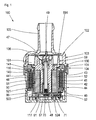
- FIG. 1 shows a sectional view through a centrifugal pump 100 according to the invention, comprising a pump housing 102, comprising a first housing part 103 and a second housing part 104 adjoining it.
- a motor housing part 44 delimits a drying space which is defined by a stator (40) of an electronically commutated DC motor his control electronics is filled.
- the motor housing part 44 connects to the second housing part 102 and.
- the first and the second housing part 103, 104 define a wet space 101 of the centrifugal pump.
- the second housing part 104 is formed integrally with a containment shell 116 which divides the wet space 101 from a drying space 99.
- the wet room 101 includes an axle 49 which is fixedly installed between a cradle-side axle receptacle 48 and an intake-side axle receptacle 47. A knurling at the axis end prevents rotation of the axis 49 during pump operation.
- a fixed bearing 54 is rotatably mounted, which is pressed in a hollow shaft 51 of the rotor 50.
- the shaft 51 is integral with a pump impeller 59 which includes a plurality of approximately spirally shaped wings 591 for the fluid delivery.
- the end faces of the fixed bearing 54 can be supported axially with the interposition of thrust washers against the gap-side axle receptacle 48 and against the intake-side axle receptacle 47.
- a hollow cylindrical ferrite magnet 52 is adhered to the hollow shaft 51, using an elastic adhesive which is inserted into four or five axially parallel grooves 511 formed in the hollow shaft.
- the drying chamber 99 contains the stator 40 of the electronically commutated DC motor 10, which is designed in the form of a hollow cylindrical stator winding 41, wherein the magnetic field is guided in operation via claw poles in an alternating manner to the periphery of the can 116 and with the hollow cylindrical permanent magnet 52 in the wet space 101st interacts.
- the magnetic circuit is closed by a return ring 43, which is connected to the claw poles 42.
- the claw poles 42 are provided by encapsulation with an insulating body 46 which connects the claw poles 42 mechanically but not magnetically.
- the stator 40 has four pole pairs in the present example.
- the Isolierstoff Sciences 46 is geometrically shaped so that the winding wires of the stator winding 41 with Klemmschneid brieflye having contact pins 62 are connected, said Klemmschneid brieflye are mechanically fastened in Isolierstoff emotions 46.
- the contact pins 62 are formed as combination contacts and pressed at its end opposite the clamping cutting contact 63 in a printed circuit board 61 and thus contacted with this.
- the contact pins 62 contain one or two deformable press-fit zones for this purpose.
- the circuit board 61 includes a Hall sensor 71, an integrated circuit 70 for the wiring of the stator winding, a PTC for the winding protection and plug pins 64 for the power supply.
- the motor housing part 44 includes a connector housing 65 in which the connector pins 64 are arranged.
- Conductor tracks which serve for contacting components to be cooled, are dimensioned such that, for easier heat dissipation, conductor tracks 66 which are as wide as possible are provided on the printed circuit board 61.
- the different conductor tracks 66 are of different widths, depending on how much heat is generated in the component connection to be contacted.
- a longitudinal groove is formed as a cooling channel between a bottom 117 of the gap pot 116 and the pump impeller 59, which forces a continuous circulation of the fluid also in the interior of the containment shell 116.
- the printed circuit board is arranged between an end face 45 of the motor housing 44 and the bottom 117 of the can 116 and held in heat-conducting contact with the bottom 117 via the heat-conducting film 67.
- the first housing part 103 has a first flange 130 and a first adjoining ring 131.
- the second housing part 104 has a second flange 140 and a second adjoining ring 141.
- the motor housing part has a third ring 441.
- the second flange 140 and the second ring 141 together form a T-shape in cross-section.
- the first sealing region is located on the radially outer side of the first ring 131 on the first housing part 103.
- Opposite on the radially inner side of the second ring 141 and the second housing part 104 is the second sealing region 144.
- the third sealing region 145 is located on the radially outer side of the third ring 441 and the motor housing part 44.
- the second housing part 104 consists of one for laser light of one wavelength or a wavelength range permeable material.
- the first housing part 103 and the motor housing part 44 are made of a material absorbing the same laser light. This allows a laser beam without heating the transparent material to a seam lead. There the beam meets material, which absorbs the light and converts it to heat, causing the plastic to melt and intimately bond with the adjacent material.
- the welding apparatus may comprise two individual lasers, one weld being made with one laser beam at a time, or may comprise a single laser whose output beam is split by a beam splitter into two beams, each of which produces one of the welds.
- the laser beams are directed radially onto the pump housing.
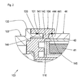
- FIG. 2 shows an enlarged detail of the connection region of the first housing part 103 with the second housing part 104 and between the second housing part 104 and the motor housing part 44.
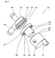
- the first housing part 103 has an intake nozzle 105, a discharge nozzle 106.
- the first flange 130 with the first ring 131 and the first seal portion 133 adjoining thereto, the second housing portion 104 including the containment shell 116, the second flange 140 and the second ring 141 are on the inside thereof the second seal portion 144 and the third seal portion 145, and the motor housing portion 44 including the third ring 441 and the fourth seal portion 444 can be seen.
- the first ring 131 and the second ring 141, and the second ring 141 and the third ring 441 are coordinated so that they are slightly tapered, so that after the axial joining and before welding already results in a non-positive connection.
Landscapes
- Engineering & Computer Science (AREA)
- Mechanical Engineering (AREA)
- General Engineering & Computer Science (AREA)
- Physics & Mathematics (AREA)
- Optics & Photonics (AREA)
- Health & Medical Sciences (AREA)
- Electromagnetism (AREA)
- Toxicology (AREA)
- Structures Of Non-Positive Displacement Pumps (AREA)
Applications Claiming Priority (1)
| Application Number | Priority Date | Filing Date | Title |
|---|---|---|---|
| DE102006021240A DE102006021240B4 (de) | 2006-04-28 | 2006-04-28 | Kreiselpumpe |
Publications (3)
| Publication Number | Publication Date |
|---|---|
| EP1850014A2 true EP1850014A2 (fr) | 2007-10-31 |
| EP1850014A3 EP1850014A3 (fr) | 2008-06-04 |
| EP1850014B1 EP1850014B1 (fr) | 2009-12-23 |
Family
ID=38283086
Family Applications (1)
| Application Number | Title | Priority Date | Filing Date |
|---|---|---|---|
| EP07005219A Active EP1850014B1 (fr) | 2006-04-28 | 2007-03-14 | Pompe centrifuge |
Country Status (5)
| Country | Link |
|---|---|
| US (1) | US8002522B2 (fr) |
| EP (1) | EP1850014B1 (fr) |
| AT (1) | ATE453054T1 (fr) |
| DE (2) | DE102006021240B4 (fr) |
| ES (1) | ES2334460T3 (fr) |
Cited By (1)
| Publication number | Priority date | Publication date | Assignee | Title |
|---|---|---|---|---|
| DE102010029978A1 (de) | 2010-06-11 | 2011-12-15 | Robert Bosch Gmbh | Pumpeneinrichtung |
Families Citing this family (66)
| Publication number | Priority date | Publication date | Assignee | Title |
|---|---|---|---|---|
| EP1922045B1 (fr) | 2005-09-07 | 2012-11-07 | Tyco Healthcare Group LP | Pansement pour plaies autonome muni d'une micropompe |
| EP1922095A2 (fr) | 2005-09-07 | 2008-05-21 | Tyco Healthcare Group LP | Pansement de plaies avec un reservoir a vide |
| US7779625B2 (en) | 2006-05-11 | 2010-08-24 | Kalypto Medical, Inc. | Device and method for wound therapy |
| US9820888B2 (en) | 2006-09-26 | 2017-11-21 | Smith & Nephew, Inc. | Wound dressing |
| DE102007010050A1 (de) * | 2007-03-01 | 2008-09-04 | Continental Automotive Gmbh | Kreiselpumpe mit einem Spiralgehäuse |
| ES2555204T3 (es) | 2007-11-21 | 2015-12-29 | T.J. Smith & Nephew Limited | Dispositivo de succión y venda |
| ES2776709T3 (es) | 2007-11-21 | 2020-07-31 | Smith & Nephew | Apósito para heridas |
| MX2010005553A (es) | 2007-11-21 | 2010-06-01 | Smith & Nephew | Aposito para heridas. |
| GB0722820D0 (en) | 2007-11-21 | 2008-01-02 | Smith & Nephew | Vacuum assisted wound dressing |
| US8298200B2 (en) | 2009-06-01 | 2012-10-30 | Tyco Healthcare Group Lp | System for providing continual drainage in negative pressure wound therapy |
| US9199012B2 (en) | 2008-03-13 | 2015-12-01 | Smith & Nephew, Inc. | Shear resistant wound dressing for use in vacuum wound therapy |
| US20090234306A1 (en) | 2008-03-13 | 2009-09-17 | Tyco Healthcare Group Lp | Vacuum wound therapy wound dressing with variable performance zones |
| US9414968B2 (en) | 2008-09-05 | 2016-08-16 | Smith & Nephew, Inc. | Three-dimensional porous film contact layer with improved wound healing |
| WO2011022557A2 (fr) * | 2009-08-19 | 2011-02-24 | Aspen Motion Technologies, Inc. D/B/A | Ensemble pompe à entraînement magnétique avec moteur intégré |
| DK2515961T3 (da) | 2009-12-22 | 2019-07-15 | Smith & Nephew Inc | Apparatuses and methods for negative pressure wound therapy |
| US9061095B2 (en) | 2010-04-27 | 2015-06-23 | Smith & Nephew Plc | Wound dressing and method of use |
| DE102010019502B4 (de) * | 2010-05-06 | 2023-03-23 | Bühler Motor GmbH | Pumpe mit integriertem elektronisch kommutierten Gleichstrommotor |
| DE102010034563A1 (de) * | 2010-08-17 | 2012-02-23 | Bühler Motor GmbH | Elektronisch kommutierter Gleichstrommotor für eine Flüssigkeitspumpe |
| GB201014074D0 (en) | 2010-08-24 | 2010-10-06 | Dyson Technology Ltd | Rotor for an electrical machine |
| GB201014073D0 (en) | 2010-08-24 | 2010-10-06 | Dyson Technology Ltd | Rotor core assembly |
| JP6078472B2 (ja) | 2010-11-25 | 2017-02-08 | スミス アンド ネフュー ピーエルシーSmith & Nephew Public Limited Company | 組成物i−iiおよび生成物ならびにそれらの使用 |
| GB201020005D0 (en) | 2010-11-25 | 2011-01-12 | Smith & Nephew | Composition 1-1 |
| DE102011004149B4 (de) * | 2011-02-15 | 2021-03-25 | Bühler Motor GmbH | Stator eines Klauenpolmotors |
| GB201108229D0 (en) | 2011-05-17 | 2011-06-29 | Smith & Nephew | Tissue healing |
| JP5798895B2 (ja) * | 2011-11-22 | 2015-10-21 | アスモ株式会社 | 電動ポンプ |
| US20150159066A1 (en) | 2011-11-25 | 2015-06-11 | Smith & Nephew Plc | Composition, apparatus, kit and method and uses thereof |
| JP5987331B2 (ja) * | 2012-02-02 | 2016-09-07 | 株式会社ジェイテクト | 電動オイルポンプ装置 |
| US9901664B2 (en) | 2012-03-20 | 2018-02-27 | Smith & Nephew Plc | Controlling operation of a reduced pressure therapy system based on dynamic duty cycle threshold determination |
| US20170082070A1 (en) * | 2012-04-17 | 2017-03-23 | Timothy J. Miller | Turbopump with a single piece housing and a smooth enamel glass surface |
| CN107095739B (zh) | 2012-05-23 | 2020-11-13 | 史密夫及内修公开有限公司 | 用于负压伤口治疗的装置和方法 |
| HUE033329T2 (en) | 2012-08-01 | 2017-11-28 | Smith & Nephew | Wound dressing |
| EP2968648B1 (fr) | 2013-03-15 | 2020-12-23 | Smith & Nephew plc | Pansement de plaie et procédé de traitement |
| US20160120706A1 (en) | 2013-03-15 | 2016-05-05 | Smith & Nephew Plc | Wound dressing sealant and use thereof |
| EP2968647B1 (fr) | 2013-03-15 | 2022-06-29 | Smith & Nephew plc | Scellement de pansement et son utilisation |
| US10695226B2 (en) | 2013-03-15 | 2020-06-30 | Smith & Nephew Plc | Wound dressing and method of treatment |
| PL2976532T3 (pl) | 2013-03-19 | 2018-10-31 | Flow Control Llc. | Pompa o niskim profilu z możliwością montażu w różnych konfiguracjach |
| USD701246S1 (en) | 2013-07-01 | 2014-03-18 | Flow Control Llc. | Low profile pump |
| DE102013223713B4 (de) * | 2013-11-20 | 2020-11-26 | Continental Automotive Gmbh | Baugruppe für ein Kraftfahrzeug, insbesondere Ventilbaugruppe einer Scheibenwaschanlage und Verfahren zur Erzeugung einer solchen Baugruppe |
| EP3157484B1 (fr) | 2014-06-18 | 2020-02-26 | Smith & Nephew plc | Pansement |
| FR3022596B1 (fr) * | 2014-06-19 | 2019-03-29 | Akwel | Pompe et procede d'assemblage d'une telle pompe |
| DE102014113508A1 (de) * | 2014-09-18 | 2016-03-24 | Sysko Ag | Schwingankerpumpe |
| AU2015370583B2 (en) | 2014-12-22 | 2020-08-20 | Smith & Nephew Plc | Negative pressure wound therapy apparatus and methods |
| CN105221441A (zh) * | 2015-09-18 | 2016-01-06 | 河南省西峡汽车水泵股份有限公司 | 一种低能耗高寿命的汽车电动水泵 |
| JP6556580B2 (ja) * | 2015-09-30 | 2019-08-07 | 日本電産サンキョー株式会社 | モータおよびモータの製造方法 |
| JP7044705B2 (ja) | 2015-12-30 | 2022-03-30 | スミス アンド ネフュー ピーエルシー | 負圧創傷治療装置 |
| WO2017115146A1 (fr) | 2015-12-30 | 2017-07-06 | Smith & Nephew Plc | Pansement de thérapie par pression négative pour les plaies |
| JP1586116S (fr) | 2016-02-29 | 2017-09-19 | ||
| US11771820B2 (en) | 2016-03-04 | 2023-10-03 | Smith & Nephew Plc | Negative pressure wound therapy apparatus for post breast surgery wounds |
| DE102016206396A1 (de) | 2016-04-15 | 2017-10-19 | Bühler Motor GmbH | Werkstück und Verfahren zur Herstellung des Werkstücks |
| DE102016206406A1 (de) * | 2016-04-15 | 2017-10-19 | Bühler Motor GmbH | Pumpenmotor mit einem Spalttopf |
| DE102016005102A1 (de) | 2016-04-27 | 2017-11-02 | Wilo Se | Kommunikationseinrichtung, insbesondere für eine Kreiselpumpe |
| DE102016118627B4 (de) * | 2016-09-30 | 2019-11-07 | Nidec Gpm Gmbh | Pumpe für flüssige Fördermedien mit schwimmender Rotorlagerung |
| US11806217B2 (en) | 2016-12-12 | 2023-11-07 | Smith & Nephew Plc | Wound dressing |
| JP6988154B2 (ja) * | 2017-05-09 | 2022-01-05 | 株式会社デンソー | 電動ポンプ |
| CA3065380A1 (fr) | 2017-06-14 | 2018-12-20 | T.J.Smith & Nephew, Limited | Appareil de traitement de plaie a pression negative |
| US11389582B2 (en) | 2017-09-29 | 2022-07-19 | T.J. Smith And Nephew, Limited | Negative pressure wound therapy apparatus with removable panels |
| GB201811449D0 (en) | 2018-07-12 | 2018-08-29 | Smith & Nephew | Apparatuses and methods for negative pressure wound therapy |
| CN112524048A (zh) * | 2019-09-18 | 2021-03-19 | 广东德昌电机有限公司 | 液体泵 |
| GB202000574D0 (en) | 2020-01-15 | 2020-02-26 | Smith & Nephew | Fluidic connectors for negative pressure wound therapy |
| GB202001212D0 (en) | 2020-01-29 | 2020-03-11 | Smith & Nephew | Systems and methods for measuring and tracking wound volume |
| CN114542478A (zh) * | 2020-11-27 | 2022-05-27 | 浙江三花汽车零部件有限公司 | 泵装置 |
| DE102021122216A1 (de) | 2021-08-27 | 2023-03-02 | KSB SE & Co. KGaA | Geschlossene Dickschicht für Pumpen |
| US12092115B2 (en) * | 2022-05-26 | 2024-09-17 | Cooper-Standard Automotive Inc. | Pump with rotary valve and fluid submersible motor |
| US11781566B1 (en) * | 2022-11-23 | 2023-10-10 | Coavis | Water pump and manufacturing method thereof |
| DE102024131214A1 (de) | 2024-10-25 | 2026-04-30 | Mahle International Gmbh | Fluidpumpe |
| DE102024131326A1 (de) | 2024-10-28 | 2026-04-30 | Mahle International Gmbh | Fluidpumpe |
Citations (4)
| Publication number | Priority date | Publication date | Assignee | Title |
|---|---|---|---|---|
| DE19956380C1 (de) | 1999-11-24 | 2001-01-04 | Bosch Gmbh Robert | Flüssigkeitspumpe mit einem Motorgehäuse und Verfahren zur Herstellung eines Motorgehäuses |
| DE10062446A1 (de) | 2000-12-14 | 2002-07-11 | Siemens Ag | Saugstrahlpumpe und Verfahren zur Fertigung einer Saugstrahlpumpe |
| DE202004010890U1 (de) | 2003-07-16 | 2004-09-30 | Ebm-Papst St. Georgen Gmbh & Co. Kg | Minilüfter |
| WO2005052377A1 (fr) | 2003-11-27 | 2005-06-09 | Daikin Industries, Ltd. | Roue a aubes pour soufflante centrifuge et soufflante centrifuge equipee d'une telle roue |
Family Cites Families (4)
| Publication number | Priority date | Publication date | Assignee | Title |
|---|---|---|---|---|
| DE3145409A1 (de) * | 1981-11-16 | 1983-05-26 | Philipp Hilge Gmbh, 6501 Bodenheim | Spiralgehaeuse fuer stroemungsmaschinen und ihre herstellung |
| DE4438747A1 (de) * | 1994-10-29 | 1996-05-02 | Pierburg Gmbh | Elektrisch angetriebene Luftpumpe |
| LU90784B1 (en) * | 2001-05-29 | 2002-12-02 | Delphi Tech Inc | Process for transmission laser welding of plastic parts |
| JP4790466B2 (ja) * | 2006-03-28 | 2011-10-12 | ダイキン工業株式会社 | レーザー溶着方法、レーザー溶着装置、及び送風機用羽根車の製造方法 |
-
2006
- 2006-04-28 DE DE102006021240A patent/DE102006021240B4/de not_active Expired - Fee Related
-
2007
- 2007-03-14 DE DE502007002376T patent/DE502007002376D1/de active Active
- 2007-03-14 EP EP07005219A patent/EP1850014B1/fr active Active
- 2007-03-14 ES ES07005219T patent/ES2334460T3/es active Active
- 2007-03-14 AT AT07005219T patent/ATE453054T1/de active
- 2007-04-27 US US11/790,817 patent/US8002522B2/en active Active
Patent Citations (4)
| Publication number | Priority date | Publication date | Assignee | Title |
|---|---|---|---|---|
| DE19956380C1 (de) | 1999-11-24 | 2001-01-04 | Bosch Gmbh Robert | Flüssigkeitspumpe mit einem Motorgehäuse und Verfahren zur Herstellung eines Motorgehäuses |
| DE10062446A1 (de) | 2000-12-14 | 2002-07-11 | Siemens Ag | Saugstrahlpumpe und Verfahren zur Fertigung einer Saugstrahlpumpe |
| DE202004010890U1 (de) | 2003-07-16 | 2004-09-30 | Ebm-Papst St. Georgen Gmbh & Co. Kg | Minilüfter |
| WO2005052377A1 (fr) | 2003-11-27 | 2005-06-09 | Daikin Industries, Ltd. | Roue a aubes pour soufflante centrifuge et soufflante centrifuge equipee d'une telle roue |
Cited By (1)
| Publication number | Priority date | Publication date | Assignee | Title |
|---|---|---|---|---|
| DE102010029978A1 (de) | 2010-06-11 | 2011-12-15 | Robert Bosch Gmbh | Pumpeneinrichtung |
Also Published As
| Publication number | Publication date |
|---|---|
| ATE453054T1 (de) | 2010-01-15 |
| DE502007002376D1 (de) | 2010-02-04 |
| EP1850014B1 (fr) | 2009-12-23 |
| US20080031748A1 (en) | 2008-02-07 |
| DE102006021240A1 (de) | 2007-11-08 |
| DE102006021240B4 (de) | 2008-01-31 |
| US8002522B2 (en) | 2011-08-23 |
| EP1850014A3 (fr) | 2008-06-04 |
| ES2334460T3 (es) | 2010-03-10 |
Similar Documents
| Publication | Publication Date | Title |
|---|---|---|
| EP1850014B1 (fr) | Pompe centrifuge | |
| EP1850453B1 (fr) | Rotor à aimant permanent | |
| DE102006021242B4 (de) | Elektromotor | |
| DE102007016255B4 (de) | Kreiselpumpe | |
| EP2500575B1 (fr) | Pompe de recirculation de chauffage | |
| EP1850015A2 (fr) | Pompe centrifuge | |
| EP3913771B1 (fr) | Moteur électrique | |
| EP1850448A1 (fr) | Moteur éléctrique | |
| DE4122529B4 (de) | Elektronisch kommutierter Antriebsmotor | |
| EP2500576A1 (fr) | Pompe de recirculation de chauffage | |
| WO2012123235A1 (fr) | Pompe de circulation de chauffage | |
| EP0860930A2 (fr) | Moteur électrique pour une pompe ou un ventilateur | |
| EP2500574A1 (fr) | Pompe de recirculation de chauffage | |
| DE4331803A1 (de) | Elektronisch kommutierter Elektromotor | |
| EP3158626A2 (fr) | Moteur électrique pourvu d'un rotor, d'un stator et d'un boîtier électronique et roue de ventilateur pour moteur électrique | |
| DE102009029069A1 (de) | Zweistufige Kreiselpumpe | |
| EP4483477A1 (fr) | Moteur sans balai et procédé d'installation d'un moteur sans balai | |
| DE112009000856T5 (de) | Rotoranordnung mit Sintermagnetkernbaugruppe | |
| EP0734607B1 (fr) | Machine electrique, notamment alternateur a courant triphase | |
| EP1850449A2 (fr) | Moteur électrique | |
| EP3391509B1 (fr) | Moteur électrique | |
| EP3729610B1 (fr) | Ensemble moteur avec un bidon | |
| DE102005032398A1 (de) | Anordnung mit einem Elektromotor |
Legal Events
| Date | Code | Title | Description |
|---|---|---|---|
| PUAI | Public reference made under article 153(3) epc to a published international application that has entered the european phase |
Free format text: ORIGINAL CODE: 0009012 |
|
| AK | Designated contracting states |
Kind code of ref document: A2 Designated state(s): AT BE BG CH CY CZ DE DK EE ES FI FR GB GR HU IE IS IT LI LT LU LV MC MT NL PL PT RO SE SI SK TR |
|
| AX | Request for extension of the european patent |
Extension state: AL BA HR MK YU |
|
| PUAL | Search report despatched |
Free format text: ORIGINAL CODE: 0009013 |
|
| AK | Designated contracting states |
Kind code of ref document: A3 Designated state(s): AT BE BG CH CY CZ DE DK EE ES FI FR GB GR HU IE IS IT LI LT LU LV MC MT NL PL PT RO SE SI SK TR |
|
| AX | Request for extension of the european patent |
Extension state: AL BA HR MK RS |
|
| RIC1 | Information provided on ipc code assigned before grant |
Ipc: B29C 65/00 20060101ALI20080430BHEP Ipc: B29C 65/16 20060101ALI20080430BHEP Ipc: F04D 29/42 20060101ALI20080430BHEP Ipc: F04D 29/62 20060101ALI20080430BHEP Ipc: F04D 29/02 20060101AFI20070802BHEP |
|
| 17P | Request for examination filed |
Effective date: 20080610 |
|
| 17Q | First examination report despatched |
Effective date: 20080711 |
|
| AKX | Designation fees paid |
Designated state(s): AT BE BG CH CY CZ DE DK EE ES FI FR GB GR HU IE IS IT LI LT LU LV MC MT NL PL PT RO SE SI SK TR |
|
| GRAP | Despatch of communication of intention to grant a patent |
Free format text: ORIGINAL CODE: EPIDOSNIGR1 |
|
| GRAS | Grant fee paid |
Free format text: ORIGINAL CODE: EPIDOSNIGR3 |
|
| GRAA | (expected) grant |
Free format text: ORIGINAL CODE: 0009210 |
|
| AK | Designated contracting states |
Kind code of ref document: B1 Designated state(s): AT BE BG CH CY CZ DE DK EE ES FI FR GB GR HU IE IS IT LI LT LU LV MC MT NL PL PT RO SE SI SK TR |
|
| REG | Reference to a national code |
Ref country code: GB Ref legal event code: FG4D Free format text: NOT ENGLISH |
|
| REG | Reference to a national code |
Ref country code: CH Ref legal event code: EP |
|
| REG | Reference to a national code |
Ref country code: IE Ref legal event code: FG4D |
|
| REF | Corresponds to: |
Ref document number: 502007002376 Country of ref document: DE Date of ref document: 20100204 Kind code of ref document: P |
|
| REG | Reference to a national code |
Ref country code: ES Ref legal event code: FG2A Ref document number: 2334460 Country of ref document: ES Kind code of ref document: T3 |
|
| REG | Reference to a national code |
Ref country code: NL Ref legal event code: VDEP Effective date: 20091223 |
|
| PG25 | Lapsed in a contracting state [announced via postgrant information from national office to epo] |
Ref country code: LT Free format text: LAPSE BECAUSE OF FAILURE TO SUBMIT A TRANSLATION OF THE DESCRIPTION OR TO PAY THE FEE WITHIN THE PRESCRIBED TIME-LIMIT Effective date: 20091223 Ref country code: FI Free format text: LAPSE BECAUSE OF FAILURE TO SUBMIT A TRANSLATION OF THE DESCRIPTION OR TO PAY THE FEE WITHIN THE PRESCRIBED TIME-LIMIT Effective date: 20091223 Ref country code: SE Free format text: LAPSE BECAUSE OF FAILURE TO SUBMIT A TRANSLATION OF THE DESCRIPTION OR TO PAY THE FEE WITHIN THE PRESCRIBED TIME-LIMIT Effective date: 20091223 |
|
| LTIE | Lt: invalidation of european patent or patent extension |
Effective date: 20091223 |
|
| PG25 | Lapsed in a contracting state [announced via postgrant information from national office to epo] |
Ref country code: PL Free format text: LAPSE BECAUSE OF FAILURE TO SUBMIT A TRANSLATION OF THE DESCRIPTION OR TO PAY THE FEE WITHIN THE PRESCRIBED TIME-LIMIT Effective date: 20091223 Ref country code: SI Free format text: LAPSE BECAUSE OF FAILURE TO SUBMIT A TRANSLATION OF THE DESCRIPTION OR TO PAY THE FEE WITHIN THE PRESCRIBED TIME-LIMIT Effective date: 20091223 Ref country code: LV Free format text: LAPSE BECAUSE OF FAILURE TO SUBMIT A TRANSLATION OF THE DESCRIPTION OR TO PAY THE FEE WITHIN THE PRESCRIBED TIME-LIMIT Effective date: 20091223 |
|
| REG | Reference to a national code |
Ref country code: IE Ref legal event code: FD4D |
|
| PG25 | Lapsed in a contracting state [announced via postgrant information from national office to epo] |
Ref country code: NL Free format text: LAPSE BECAUSE OF FAILURE TO SUBMIT A TRANSLATION OF THE DESCRIPTION OR TO PAY THE FEE WITHIN THE PRESCRIBED TIME-LIMIT Effective date: 20091223 Ref country code: EE Free format text: LAPSE BECAUSE OF FAILURE TO SUBMIT A TRANSLATION OF THE DESCRIPTION OR TO PAY THE FEE WITHIN THE PRESCRIBED TIME-LIMIT Effective date: 20091223 Ref country code: RO Free format text: LAPSE BECAUSE OF FAILURE TO SUBMIT A TRANSLATION OF THE DESCRIPTION OR TO PAY THE FEE WITHIN THE PRESCRIBED TIME-LIMIT Effective date: 20091223 Ref country code: PT Free format text: LAPSE BECAUSE OF FAILURE TO SUBMIT A TRANSLATION OF THE DESCRIPTION OR TO PAY THE FEE WITHIN THE PRESCRIBED TIME-LIMIT Effective date: 20100423 Ref country code: BG Free format text: LAPSE BECAUSE OF FAILURE TO SUBMIT A TRANSLATION OF THE DESCRIPTION OR TO PAY THE FEE WITHIN THE PRESCRIBED TIME-LIMIT Effective date: 20100323 Ref country code: IS Free format text: LAPSE BECAUSE OF FAILURE TO SUBMIT A TRANSLATION OF THE DESCRIPTION OR TO PAY THE FEE WITHIN THE PRESCRIBED TIME-LIMIT Effective date: 20100423 |
|
| PG25 | Lapsed in a contracting state [announced via postgrant information from national office to epo] |
Ref country code: CZ Free format text: LAPSE BECAUSE OF FAILURE TO SUBMIT A TRANSLATION OF THE DESCRIPTION OR TO PAY THE FEE WITHIN THE PRESCRIBED TIME-LIMIT Effective date: 20091223 Ref country code: SK Free format text: LAPSE BECAUSE OF FAILURE TO SUBMIT A TRANSLATION OF THE DESCRIPTION OR TO PAY THE FEE WITHIN THE PRESCRIBED TIME-LIMIT Effective date: 20091223 |
|
| BERE | Be: lapsed |
Owner name: BUHLER MOTOR G.M.B.H. Effective date: 20100331 |
|
| PG25 | Lapsed in a contracting state [announced via postgrant information from national office to epo] |
Ref country code: IE Free format text: LAPSE BECAUSE OF FAILURE TO SUBMIT A TRANSLATION OF THE DESCRIPTION OR TO PAY THE FEE WITHIN THE PRESCRIBED TIME-LIMIT Effective date: 20091223 Ref country code: GR Free format text: LAPSE BECAUSE OF FAILURE TO SUBMIT A TRANSLATION OF THE DESCRIPTION OR TO PAY THE FEE WITHIN THE PRESCRIBED TIME-LIMIT Effective date: 20100324 Ref country code: CY Free format text: LAPSE BECAUSE OF FAILURE TO SUBMIT A TRANSLATION OF THE DESCRIPTION OR TO PAY THE FEE WITHIN THE PRESCRIBED TIME-LIMIT Effective date: 20091223 Ref country code: MC Free format text: LAPSE BECAUSE OF NON-PAYMENT OF DUE FEES Effective date: 20100331 |
|
| PLBE | No opposition filed within time limit |
Free format text: ORIGINAL CODE: 0009261 |
|
| STAA | Information on the status of an ep patent application or granted ep patent |
Free format text: STATUS: NO OPPOSITION FILED WITHIN TIME LIMIT |
|
| 26N | No opposition filed |
Effective date: 20100924 |
|
| PG25 | Lapsed in a contracting state [announced via postgrant information from national office to epo] |
Ref country code: DK Free format text: LAPSE BECAUSE OF FAILURE TO SUBMIT A TRANSLATION OF THE DESCRIPTION OR TO PAY THE FEE WITHIN THE PRESCRIBED TIME-LIMIT Effective date: 20091223 |
|
| PG25 | Lapsed in a contracting state [announced via postgrant information from national office to epo] |
Ref country code: BE Free format text: LAPSE BECAUSE OF NON-PAYMENT OF DUE FEES Effective date: 20100331 |
|
| PG25 | Lapsed in a contracting state [announced via postgrant information from national office to epo] |
Ref country code: IT Free format text: LAPSE BECAUSE OF FAILURE TO SUBMIT A TRANSLATION OF THE DESCRIPTION OR TO PAY THE FEE WITHIN THE PRESCRIBED TIME-LIMIT Effective date: 20091223 |
|
| PG25 | Lapsed in a contracting state [announced via postgrant information from national office to epo] |
Ref country code: MT Free format text: LAPSE BECAUSE OF FAILURE TO SUBMIT A TRANSLATION OF THE DESCRIPTION OR TO PAY THE FEE WITHIN THE PRESCRIBED TIME-LIMIT Effective date: 20091223 |
|
| REG | Reference to a national code |
Ref country code: CH Ref legal event code: PL |
|
| PG25 | Lapsed in a contracting state [announced via postgrant information from national office to epo] |
Ref country code: CH Free format text: LAPSE BECAUSE OF NON-PAYMENT OF DUE FEES Effective date: 20110331 Ref country code: LI Free format text: LAPSE BECAUSE OF NON-PAYMENT OF DUE FEES Effective date: 20110331 |
|
| PG25 | Lapsed in a contracting state [announced via postgrant information from national office to epo] |
Ref country code: HU Free format text: LAPSE BECAUSE OF FAILURE TO SUBMIT A TRANSLATION OF THE DESCRIPTION OR TO PAY THE FEE WITHIN THE PRESCRIBED TIME-LIMIT Effective date: 20100624 Ref country code: LU Free format text: LAPSE BECAUSE OF NON-PAYMENT OF DUE FEES Effective date: 20100314 |
|
| PG25 | Lapsed in a contracting state [announced via postgrant information from national office to epo] |
Ref country code: TR Free format text: LAPSE BECAUSE OF FAILURE TO SUBMIT A TRANSLATION OF THE DESCRIPTION OR TO PAY THE FEE WITHIN THE PRESCRIBED TIME-LIMIT Effective date: 20091223 |
|
| REG | Reference to a national code |
Ref country code: AT Ref legal event code: MM01 Ref document number: 453054 Country of ref document: AT Kind code of ref document: T Effective date: 20120314 |
|
| PG25 | Lapsed in a contracting state [announced via postgrant information from national office to epo] |
Ref country code: AT Free format text: LAPSE BECAUSE OF NON-PAYMENT OF DUE FEES Effective date: 20120314 |
|
| REG | Reference to a national code |
Ref country code: FR Ref legal event code: PLFP Year of fee payment: 10 |
|
| REG | Reference to a national code |
Ref country code: FR Ref legal event code: PLFP Year of fee payment: 11 |
|
| REG | Reference to a national code |
Ref country code: FR Ref legal event code: PLFP Year of fee payment: 12 |
|
| P01 | Opt-out of the competence of the unified patent court (upc) registered |
Effective date: 20230920 |
|
| PGFP | Annual fee paid to national office [announced via postgrant information from national office to epo] |
Ref country code: ES Payment date: 20250404 Year of fee payment: 19 |
|
| PGFP | Annual fee paid to national office [announced via postgrant information from national office to epo] |
Ref country code: GB Payment date: 20260317 Year of fee payment: 20 |
|
| PGFP | Annual fee paid to national office [announced via postgrant information from national office to epo] |
Ref country code: DE Payment date: 20260312 Year of fee payment: 20 |
|
| PGFP | Annual fee paid to national office [announced via postgrant information from national office to epo] |
Ref country code: FR Payment date: 20260224 Year of fee payment: 20 |