EP1850042A2 - Manueller Vorrangsteuerungsmechanismus für ein winkeliges Tellerventil - Google Patents
Manueller Vorrangsteuerungsmechanismus für ein winkeliges Tellerventil Download PDFInfo
- Publication number
- EP1850042A2 EP1850042A2 EP07106909A EP07106909A EP1850042A2 EP 1850042 A2 EP1850042 A2 EP 1850042A2 EP 07106909 A EP07106909 A EP 07106909A EP 07106909 A EP07106909 A EP 07106909A EP 1850042 A2 EP1850042 A2 EP 1850042A2
- Authority
- EP
- European Patent Office
- Prior art keywords
- valve
- lock
- coupled
- shaft
- valve body
- Prior art date
- Legal status (The legal status is an assumption and is not a legal conclusion. Google has not performed a legal analysis and makes no representation as to the accuracy of the status listed.)
- Withdrawn
Links
Images
Classifications
-
- F—MECHANICAL ENGINEERING; LIGHTING; HEATING; WEAPONS; BLASTING
- F16—ENGINEERING ELEMENTS AND UNITS; GENERAL MEASURES FOR PRODUCING AND MAINTAINING EFFECTIVE FUNCTIONING OF MACHINES OR INSTALLATIONS; THERMAL INSULATION IN GENERAL
- F16K—VALVES; TAPS; COCKS; ACTUATING-FLOATS; DEVICES FOR VENTING OR AERATING
- F16K31/00—Actuating devices; Operating means; Releasing devices
- F16K31/12—Actuating devices; Operating means; Releasing devices actuated by fluid
- F16K31/14—Actuating devices; Operating means; Releasing devices actuated by fluid for mounting on, or in combination with, hand-actuated valves
- F16K31/143—Actuating devices; Operating means; Releasing devices actuated by fluid for mounting on, or in combination with, hand-actuated valves the fluid acting on a piston
Definitions
- the present invention generally relates to an assembly for a valve, and more particularly relates to an assembly for manually opening a valve and locking the valve in an open position.
- Valves are used to control gases or other fluids in various types of apparatus and vehicles, such as aircraft.
- valves may be used to control the supply of bleed air to aircraft anti-icing systems, among various other uses in aircraft and other types of apparatus and vehicles.
- aircraft anti-icing system example valves are typically configured to open automatically via a mechanism such as a spring, and to close automatically though a pneumatic mechanism.
- a mechanism such as a spring
- valves used in aircraft can be subjected to potentially severe temperatures and conditions, it is desirable that such valves are designed to withstand such temperatures and conditions.
- valve assembly capable of withstanding potentially severe temperatures and conditions, for opening a valve, locking the valve in an open position, and providing visual confirmation of the same to the operators of the vehicle or apparatus.
- the valve assembly comprises a valve body, a valve element, a shaft, an engagement stop, an actuator housing, a manual lockout, and a lock.
- the valve body includes an inlet port, an outlet port, and a flow passage extending between the inlet and outlet ports.
- the valve element is disposed within the valve body flow passage, and is movable between a closed position and a full-open position.
- the shaft is coupled to the valve element and extends through the valve body.
- the engagement stop is coupled to, and extends radially from, the shaft.
- the actuator housing is coupled to the valve body and at least partially surrounds the shaft.
- the manual lockout is movably coupled to the actuator housing, and at least partially surrounds the shaft.
- the manual lockout is configured, upon receipt of a torque, to selectively engage and disengage the engagement stop.
- the lock is coupled to the actuator housing.
- the lock is movable between a lock position, in which the lock at least inhibits movement of the manual lockout, and an unlock position, in which the lock allows movement of the manual lockout.
- the valve body assembly comprises a valve body, a valve element, a shaft, an engagement stop, an actuator housing, a manual lockout, and a jam nut.
- the valve body includes an inlet port, an outlet port, and a flow passage extending between the inlet and outlet ports.
- the valve element is disposed within the valve body flow passage, and is movable between a closed position and a full-open position.
- the shaft is coupled to the valve element and extends through the valve body.
- the engagement stop is coupled to, and extends radially from, the shaft.
- the engagement stop comprises a washer and a lock nut disposed against the washer and configured to hold the washer into place.
- the actuator housing is coupled to the valve body and at least partially surrounds the shaft.
- the manual lockout is movably coupled to the actuator housing, and at least partially surrounds the shaft.
- the manual lockout is configured, upon receipt of a torque, to selectively engage and disengage the engagement stop.
- the jam nut is coupled to the actuator housing. The jam nut is movable between a lock position, in which the jam nut at least inhibits movement of the manual lockout, and an unlock position, in which the jam nut allows movement of the manual lockout.
- the valve body assembly comprises a valve body, a valve element, a shaft, an engagement stop, an actuator housing, a manual lockout, a jam nut, and threads.
- the valve body includes an inlet port, an outlet port, and a flow passage extending between the inlet and outlet ports.
- the valve element is disposed within the valve body flow passage, and is movable between a closed position and a full-open position.
- the shaft is coupled to the valve element and extends through the valve body.
- the engagement stop is coupled to, and extends radially from, the shaft.
- the engagement stop comprises a washer and a lock nut disposed against the washer and configured to hold the washer into place.
- the actuator housing is coupled to the valve body and at least partially surrounds the shaft.
- the manual lockout is movably coupled to the actuator housing, and at least partially surrounds the shaft.
- the manual lockout is configured, upon receipt of a torque, to selectively engage and disengage the engagement stop.
- the jam nut is coupled to the actuator housing.
- the jam nut is movable between a lock position in which the jam nut at least inhibits movement of the manual lockout, and an unlock position, in which the jam nut allows movement of the manual lockout.
- the threads are disposed on the manual lockout, and are configured to be coupled with the jam nut to secure the manual lockout into place.
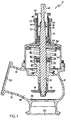
- FIG. 1 depicts a simplified cross section view of a valve assembly for opening a valve and locking the valve in a full-open position.
- FIG. 1 depicts a simplified cross section view of an exemplary embodiment of a valve assembly 10.
- the valve assembly 10 includes a valve body 12, a valve element 14, a shaft 16, an engagement stop 18, an actuator housing 19, a manual lockout 20, and a lock 22.
- the valve assembly 10 also preferably includes a spring 24 and a valve seat 26.
- the valve body 12 has at least an inlet port 28, an outlet port 30, and a flow passage 32 extending between the inlet 28 and outlet 30 ports.
- the inlet port 28, the outlet port 30, and the flow passage 32 allow for the controlled flow of bleed air.
- the valve assembly 10 can influence or control the flow of bleed air from a turbine engine compressor (not shown) to an environmental control system or other anti-icing apparatus (not shown), when bleed air is needed or desired.
- any of numerous different gases or other fluids can flow through a particular valve assembly 10, from any one of numerous different sources, and for any one of numerous different purposes. Regardless of the particular gases or other fluids capable of flowing therethrough, such flow is controlled through movement of the valve element 14, as described below.
- the valve element 14 is disposed within the valve body flow passage 32 and, as mentioned above, controls the flow of fluids, such as bleed air in the aircraft anti-icing system example.
- the valve element 14 is movable between a closed position, in which fluid is at least substantially restricted (and preferably fully restricted) from flowing through the flow passage 32, and a full-open position, in which fluid can freely flow through the flow passage 32.
- FIG. 1 depicts the valve element 14 in a single position, namely the full-open position. Conversely, when the valve element 14 is in the closed position, the valve element 14 seats against the valve seat 26, thereby at least substantially blocking the flow of fluid through the flow passage 32.
- the shaft 16 is coupled to the valve element 14, and extends through the valve body 12 and the actuator housing 19.
- the shaft 16 is used to move the valve element 14 between the closed and full-open position.
- the valve element 14 is biased toward the full-open position via the spring 24.
- the spring 24 at one end rests against the valve body 12, and at the other end rests against a piston 36 that extends radially from the shaft 16.
- the valve 10 is pneumatically moved into the closed position by supplying pressurized air to a cavity 38, via a non-illustrated air source. The pressurized air exerts a downward force on the piston 36.
- valve element 14 may be used to control the flow of any one of numerous different types of fluids, including bleed air and/or any one of Numerous other types of gases or other fluids, and/or combinations thereof.
- the engagement stop 18 is coupled to, and extends radially from, the shaft 16.
- the engagement stop 18 includes at least a washer 40.
- the washer 40 is preferably made of a material, such as a material from the A-286 family of alloys, capable of withstanding high temperatures.
- the washer 40 is also preferably made with an enhanced thickness for withstanding large amounts of pressure.
- the engagement stop 18 also includes a lock nut 42 disposed against the washer 40, and adapted to hold the washer 40 in place.
- the engagement stop 18 can take any one of numerous different configurations.
- the actuator housing 19 is coupled to the valve body 12, and at least partially surrounds the shaft 16.
- the actuator housing 19 and the valve body 12 can be formed separately, and the actuator housing 19 can be bolted, otherwise attached to, or otherwise disposed proximate the valve body 12.
- that actuator housing 19 and the valve body 12 can be formed as a unitary piece.
- the actuator housing 19 can take any one of numerous different configurations. Regardless of the particular configuration, the actuator housing 19 preferably includes a plurality of actuator housing threads 34, as will be discussed further in connection with the manual lockout 20 below.
- the manual lockout 20 is coupled to the actuator housing 19, preferably through a plurality of manual lockout threads 44, disposed on the manual lockout 20, that mate with the valve body threads 34.
- the manual lockout 20 is configured, upon receipt of a torque, to selectively engage and disengage the engagement stop 18.
- the manual lockout 20 upon receipt of a torque, moves upward, out of the actuator housing 19, and contacts the washer 40.
- the manual lockout 20 upon further application of torque, exerts a force on the shaft 16. This in turn results in upward movement of the shaft 16, and the valve element 14 along with the shaft 16, until the valve element 14 is in the full-open position.
- the valve element 14 can then be locked into the full-open position with the lock 22.
- the manual lockout 20 can be coupled to, and engage and disengage, the engagement stop 18 using any one of numerous different mechanisms corresponding with the various possible configurations of the engagement stop 18. Regardless of the various coupling, engaging and disengaging mechanisms, the manual lockout 20 allows for the valve element 14 to be moved into the full-open position when desired, for example in the unlikely event of a failure of the spring 24, which is typically used to move the valve element 14 into the full-open position.
- the lock 22 is coupled to the actuator housing 19, and is movable between a lock position, in which the lock 22 at least inhibits movement of the manual lockout 20, and an unlock position, in which the lock 22 allows movement of the manual lockout 20.
- the lock 22 is implemented using a jam nut.
- the jam nut 22 is threaded onto the manual lockout 20 via a plurality of jam nut threads 46, disposed on the jam nut 22, that mate with the manual lockout threads 44.
- the jam nut 22 can be moved from the lock position to the unlock position by loosening the jam nut 22, and likewise can be moved from the unlock position to the lock position by tightening the jam nut 22.
- the jam nut 22 remains in the tightened, lock position during ordinary operation of the valve assembly 10.
- the jam nut 22 can be moved into the unlock position through loosening of the jam nut 22, thereby allowing movement of the manual lockout 20. Torque can then be applied to the manual lockout 20 to engage the engagement stop 18, and thereby move the shaft 16, and concomitantly the valve element 14, into the full-open position.
- the jam nut 22 can then be tightened into the lock position, thereby restricting movement of the manual lockout 20 and the shaft 16, and in turn locking the valve element 14 in the full-open position.
- valve assembly 10 allows for the valve element 14 to be manually opened and locked into the full-open position, when needed.
- the valve assembly 10 is able to withstand severe temperature, pressure, and other operating conditions, such as conditions potentially existing in an engine nacelle of an aircraft.
- the valve assembly 10 has an additional advantage of providing the operator with visual confirmation when the valve element 14 is locked in the full-open position. Specifically, when the valve element 14 is locked in the full-open position in the embodiment of FIG. 1, there is a portion 48 of the shaft 16 that extends beyond the actuator housing 19 and the manual lockout 20, providing visual confirmation that the valve element 14 is locked in the full-open position.
- the procedures for using the valve assembly 10 may differ.
- some other type of lock 22, other than a jam nut is used, there may be different procedures involved in moving the lock 22 between the lock and unlock positions.
- other procedures may also be involved for using the valve assembly 10 if the engagement stop 18, and/or some other features of the valve assembly 10, take a different configuration than that depicted in FIG. 1.
- the valve assembly 10 may also contain other components, such as a poppet guide and seals for sealing any unwanted openings created after installing the engagement stop 18 and the manual lockout 20, among various other possible components.
Landscapes
- Engineering & Computer Science (AREA)
- General Engineering & Computer Science (AREA)
- Mechanical Engineering (AREA)
- Preventing Unauthorised Actuation Of Valves (AREA)
- Lift Valve (AREA)
Applications Claiming Priority (1)
| Application Number | Priority Date | Filing Date | Title |
|---|---|---|---|
| US11/412,362 US7540468B2 (en) | 2006-04-26 | 2006-04-26 | Angled poppet valve manual override mechanism |
Publications (2)
| Publication Number | Publication Date |
|---|---|
| EP1850042A2 true EP1850042A2 (de) | 2007-10-31 |
| EP1850042A3 EP1850042A3 (de) | 2009-06-17 |
Family
ID=38249238
Family Applications (1)
| Application Number | Title | Priority Date | Filing Date |
|---|---|---|---|
| EP07106909A Withdrawn EP1850042A3 (de) | 2006-04-26 | 2007-04-25 | Manueller Vorrangsteuerungsmechanismus für ein winkeliges Tellerventil |
Country Status (2)
| Country | Link |
|---|---|
| US (1) | US7540468B2 (de) |
| EP (1) | EP1850042A3 (de) |
Cited By (1)
| Publication number | Priority date | Publication date | Assignee | Title |
|---|---|---|---|---|
| CN114165639A (zh) * | 2020-09-11 | 2022-03-11 | 通用电气航空系统有限责任公司 | 阀组件和锁定机构 |
Families Citing this family (1)
| Publication number | Priority date | Publication date | Assignee | Title |
|---|---|---|---|---|
| US9255643B2 (en) | 2011-07-25 | 2016-02-09 | Delaware Capital Formation, Inc. | Integrated pneumatic valve lock |
Family Cites Families (21)
| Publication number | Priority date | Publication date | Assignee | Title |
|---|---|---|---|---|
| US1799143A (en) * | 1929-11-14 | 1931-04-07 | James H Bailey | Choke valve for oil and gas wells |
| US3446241A (en) * | 1967-08-28 | 1969-05-27 | Mojonnier Bros Co | Flow control valve with plural diaphragm operator |
| US3683752A (en) * | 1970-09-17 | 1972-08-15 | Anthony Eugene Joseph Martin | Multiposition fluid-operable piston and cylinder unit |
| BE790888A (fr) | 1971-11-03 | 1973-03-01 | Dover Corp | Buse de ravitaillement en combustible |
| US4057217A (en) * | 1974-01-14 | 1977-11-08 | Sargent Industries, Inc. | Valve construction |
| US3979103A (en) | 1974-12-09 | 1976-09-07 | Robertshaw Controls Company | Fuel control system and control device therefor or the like |
| SE391786B (sv) * | 1975-03-24 | 1977-02-28 | Westin & Backlund Ab | Legesregulator innefattande minst tva tryckoverforande element |
| US4000752A (en) * | 1975-06-09 | 1977-01-04 | Watts Regulator Company | Double-jet acting trap primer |
| US4173986A (en) | 1977-04-18 | 1979-11-13 | American Safety Equipment Corporation | Pressurized gas flow control valve and assembly thereof with reducer regulator |
| US4355658A (en) | 1980-12-15 | 1982-10-26 | U.S. Industries, Inc. | Pilot valve with indicating lockout knob |
| US4801051A (en) * | 1984-03-26 | 1989-01-31 | Nordson Corporation | Flow control device for a fluid dispensing apparatus |
| FR2612598B1 (fr) * | 1987-03-17 | 1989-06-09 | Air Liquide | Robinet pour bouteille de gaz sous pression |
| IT1217337B (it) | 1988-02-03 | 1990-03-22 | Pettinaroli Spa | Valvola a sfera con dispositivo di bloccaggio della maniglia |
| US5067510A (en) | 1991-02-11 | 1991-11-26 | Axelson, Inc. | Adjustable, fusible, manually operable valve lock-open assembly |
| US5188335A (en) | 1992-06-02 | 1993-02-23 | Fratelli Pettinaroli S.P.A. | Ball valve with lockable security device |
| JP3532273B2 (ja) * | 1994-12-20 | 2004-05-31 | 株式会社コガネイ | 流体圧作動弁装置 |
| US5904302A (en) | 1997-03-21 | 1999-05-18 | Brown; Albert W. | Aircraft fueling nozzle |
| US5819791A (en) | 1997-11-04 | 1998-10-13 | Gulf Valve Company | Check valve including means to permit selective back flow |
| JP2002139161A (ja) * | 2000-11-06 | 2002-05-17 | Smc Corp | 二方弁 |
| US6837266B2 (en) | 2002-03-25 | 2005-01-04 | Permco, Inc. | Remotely actuated multiple pressure direct acting relief valve |
| US6718932B1 (en) | 2003-01-24 | 2004-04-13 | Eaton Corporation | Lightweight engine poppet valve |
-
2006
- 2006-04-26 US US11/412,362 patent/US7540468B2/en active Active
-
2007
- 2007-04-25 EP EP07106909A patent/EP1850042A3/de not_active Withdrawn
Cited By (2)
| Publication number | Priority date | Publication date | Assignee | Title |
|---|---|---|---|---|
| CN114165639A (zh) * | 2020-09-11 | 2022-03-11 | 通用电气航空系统有限责任公司 | 阀组件和锁定机构 |
| CN114165639B (zh) * | 2020-09-11 | 2024-05-31 | 通用电气航空系统有限责任公司 | 阀组件和锁定机构 |
Also Published As
| Publication number | Publication date |
|---|---|
| US7540468B2 (en) | 2009-06-02 |
| EP1850042A3 (de) | 2009-06-17 |
| US20070252097A1 (en) | 2007-11-01 |
Similar Documents
| Publication | Publication Date | Title |
|---|---|---|
| US8033294B2 (en) | Fluid valves having an integral safety shut-off | |
| EP3714148B1 (de) | Tellerventilsystem und -verfahren | |
| CA2757252C (en) | Manual valve operators having a lockout device | |
| US10697551B2 (en) | Inlet pressure compensation for a valve system | |
| EP3207262A1 (de) | Hydraulische aktuatorsperre | |
| RU2647743C2 (ru) | Предохранительное запорное устройство с узлом предотвращения вращения тарелки клапана | |
| US20150267818A1 (en) | Multi-ported refrigeration valve assembly | |
| EP1850042A2 (de) | Manueller Vorrangsteuerungsmechanismus für ein winkeliges Tellerventil | |
| US5239817A (en) | Fire zone ventilation shut-off system | |
| EP1916461A2 (de) | Absperrventil mit drei Positionen | |
| EP3362740B1 (de) | Einstellbares brennersteuerventil | |
| EP2813687B1 (de) | Ventil in einem Zapfluftsystem | |
| US8459609B2 (en) | Butterfly valve assembly incorporating a unitary shaft and butterfly plate valve element | |
| EP4198358B1 (de) | Pilotventilanordnung | |
| EP3485338B1 (de) | Differenzdruckregelabsperrventil | |
| US6145807A (en) | By-pass stud with integral safety valve | |
| US12018758B2 (en) | Pilot valve assembly | |
| US12331843B2 (en) | Safety device | |
| KR101657174B1 (ko) | 안전밸브를 구비하는 체크밸브 | |
| US7267101B2 (en) | Throttle default system |
Legal Events
| Date | Code | Title | Description |
|---|---|---|---|
| PUAI | Public reference made under article 153(3) epc to a published international application that has entered the european phase |
Free format text: ORIGINAL CODE: 0009012 |
|
| AK | Designated contracting states |
Kind code of ref document: A2 Designated state(s): AT BE BG CH CY CZ DE DK EE ES FI FR GB GR HU IE IS IT LI LT LU LV MC MT NL PL PT RO SE SI SK TR |
|
| AX | Request for extension of the european patent |
Extension state: AL BA HR MK YU |
|
| PUAL | Search report despatched |
Free format text: ORIGINAL CODE: 0009013 |
|
| AK | Designated contracting states |
Kind code of ref document: A3 Designated state(s): AT BE BG CH CY CZ DE DK EE ES FI FR GB GR HU IE IS IT LI LT LU LV MC MT NL PL PT RO SE SI SK TR |
|
| AX | Request for extension of the european patent |
Extension state: AL BA HR MK RS |
|
| AKX | Designation fees paid | ||
| REG | Reference to a national code |
Ref country code: DE Ref legal event code: 8566 |
|
| STAA | Information on the status of an ep patent application or granted ep patent |
Free format text: STATUS: THE APPLICATION IS DEEMED TO BE WITHDRAWN |
|
| 18D | Application deemed to be withdrawn |
Effective date: 20091218 |