EP1850153B1 - Flüssiglinse mit verbesserter Versiegelungsstruktur - Google Patents
Flüssiglinse mit verbesserter Versiegelungsstruktur Download PDFInfo
- Publication number
- EP1850153B1 EP1850153B1 EP07250914A EP07250914A EP1850153B1 EP 1850153 B1 EP1850153 B1 EP 1850153B1 EP 07250914 A EP07250914 A EP 07250914A EP 07250914 A EP07250914 A EP 07250914A EP 1850153 B1 EP1850153 B1 EP 1850153B1
- Authority
- EP
- European Patent Office
- Prior art keywords
- adhesive
- cover
- liquid lens
- conductive fluid
- outer periphery
- Prior art date
- Legal status (The legal status is an assumption and is not a legal conclusion. Google has not performed a legal analysis and makes no representation as to the accuracy of the status listed.)
- Not-in-force
Links
- 239000007788 liquid Substances 0.000 title claims abstract description 32
- 238000007789 sealing Methods 0.000 title description 10
- 239000000853 adhesive Substances 0.000 claims abstract description 50
- 230000001070 adhesive effect Effects 0.000 claims abstract description 50
- 239000012530 fluid Substances 0.000 claims abstract description 41
- 239000000203 mixture Substances 0.000 claims abstract description 6
- 238000009736 wetting Methods 0.000 claims abstract description 6
- -1 acryl Chemical group 0.000 claims description 3
- 239000011521 glass Substances 0.000 abstract description 6
- 239000012467 final product Substances 0.000 abstract description 4
- 230000003028 elevating effect Effects 0.000 abstract 1
- 239000003792 electrolyte Substances 0.000 description 17
- 239000012212 insulator Substances 0.000 description 11
- 150000001252 acrylic acid derivatives Chemical class 0.000 description 4
- 239000000047 product Substances 0.000 description 4
- 239000004020 conductor Substances 0.000 description 3
- 230000002708 enhancing effect Effects 0.000 description 3
- 230000000903 blocking effect Effects 0.000 description 2
- 230000007547 defect Effects 0.000 description 2
- 238000004519 manufacturing process Methods 0.000 description 2
- 239000000463 material Substances 0.000 description 2
- 230000001902 propagating effect Effects 0.000 description 2
- 239000000758 substrate Substances 0.000 description 2
- 229910000831 Steel Inorganic materials 0.000 description 1
- 230000000694 effects Effects 0.000 description 1
- 230000005484 gravity Effects 0.000 description 1
- 230000005499 meniscus Effects 0.000 description 1
- 238000012986 modification Methods 0.000 description 1
- 230000004048 modification Effects 0.000 description 1
- 230000000149 penetrating effect Effects 0.000 description 1
- 239000010959 steel Substances 0.000 description 1
- 230000003313 weakening effect Effects 0.000 description 1
Images



Classifications
-
- G—PHYSICS
- G02—OPTICS
- G02B—OPTICAL ELEMENTS, SYSTEMS OR APPARATUS
- G02B3/00—Simple or compound lenses
- G02B3/12—Fluid-filled or evacuated lenses
-
- G—PHYSICS
- G02—OPTICS
- G02B—OPTICAL ELEMENTS, SYSTEMS OR APPARATUS
- G02B3/00—Simple or compound lenses
- G02B3/12—Fluid-filled or evacuated lenses
- G02B3/14—Fluid-filled or evacuated lenses of variable focal length
-
- G—PHYSICS
- G02—OPTICS
- G02B—OPTICAL ELEMENTS, SYSTEMS OR APPARATUS
- G02B26/00—Optical devices or arrangements for the control of light using movable or deformable optical elements
- G02B26/004—Optical devices or arrangements for the control of light using movable or deformable optical elements based on a displacement or a deformation of a fluid
- G02B26/005—Optical devices or arrangements for the control of light using movable or deformable optical elements based on a displacement or a deformation of a fluid based on electrowetting
Definitions
- the present invention relates to a liquid lens for adjusting a focal length by electro-wetting, and more particularly, to a liquid lens with an improved sealing structure, in which a glass cover and a body are bonded together by two types of adhesives with different compositions, thereby significantly enhancing reliability of the final lens product.
- a liquid lens is known to adjust a focal length by electro-wetting.
- the conventional liquid lens 200 includes an electrolyte 220 disposed on an insulator 210 and an electrode 230 disposed underneath the insulator 210.
- an interface angle ⁇ between the electrolyte 220 and the insulator 210 is altered.
- a drop of electrolyte if present on a surface of the insulator 210, forms interfaces between the insulator 210 and the electrolyte 220, the electrolyte 220 and gas 225, and the insulator 210 and the gas 225.
- the electrolyte 220 and the insulator 210 have an interface angle ⁇ therebetween according to following Young's equation.
- Y SL - Y SG Y LG ⁇ COS ⁇ Young ⁇ s equation
- L denotes the electrolyte
- G denotes the gas
- ⁇ surface tension coefficient.
- the electrolyte 220 is made of a conductive fluid and the insulator 210 in contact therewith is made of an insulating film. Then the surface tension coefficient is altered when a voltage is applied to an electrode 212 formed below the insulator 210 and to an electrode 222 formed in the electrolyte 220.
- the surface tension coefficient is changed according to the voltage V applied and a dielectric constant c of the insulating film. Then, the interface angle ⁇ is altered by the change in the surface tension coefficient ⁇ SL between the insulator 210 and the electrolyte 220.
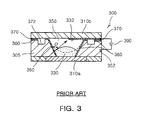
- FIGs. 2 and 3 illustrate a conventional liquid lens 300 adopting such a basic principle.
- a body 305 is made of a conductive material and has an inner space 305a in a central portion thereof.
- a transparent substrate 310a is disposed underneath the body 305.
- the inner space 305a is filled with a non-conductive fluid 330 of oil and a conductive fluid 350 of electrolyte, which both are substantially identical in density.
- a transparent cover 310b is bonded onto the body 305. Also, a light transmissible electrode 33 is disposed underneath the cover 310b.
- insulating layers 360 are formed on both inner walls of the inner space 305a to extend along an upper surface of the body 305.
- Another electrode 352 is formed on the body 305 to connect to a power voltage and a voltage is applied to the conductive fluid 350 through the electrode 332.
- a voltage is adjustably applied to the conductive fluid 350 through the electrodes 332 and 352.
- This alters an interface angle ⁇ between insulating layers 360 and the conductive fluid 350, as shown in FIG. 3 , thereby changing a shape of the interface between the conductive fluid 350 of electrolyte and the non-conductive fluid 330 of oil.
- This accordingly alters a focal length of light propagating through the interface.
- Vigorous attempts have been made to commercialize the conventional liquid lens 300, whose final product, however, was hardly reliable.
- the body 305 made of a conductive material is filled with the non-conductive fluid 330 of oil and the conductive fluid 350 of electrolyte. Then the cover 310b is capped on the body 305 by using a bonding device (not illustrated).
- the bonding device applies an ultraviolet ray curing adhesive 370 along an outer periphery of the cover 310 so that the adhesive 370 is penetrated by a capillary phenomenon and cured to bond the cover 310b to the body 305.
- the ultraviolet ray curing adhesive 370 While the ultraviolet ray curing adhesive 370 is penetrated between the cover 310b and the body by the capillary phenomenon and cured, the adhesive penetrating in an excessive amount is trapped inside adhesive blocking grooves 372 formed in the upper surface of the body and adjacent to the inner space 305a.
- the grooves 372 block the adhesive 370 from reaching the non-conductive fluid 330 and the conductive fluid 350 inside the inner space 305a, which are thus free from any effects of the adhesive 370.
- the conventional liquid lens 300 lacks reliability. That is, a bonding portion between the cover 310b and the body 305 is limited to a small area, i.e., the outer periphery of the upper surface of the body 305. This structural vulnerability degrades durability. Moreover, heat generated from curing of the ultraviolet ray curing adhesive 370 expands the non-conductive and conductive fluids 330 and 350, weakening the bonding portion between the cover 310b and the body 305.
- an image pickup apparatus including a liquid lens containing two fluids that interface at a meniscus.
- the fluids are of the same specific gravity, differ as to refractive index and are insoluable in one another. It is believed that a lens of this type may be sub-optimal as to the bonding needed to contain the fluids.
- the present invention has been made to solve the foregoing problems of the prior art.
- the present invention (as defined by claim 1) provides a liquid lens with an improved sealing structure, in which a glass cover and a body are bonded together by two types of adhesives with different compositions to greatly withstand temperature and heat impact and stay durable even in a high-temperature humid environment, thereby significantly enhancing reliability of the final product.
- An aspect of the invention is to provide a liquid lens with an improved sealing structure in which an internal fluid is minimally expanded to bond an upper cover to the body stably, thereby minimizing product defects in a manufacturing process.
- a liquid lens for adjusting a focal length by electro-wetting comprising: a body housing a non-conductive fluid and a conductive fluid therein; a transparent cover capped on the body wherein a lower portion of the transparent cover is bonded with an upper surface of the body by a first adhesive; characterised by a step formed on the upper surface of the body, wherein a second adhesive arranged to bond an outer periphery of the body to an outer periphery of the cover is applied to the outer periphery of the transparent cover on the step, wherein the step is formed on the body along the outer periphery of the transparent cover; wherein the step has a vertical edge conforming to the outer periphery of the transparent cover; and wherein the second adhesive has a different composition than the first adhesive.
- the first adhesive comprises an ultraviolet ray curing adhesive mainly composed of modified acrylate.
- the second adhesive comprises an ultraviolet ray curing adhesive added with acryl.
- FIG. 1 is a cross-sectional view illustrating a conventional liquid lens using electro-wetting
- FIG. 2 is an exploded perspective view illustrating a conventional liquid lens with only a first bonding part
- FIG. 3 is a cross-sectional view illustrating a conventional liquid lens with only a first bonding part
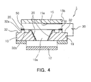
- FIG. 4 is an exploded perspective view illustrating a liquid lens with an improved sealing structure according to the invention.
- FIG. 5 is a cross-sectional view illustrating a liquid lens with an improved sealing structure according to the invention.
- the liquid lens 1 with an improved sealing structure includes a body housing a non-conductive fluid 5 and a conductive fluid 7 therein.
- the body 10 has an inner space 10a formed in a central portion thereof, and is made of a conductive material, preferably stainless material such as steel use stainless(SUS).
- a transparent substrate 12, i.e., made of a glass material is disposed underneath the body 10.
- the inner space 10a is filled with a non-conductive fluid 5 of oil and a conductive fluid 7 of electrolyte, which both are substantially identical in density. Also, a transparent cover 15, preferably made of a transparent glass, is capped on the body 10. A light transmissible electrode 15a is disposed underneath the cover 15.
- insulating layers 20 are formed on both inner walls of the inner space 10a of the body 10, extending along an upper surface of the body 10.
- An electrode 19 is formed in the body 10 to connect to a power voltage 30.
- the body 10 has a step 32 formed on the upper surface thereof along an outer periphery 15b of the cover 15.
- the step 32 has a cross-sectional shape of "L”, and has a vertical edge 32a conforming to the outer periphery 15b of the cover 15.
- the vertical edge 32a of the step 32 identical to the outer periphery 15b of the cover 15 allows stable bonding of a first adhesive 50 and a second adhesive 60, which will be explained later.
- the body 10 has an adhesive blocking groove 32a formed in the outer periphery 15b at one end thereof, adjacent to the inner space 10a. This prevents the adhesives for bonding the cover 15 and the body 10 together from reaching the non-conductive fluid 5 and the conductive fluid 7 inside the inner space 10a.
- the non-conductive fluid 5 of oil and the conductive fluid 7 of electrolyte are filled in the inner space 10a of the body.
- the cover 15 is capped on the body 10 via a bonding device (not illustrated) .
- the first adhesive 50 is applied on a bonding portion between the body 10 and the cover 15 by a dispenser and the cover 15 is capped thereon to be bonded and cured.
- the first adhesive 50 is preferably made of an ultraviolet ray curing adhesive mainly composed of modified acrylate.
- the first adhesive 50 is applied between the upper cover 15 and the body 10 and cured fast by ultraviolet ray irradiation, thereby bonding the cover 15 to the body 10 stably.
- the first adhesive 50 is made of an ultraviolet ray curing adhesive mainly composed of modified acrylate. This allows the first adhesive 50 be cured rapidly, thereby preventing the non-conductive fluid 5 and the conductive fluid 7 inside the body 10 from thermally expanding. That is, the first adhesive 50 is rapidly cured before the fluids inside the body thermally expand thereby to primarily bond the cover 15 to the body 10.
- the outer periphery 15b of the upper cover 15 is secondarily bonded by virtue of the step 32 of the body.
- the second adhesive 60 is applied along the outer periphery 15b of the cover 15 on the step 32.
- the second adhesive 60 is made of an ultraviolet ray curing adhesive added with acryl and cured by ultraviolet ray irradiation, thus assuring high reliability.
- a voltage when applied to the conductive fluid 7 through the electrodes 15a and 19, alters an interface angle ⁇ between the insulating layer 20 and the conductive fluid 7. This consequently alters a shape of the interface between the conductive fluid 7 of electrolyte and the non-conductive fluid 5 of oil, thereby changing a focal length of light propagating therethrough.
- the first adhesive 50 is made of an ultraviolet ray curing adhesive mainly composed of modified acrylate.
- the first adhesive 50 is cured very rapidly, thereby preventing the non-conductive fluid 5 and the conductive fluid 7 inside the body 10 from thermally expanding. This allows the cover 15 to be bonded to the body 10 stably.
- the second adhesive 60 is applied across a large area, i.e., along the outer periphery 15b of the cover 15 and on the step 32 of the body 10. This enables the cover 15 to be bonded solidly to the body 10.
- the cover 15 and the body 10 are attached to each other stably, thereby producing the liquid lens with a lower height.
- the liquid lens of the invention when manufactured, is strong against heat impact and perfectly sealed even in a high-temperature humid environment, thus staying durable and improved in reliability of the product significantly.
- a glass cover and a body are bonded together across a large area by two types of adhesives with different compositions. Therefore, the lens, after manufactured, is strong against temperature and heat impact, durable even in a high-temperature humid environment, thereby enhancing reliability of the final product noticeably.
- the adhesives for bonding an upper cover and the body together are cured rapidly so that non-conductive and conductive fluids inside the body are minimally expanded. This allows the cover to be bonded solidly to the body, thereby minimizing product defects that may occur during a manufacturing process.
Landscapes
- Physics & Mathematics (AREA)
- General Physics & Mathematics (AREA)
- Optics & Photonics (AREA)
- Electrochromic Elements, Electrophoresis, Or Variable Reflection Or Absorption Elements (AREA)
- Mechanical Light Control Or Optical Switches (AREA)
- Adhesives Or Adhesive Processes (AREA)
- Lens Barrels (AREA)
- Telescopes (AREA)
Claims (2)
- Flüssiglinse zum Anpassen einer Brennweite durch Elektrobenetzung wobei die Flüssiglinse Folgendes umfasst:einen Körper (10), der ein nicht leitfähiges Fluid. (5) und ein leitfähiges Fluid (7) darin aufnimmt;eine durchsichtige Abdeckung (15), die auf den Körper aufgestülpt wird, wobei ein unterer Abschnitt der durchsichtigen Abdeckung mit einer oberen Oberfläche des Körpers durch einen ernsten Klebstoff (50) verbunden ist;gekennzeichnet durch eine Stufe (32), die auf der oberen Oberfläche des Körpers gebildet ist, wobei ein zweiter Klebstoff (60), der angeordnet ist, um einen äußeren Umfang des Körpers mit einem äußeren Umfang der Abdeckung zu verbinden, auf den äußeren Umfang der durchsichtigen Abdeckung auf der Stufe aufgetragen wird, wobei die Stufe (32) auf dem Körper (10) an dem äußeren Umfang der durchsichtigen Abdeckung (15) entlang gebildet ist; wobei die Stufe (32) einen senkrechten Rand (32a) aufweist, der sich den äußeren Umfang der durchsichtigen Abdeckung (15) anpasst; und wobei der zweite Klebstoff eine andere Zusammensetzung als der erste Klebstoff aufweist.
- Flüssiglinse nach Anspruch 1, wobei der zweite Klebstoff (60) einen mit Acryl angereicherten UV-härtbaren Klebstoff umfasst.
Applications Claiming Priority (1)
| Application Number | Priority Date | Filing Date | Title |
|---|---|---|---|
| KR1020060036901A KR100771818B1 (ko) | 2006-04-24 | 2006-04-24 | 밀봉 성능이 향상된 액체 렌즈 |
Publications (2)
| Publication Number | Publication Date |
|---|---|
| EP1850153A1 EP1850153A1 (de) | 2007-10-31 |
| EP1850153B1 true EP1850153B1 (de) | 2010-10-27 |
Family
ID=38180197
Family Applications (1)
| Application Number | Title | Priority Date | Filing Date |
|---|---|---|---|
| EP07250914A Not-in-force EP1850153B1 (de) | 2006-04-24 | 2007-03-06 | Flüssiglinse mit verbesserter Versiegelungsstruktur |
Country Status (7)
| Country | Link |
|---|---|
| US (1) | US7545574B2 (de) |
| EP (1) | EP1850153B1 (de) |
| JP (1) | JP2007293283A (de) |
| KR (1) | KR100771818B1 (de) |
| CN (1) | CN100580484C (de) |
| AT (1) | ATE486293T1 (de) |
| DE (1) | DE602007010051D1 (de) |
Families Citing this family (22)
| Publication number | Priority date | Publication date | Assignee | Title |
|---|---|---|---|---|
| US20100060991A1 (en) * | 2008-09-11 | 2010-03-11 | Omnivision Technologies, Inc. | Electrically-Controlled, Variable Focal Length Liquid-Based Optical Imaging Apparatus and Method |
| US8309245B2 (en) * | 2009-06-06 | 2012-11-13 | Apple Inc. | Battery pack and connector |
| US8892238B2 (en) | 2009-10-06 | 2014-11-18 | Edward T. Sweet | Edge break details and processing |
| US20110081839A1 (en) * | 2009-10-06 | 2011-04-07 | Apple Inc. | Method and apparatus for polishing a curved edge |
| US8333862B2 (en) * | 2009-10-16 | 2012-12-18 | Apple Inc. | Self fixturing assembly techniques |
| US8199468B2 (en) * | 2009-10-16 | 2012-06-12 | Apple Inc. | Computer housing |
| US8233109B2 (en) | 2009-10-16 | 2012-07-31 | Apple Inc. | Portable computer display housing |
| US8553907B2 (en) | 2009-10-16 | 2013-10-08 | Apple Inc. | Portable computer electrical grounding and audio system architectures |
| US8854801B2 (en) * | 2009-10-16 | 2014-10-07 | Apple Inc. | Portable computer display housing |
| US8111505B2 (en) | 2009-10-16 | 2012-02-07 | Apple Inc. | Computer housing |
| US20110089792A1 (en) * | 2009-10-16 | 2011-04-21 | Apple Inc. | Portable computer housing |
| US8638549B2 (en) | 2010-08-24 | 2014-01-28 | Apple Inc. | Electronic device display module |
| US20120092774A1 (en) * | 2010-09-27 | 2012-04-19 | Pugh Randall B | Lens with multi-segmented linear meniscus wall |
| JP5516333B2 (ja) * | 2010-11-02 | 2014-06-11 | ソニー株式会社 | 光学素子および立体表示装置 |
| KR101328221B1 (ko) * | 2010-11-26 | 2013-11-14 | 삼성전기주식회사 | 압전진동자 |
| US9201452B2 (en) | 2012-02-28 | 2015-12-01 | Apple Inc. | Electronic device with illuminated logo structures |
| DE102014011474A1 (de) | 2014-07-30 | 2016-02-04 | Kienle + Spiess Gmbh | Lamellenpaket sowie Verfahren zu dessen Herstellung |
| KR102660803B1 (ko) * | 2016-09-13 | 2024-04-26 | 엘지이노텍 주식회사 | 듀얼 카메라 모듈 및 광학 장치 |
| JP7146740B2 (ja) | 2016-09-13 | 2022-10-04 | エルジー イノテック カンパニー リミテッド | デュアルカメラモジュール、光学装置、カメラモジュール及びカメラモジュールの動作方法 |
| KR20180094615A (ko) * | 2017-02-16 | 2018-08-24 | 엘지이노텍 주식회사 | 액체 렌즈 및 이를 포함하는 카메라 모듈 |
| KR102322843B1 (ko) | 2017-03-30 | 2021-11-08 | 엘지이노텍 주식회사 | 액체 렌즈를 포함하는 카메라 모듈 |
| KR101908658B1 (ko) | 2017-11-02 | 2018-12-10 | 엘지이노텍 주식회사 | 액체 렌즈를 포함하는 카메라 모듈 및 광학 기기 |
Citations (1)
| Publication number | Priority date | Publication date | Assignee | Title |
|---|---|---|---|---|
| DE102006049426A1 (de) * | 2005-11-01 | 2007-05-03 | Samsung Electro-Mechanics Co., Ltd., Suwon | Flüssigkeitszoomlinse |
Family Cites Families (13)
| Publication number | Priority date | Publication date | Assignee | Title |
|---|---|---|---|---|
| JP2732569B2 (ja) | 1987-02-23 | 1998-03-30 | オリンパス光学工業株式会社 | 液晶レンズ |
| JPH02271317A (ja) * | 1989-04-12 | 1990-11-06 | Olympus Optical Co Ltd | 液晶レンズ |
| JP4532651B2 (ja) * | 2000-03-03 | 2010-08-25 | キヤノン株式会社 | 可変焦点レンズ、光学系および撮影装置 |
| JP4521920B2 (ja) * | 2000-03-03 | 2010-08-11 | キヤノン株式会社 | 光学素子の静電容量検出装置、および静電容量検出装置を備えた光学装置 |
| JP2001249348A (ja) | 2000-03-07 | 2001-09-14 | Olympus Optical Co Ltd | 液晶レンズ |
| JP2002162506A (ja) * | 2000-11-27 | 2002-06-07 | Canon Inc | 光学素子、光学装置および撮影装置 |
| WO2004102246A1 (ja) | 2003-05-15 | 2004-11-25 | Konica Minolta Opto, Inc. | 光学系及び撮像装置 |
| JP4399202B2 (ja) * | 2003-08-20 | 2010-01-13 | 東北パイオニア株式会社 | フラットパネル表示装置の製造方法 |
| JP2007536591A (ja) * | 2004-05-07 | 2007-12-13 | コーニンクレッカ フィリップス エレクトロニクス エヌ ヴィ | エレクトロウェッティングセル及びその製造方法 |
| US20080137213A1 (en) | 2004-05-07 | 2008-06-12 | Koninklijke Philips Electronics, N.V. | Electrowetting Cell and Method for Driving it |
| FR2887637B1 (fr) | 2005-06-23 | 2008-02-22 | Varioptic Sa | Procede de fabrication d'une lentille a focale variable a electromouillage |
| JP4356681B2 (ja) * | 2005-10-21 | 2009-11-04 | セイコーエプソン株式会社 | 液晶装置の製造方法 |
| KR100847804B1 (ko) | 2005-11-15 | 2008-08-06 | (주) 비앤피 사이언스 | 액체 렌즈 및 액체 렌즈 제조 방법 |
-
2006
- 2006-04-24 KR KR1020060036901A patent/KR100771818B1/ko not_active Expired - Fee Related
-
2007
- 2007-03-05 US US11/713,609 patent/US7545574B2/en not_active Expired - Fee Related
- 2007-03-06 EP EP07250914A patent/EP1850153B1/de not_active Not-in-force
- 2007-03-06 DE DE602007010051T patent/DE602007010051D1/de active Active
- 2007-03-06 AT AT07250914T patent/ATE486293T1/de not_active IP Right Cessation
- 2007-03-07 JP JP2007057047A patent/JP2007293283A/ja active Pending
- 2007-03-08 CN CN200710086069A patent/CN100580484C/zh not_active Expired - Fee Related
Patent Citations (1)
| Publication number | Priority date | Publication date | Assignee | Title |
|---|---|---|---|---|
| DE102006049426A1 (de) * | 2005-11-01 | 2007-05-03 | Samsung Electro-Mechanics Co., Ltd., Suwon | Flüssigkeitszoomlinse |
Also Published As
| Publication number | Publication date |
|---|---|
| KR100771818B1 (ko) | 2007-10-30 |
| ATE486293T1 (de) | 2010-11-15 |
| DE602007010051D1 (de) | 2010-12-09 |
| CN101063723A (zh) | 2007-10-31 |
| US7545574B2 (en) | 2009-06-09 |
| US20070247723A1 (en) | 2007-10-25 |
| CN100580484C (zh) | 2010-01-13 |
| EP1850153A1 (de) | 2007-10-31 |
| JP2007293283A (ja) | 2007-11-08 |
| KR20070104805A (ko) | 2007-10-29 |
Similar Documents
| Publication | Publication Date | Title |
|---|---|---|
| EP1850153A1 (de) | Flüssiglinse mit verbesserter Versiegelungsstruktur | |
| CN101858996B (zh) | 液体透镜装置及其制造方法 | |
| TWI413806B (zh) | 可變焦距透鏡 | |
| US20070247724A1 (en) | Liquid lens with curved contact surface | |
| US20100232028A1 (en) | Optical element and lens array | |
| EP2105768B1 (de) | Flüssige optische Linse mit einem elektrostriktiven Polymer Antrieb | |
| US8111464B2 (en) | Optical lens and manufacturing method thereof | |
| US8238033B2 (en) | Liquid lens device and manufacturing method therefor | |
| TW200813487A (en) | Liquid lens with four liquids | |
| US20120099030A1 (en) | Cholesteric liquid crystal writing tablet with spacer controlled sensitivity | |
| US7909974B2 (en) | Layer composition of an electrowetting system | |
| US9453997B2 (en) | Electrowetting display device | |
| CN103424949B (zh) | 电泳器件及其制造方法、电泳显示装置、和电子装置 | |
| CN100523877C (zh) | 变焦距透镜 | |
| JP2009518676A (ja) | 流体フォーカスレンズにおける溶液流の防止 | |
| US7782541B2 (en) | Variable focus lens having a plurality of protrusions at one end of fluid chamber | |
| US20060256448A1 (en) | Variable-focus lens and fabrication method thereof | |
| JP2009276450A (ja) | 光学素子及びその製造方法 | |
| US20240045300A1 (en) | Touch display device and manufacturing method thereof | |
| JP2003302502A (ja) | 光学素子 | |
| KR20070008169A (ko) | 액체 렌즈 | |
| KR100636433B1 (ko) | 렌즈 소자 | |
| KR20060111756A (ko) | 액체렌즈 및 액체렌즈의 제작방법 | |
| JP2018045033A (ja) | 電気泳動表示装置、電気泳動表示装置の製造方法および電子機器 | |
| WO2009100584A1 (en) | Liquid optical deflector and method for fabricating the same |
Legal Events
| Date | Code | Title | Description |
|---|---|---|---|
| PUAI | Public reference made under article 153(3) epc to a published international application that has entered the european phase |
Free format text: ORIGINAL CODE: 0009012 |
|
| AK | Designated contracting states |
Kind code of ref document: A1 Designated state(s): AT BE BG CH CY CZ DE DK EE ES FI FR GB GR HU IE IS IT LI LT LU LV MC MT NL PL PT RO SE SI SK TR |
|
| AX | Request for extension of the european patent |
Extension state: AL BA HR MK YU |
|
| 17P | Request for examination filed |
Effective date: 20071102 |
|
| 17Q | First examination report despatched |
Effective date: 20071213 |
|
| AKX | Designation fees paid |
Designated state(s): AT BE BG CH CY CZ DE DK EE ES FI FR GB GR HU IE IS IT LI LT LU LV MC MT NL PL PT RO SE SI SK TR |
|
| GRAP | Despatch of communication of intention to grant a patent |
Free format text: ORIGINAL CODE: EPIDOSNIGR1 |
|
| GRAS | Grant fee paid |
Free format text: ORIGINAL CODE: EPIDOSNIGR3 |
|
| GRAA | (expected) grant |
Free format text: ORIGINAL CODE: 0009210 |
|
| AK | Designated contracting states |
Kind code of ref document: B1 Designated state(s): AT BE BG CH CY CZ DE DK EE ES FI FR GB GR HU IE IS IT LI LT LU LV MC MT NL PL PT RO SE SI SK TR |
|
| REG | Reference to a national code |
Ref country code: GB Ref legal event code: FG4D |
|
| REG | Reference to a national code |
Ref country code: CH Ref legal event code: EP |
|
| REG | Reference to a national code |
Ref country code: IE Ref legal event code: FG4D |
|
| REF | Corresponds to: |
Ref document number: 602007010051 Country of ref document: DE Date of ref document: 20101209 Kind code of ref document: P |
|
| REG | Reference to a national code |
Ref country code: NL Ref legal event code: VDEP Effective date: 20101027 |
|
| LTIE | Lt: invalidation of european patent or patent extension |
Effective date: 20101027 |
|
| PG25 | Lapsed in a contracting state [announced via postgrant information from national office to epo] |
Ref country code: LT Free format text: LAPSE BECAUSE OF FAILURE TO SUBMIT A TRANSLATION OF THE DESCRIPTION OR TO PAY THE FEE WITHIN THE PRESCRIBED TIME-LIMIT Effective date: 20101027 |
|
| PG25 | Lapsed in a contracting state [announced via postgrant information from national office to epo] |
Ref country code: PT Free format text: LAPSE BECAUSE OF FAILURE TO SUBMIT A TRANSLATION OF THE DESCRIPTION OR TO PAY THE FEE WITHIN THE PRESCRIBED TIME-LIMIT Effective date: 20110228 Ref country code: NL Free format text: LAPSE BECAUSE OF FAILURE TO SUBMIT A TRANSLATION OF THE DESCRIPTION OR TO PAY THE FEE WITHIN THE PRESCRIBED TIME-LIMIT Effective date: 20101027 Ref country code: FI Free format text: LAPSE BECAUSE OF FAILURE TO SUBMIT A TRANSLATION OF THE DESCRIPTION OR TO PAY THE FEE WITHIN THE PRESCRIBED TIME-LIMIT Effective date: 20101027 Ref country code: IS Free format text: LAPSE BECAUSE OF FAILURE TO SUBMIT A TRANSLATION OF THE DESCRIPTION OR TO PAY THE FEE WITHIN THE PRESCRIBED TIME-LIMIT Effective date: 20110227 Ref country code: SE Free format text: LAPSE BECAUSE OF FAILURE TO SUBMIT A TRANSLATION OF THE DESCRIPTION OR TO PAY THE FEE WITHIN THE PRESCRIBED TIME-LIMIT Effective date: 20101027 Ref country code: SI Free format text: LAPSE BECAUSE OF FAILURE TO SUBMIT A TRANSLATION OF THE DESCRIPTION OR TO PAY THE FEE WITHIN THE PRESCRIBED TIME-LIMIT Effective date: 20101027 Ref country code: AT Free format text: LAPSE BECAUSE OF FAILURE TO SUBMIT A TRANSLATION OF THE DESCRIPTION OR TO PAY THE FEE WITHIN THE PRESCRIBED TIME-LIMIT Effective date: 20101027 Ref country code: LV Free format text: LAPSE BECAUSE OF FAILURE TO SUBMIT A TRANSLATION OF THE DESCRIPTION OR TO PAY THE FEE WITHIN THE PRESCRIBED TIME-LIMIT Effective date: 20101027 Ref country code: BG Free format text: LAPSE BECAUSE OF FAILURE TO SUBMIT A TRANSLATION OF THE DESCRIPTION OR TO PAY THE FEE WITHIN THE PRESCRIBED TIME-LIMIT Effective date: 20110127 |
|
| PG25 | Lapsed in a contracting state [announced via postgrant information from national office to epo] |
Ref country code: BE Free format text: LAPSE BECAUSE OF FAILURE TO SUBMIT A TRANSLATION OF THE DESCRIPTION OR TO PAY THE FEE WITHIN THE PRESCRIBED TIME-LIMIT Effective date: 20101027 Ref country code: GR Free format text: LAPSE BECAUSE OF FAILURE TO SUBMIT A TRANSLATION OF THE DESCRIPTION OR TO PAY THE FEE WITHIN THE PRESCRIBED TIME-LIMIT Effective date: 20110128 |
|
| PG25 | Lapsed in a contracting state [announced via postgrant information from national office to epo] |
Ref country code: ES Free format text: LAPSE BECAUSE OF FAILURE TO SUBMIT A TRANSLATION OF THE DESCRIPTION OR TO PAY THE FEE WITHIN THE PRESCRIBED TIME-LIMIT Effective date: 20110207 Ref country code: CZ Free format text: LAPSE BECAUSE OF FAILURE TO SUBMIT A TRANSLATION OF THE DESCRIPTION OR TO PAY THE FEE WITHIN THE PRESCRIBED TIME-LIMIT Effective date: 20101027 Ref country code: EE Free format text: LAPSE BECAUSE OF FAILURE TO SUBMIT A TRANSLATION OF THE DESCRIPTION OR TO PAY THE FEE WITHIN THE PRESCRIBED TIME-LIMIT Effective date: 20101027 |
|
| PG25 | Lapsed in a contracting state [announced via postgrant information from national office to epo] |
Ref country code: DK Free format text: LAPSE BECAUSE OF FAILURE TO SUBMIT A TRANSLATION OF THE DESCRIPTION OR TO PAY THE FEE WITHIN THE PRESCRIBED TIME-LIMIT Effective date: 20101027 Ref country code: SK Free format text: LAPSE BECAUSE OF FAILURE TO SUBMIT A TRANSLATION OF THE DESCRIPTION OR TO PAY THE FEE WITHIN THE PRESCRIBED TIME-LIMIT Effective date: 20101027 Ref country code: PL Free format text: LAPSE BECAUSE OF FAILURE TO SUBMIT A TRANSLATION OF THE DESCRIPTION OR TO PAY THE FEE WITHIN THE PRESCRIBED TIME-LIMIT Effective date: 20101027 Ref country code: RO Free format text: LAPSE BECAUSE OF FAILURE TO SUBMIT A TRANSLATION OF THE DESCRIPTION OR TO PAY THE FEE WITHIN THE PRESCRIBED TIME-LIMIT Effective date: 20101027 |
|
| PLBE | No opposition filed within time limit |
Free format text: ORIGINAL CODE: 0009261 |
|
| STAA | Information on the status of an ep patent application or granted ep patent |
Free format text: STATUS: NO OPPOSITION FILED WITHIN TIME LIMIT |
|
| 26N | No opposition filed |
Effective date: 20110728 |
|
| PG25 | Lapsed in a contracting state [announced via postgrant information from national office to epo] |
Ref country code: MC Free format text: LAPSE BECAUSE OF NON-PAYMENT OF DUE FEES Effective date: 20110331 |
|
| REG | Reference to a national code |
Ref country code: CH Ref legal event code: PL |
|
| GBPC | Gb: european patent ceased through non-payment of renewal fee |
Effective date: 20110306 |
|
| REG | Reference to a national code |
Ref country code: DE Ref legal event code: R097 Ref document number: 602007010051 Country of ref document: DE Effective date: 20110728 |
|
| REG | Reference to a national code |
Ref country code: FR Ref legal event code: ST Effective date: 20111130 |
|
| PG25 | Lapsed in a contracting state [announced via postgrant information from national office to epo] |
Ref country code: MT Free format text: LAPSE BECAUSE OF FAILURE TO SUBMIT A TRANSLATION OF THE DESCRIPTION OR TO PAY THE FEE WITHIN THE PRESCRIBED TIME-LIMIT Effective date: 20101027 Ref country code: IT Free format text: LAPSE BECAUSE OF FAILURE TO SUBMIT A TRANSLATION OF THE DESCRIPTION OR TO PAY THE FEE WITHIN THE PRESCRIBED TIME-LIMIT Effective date: 20101027 |
|
| REG | Reference to a national code |
Ref country code: IE Ref legal event code: MM4A |
|
| PG25 | Lapsed in a contracting state [announced via postgrant information from national office to epo] |
Ref country code: LI Free format text: LAPSE BECAUSE OF NON-PAYMENT OF DUE FEES Effective date: 20110331 Ref country code: FR Free format text: LAPSE BECAUSE OF NON-PAYMENT OF DUE FEES Effective date: 20110331 Ref country code: DE Free format text: LAPSE BECAUSE OF NON-PAYMENT OF DUE FEES Effective date: 20111001 Ref country code: CH Free format text: LAPSE BECAUSE OF NON-PAYMENT OF DUE FEES Effective date: 20110331 Ref country code: IE Free format text: LAPSE BECAUSE OF NON-PAYMENT OF DUE FEES Effective date: 20110306 |
|
| REG | Reference to a national code |
Ref country code: DE Ref legal event code: R119 Ref document number: 602007010051 Country of ref document: DE Effective date: 20111001 |
|
| PG25 | Lapsed in a contracting state [announced via postgrant information from national office to epo] |
Ref country code: GB Free format text: LAPSE BECAUSE OF NON-PAYMENT OF DUE FEES Effective date: 20110306 |
|
| PG25 | Lapsed in a contracting state [announced via postgrant information from national office to epo] |
Ref country code: LU Free format text: LAPSE BECAUSE OF NON-PAYMENT OF DUE FEES Effective date: 20110306 Ref country code: CY Free format text: LAPSE BECAUSE OF FAILURE TO SUBMIT A TRANSLATION OF THE DESCRIPTION OR TO PAY THE FEE WITHIN THE PRESCRIBED TIME-LIMIT Effective date: 20101027 |
|
| PG25 | Lapsed in a contracting state [announced via postgrant information from national office to epo] |
Ref country code: TR Free format text: LAPSE BECAUSE OF FAILURE TO SUBMIT A TRANSLATION OF THE DESCRIPTION OR TO PAY THE FEE WITHIN THE PRESCRIBED TIME-LIMIT Effective date: 20101027 |
|
| PG25 | Lapsed in a contracting state [announced via postgrant information from national office to epo] |
Ref country code: HU Free format text: LAPSE BECAUSE OF FAILURE TO SUBMIT A TRANSLATION OF THE DESCRIPTION OR TO PAY THE FEE WITHIN THE PRESCRIBED TIME-LIMIT Effective date: 20101027 |