EP1850305A2 - Dispositif d'affichage destiné à la représentation par saisie tactile d'éléments d'information et système d'affichage doté d'un tel dispositif d'affichage - Google Patents
Dispositif d'affichage destiné à la représentation par saisie tactile d'éléments d'information et système d'affichage doté d'un tel dispositif d'affichage Download PDFInfo
- Publication number
- EP1850305A2 EP1850305A2 EP07008182A EP07008182A EP1850305A2 EP 1850305 A2 EP1850305 A2 EP 1850305A2 EP 07008182 A EP07008182 A EP 07008182A EP 07008182 A EP07008182 A EP 07008182A EP 1850305 A2 EP1850305 A2 EP 1850305A2
- Authority
- EP
- European Patent Office
- Prior art keywords
- display
- display device
- area
- elements
- touch surface
- Prior art date
- Legal status (The legal status is an assumption and is not a legal conclusion. Google has not performed a legal analysis and makes no representation as to the accuracy of the status listed.)
- Withdrawn
Links
- 239000000523 sample Substances 0.000 claims abstract description 8
- 239000011159 matrix material Substances 0.000 claims description 11
- 239000003990 capacitor Substances 0.000 claims description 9
- 238000001514 detection method Methods 0.000 claims description 3
- 238000011156 evaluation Methods 0.000 claims description 3
- 238000004590 computer program Methods 0.000 abstract description 16
- 230000001771 impaired effect Effects 0.000 abstract description 8
- 230000003993 interaction Effects 0.000 abstract description 6
- 230000006870 function Effects 0.000 description 5
- 239000010453 quartz Substances 0.000 description 5
- VYPSYNLAJGMNEJ-UHFFFAOYSA-N silicon dioxide Inorganic materials O=[Si]=O VYPSYNLAJGMNEJ-UHFFFAOYSA-N 0.000 description 5
- 230000008859 change Effects 0.000 description 4
- 239000013078 crystal Substances 0.000 description 3
- 230000002349 favourable effect Effects 0.000 description 3
- 238000011161 development Methods 0.000 description 2
- 230000018109 developmental process Effects 0.000 description 2
- 230000008901 benefit Effects 0.000 description 1
- 238000004364 calculation method Methods 0.000 description 1
- 238000004891 communication Methods 0.000 description 1
- 230000000295 complement effect Effects 0.000 description 1
- 239000004020 conductor Substances 0.000 description 1
- 230000000994 depressogenic effect Effects 0.000 description 1
- 238000010586 diagram Methods 0.000 description 1
- 230000005484 gravity Effects 0.000 description 1
- 238000000034 method Methods 0.000 description 1
- 230000004048 modification Effects 0.000 description 1
- 238000012986 modification Methods 0.000 description 1
- 230000010355 oscillation Effects 0.000 description 1
- 230000008447 perception Effects 0.000 description 1
- 230000008569 process Effects 0.000 description 1
- 238000012545 processing Methods 0.000 description 1
- 230000004044 response Effects 0.000 description 1
- 230000035945 sensitivity Effects 0.000 description 1
- 239000000725 suspension Substances 0.000 description 1
- 230000001360 synchronised effect Effects 0.000 description 1
- 238000013519 translation Methods 0.000 description 1
- 230000000007 visual effect Effects 0.000 description 1
Images




Classifications
-
- G—PHYSICS
- G09—EDUCATION; CRYPTOGRAPHY; DISPLAY; ADVERTISING; SEALS
- G09B—EDUCATIONAL OR DEMONSTRATION APPLIANCES; APPLIANCES FOR TEACHING, OR COMMUNICATING WITH, THE BLIND, DEAF OR MUTE; MODELS; PLANETARIA; GLOBES; MAPS; DIAGRAMS
- G09B21/00—Teaching, or communicating with, the blind, deaf or mute
- G09B21/001—Teaching or communicating with blind persons
- G09B21/003—Teaching or communicating with blind persons using tactile presentation of the information, e.g. Braille displays
Definitions
- the invention relates to a display system with such a display device.
- display elements are understood to mean all representations which can be visually detected by normal vision users, for example on a computer screen.
- These display elements can thus be pure picture elements (graphics), but also drawing elements (characters, symbols or the like).
- tactile display devices For blind and partially sighted persons, tactile display devices mentioned at the beginning are known, which information to be output by a computer in braille characters implement by using a stylus individual display pins are driven by actuators according to the output of the computer.
- Such tactile display devices are thus capable of displaying alpha-numeric information and graphics.
- the display elements displayed on the display immediately removable information is limited to the tactile form of the display element.
- the blind or visually impaired user must interpret at each tactile pen to what kind of information the fingered pen belongs, so if the fingered pen, for example, part of a Braille symbol, a graphical representation of unknown scale, a black letter, a control element or like that.
- the object of the invention is to provide a tactile display device and a display system of the type mentioned, which are adapted to convey a higher information content on a tactile detectable display element, and in which this higher information content relatively easy from a blind or visually impaired User can be detected and processed.
- surface regions are to be understood as regions of the tactile surface in each of which different information can be detected tactilely Display element can be displayed.
- the shape of a circle displayed on a monitor of a computer in a first surface area of the touch surface is displayed in a scale adapted to the dimension of the first surface area.
- the second area e.g. displayed in user-learnable symbology that the circle in the first area is a graphic.
- the user upon sensing the circle in the first area, the user can instantly detect, based on the tactile display in the second area, that the circle is a graphic and not an operating program of the computer program or a character or part thereof.
- the display in the first area area removable information about the display element shown there is the shape of the display element per se.
- the information on the display element can be read out from the display in the second surface area that this is a graphic.
- the first surface area is a display area in which at least 180 scanning elements are provided, so that the tactile detectable shape of at least one display element can be displayed in it.
- the second Surface area is a control area, in which at least 100 sensing elements are provided so that at least one property of the displayed in the display area of the display element can be displayed in it.
- the display device has a sufficient size to display both the display element per se and its property (graphics, characters, operating icon or the like and the position of the display element on the touch surface).
- An advantageously dimensioned tactile surface is available if a total of at least 9,000 probe elements are provided, wherein a total of 9,000 probe elements can be arranged in a matrix of 75 rows and 120 columns.
- the display area can have such dimensions that display elements can be displayed there on a scale which facilitates the tactile perception of the user.
- sensor means are provided which cooperate with the fingers of a user. This allows interaction of the user with the display device or the data flow underlying the display on the display device, for example that of an executed computer program.
- the sensor means comprise at least one electrode which forms part of a capacitor which is connected to a capacitance measuring device.
- a sensor is relatively inexpensive to implement and has sufficient sensitivity.
- the position of the respective surface regions on the touch surface can be predefined while simultaneously responding to a predetermined number of sensor means depending on the position of the responsive sensor means on the display device.
- the user to align the various areas of the area according to his personal preferences on the display device. For example, the number of sensor means that must respond depends on which area they occupy together. This area may in turn correspond approximately to the area of the handball of a user.
- the position of the respective surface areas on the touch surface can be predetermined when a predetermined number of sensor means simultaneously respond over a predetermined time depending on the position of the responsive sensor means on the display device.
- the predetermined number of sensor means must respond over a predetermined period of time, it is ensured that an area does not lead to a change in position of a surface area due to an unintentional momentary suspension, for example, of a handball on the touch surface or several sensor means.
- the feeler elements can be moved by means of a servomotor between their over the tactile surface of the housing protruding Tast ein and their retracted into the clear contour of the tactile rest position.
- the above object is achieved in that a communicating with the display device processor unit is provided.
- the processor unit is programmed to evaluate a data flow and from there control signals for the control means for the control area of the display device on the one hand and for the control means for the display area of the display device calculated on the other hand.
- a data flow is evaluated in such a way that the processor unit calculates what should be displayed in the first area area and what in the second area area.
- the processor unit is programmed in such a way that it converts output signals received from the display device into control data for the data flow.
- the processor unit can intervene in a data flow due to output signals received by the display device. This can be done, for example, such that operating icons displayed on the display device are actuated via the display device, namely by triggering the sensor means of the display device.
- the evaluation of the data flow comprises the detection of at least one property of a display element.
- This property may be the shape of the display element, the type of display element and / or the position of the display element act on the touch surface.
- the shape of the display element here is to be understood not only as the outer contour, but rather as the flat shape in which the display element is displayed on the display device.
- the type of display element relates to the property to be determined, whether the display element is a picture element (graphic) or a drawing element (character, operating icon or the like).
- the processor unit controls the control of the display device such that the shape of a display element in the first surface area of the display device and the type of display element and / or its position on the touch surface in the second area of the display device is displayed.
- FIG. 1 shows a section of a tactile display panel 10 with a frame 12 in a plan view.
- the frame 12 surrounds display units 14 which are arranged in a matrix.
- Each of the display units 14 includes two columns 16, 18 of five indicator pins 20 each.
- the indicator pins 20 are displaceable in a direction perpendicular to the surface of a sensing surface 22, so as to represent a tactile image of a computer output, such as graphical display elements, Braille characters or the like.
- Each of the display units 14 has a cover plate 24, which has two rows of five guide holes 26 for each end of a display pen 20.
- the cover plate 24 is provided with an electrode generally designated 28, which serves as a capacitor electrode and forms a capacitor together with a user's finger and ground.
- the electrode 28 comprises the guide holes 26 surrounding meandering conductor tracks 30. The operation of the cover plate 24 with the electrode 28 will be explained in more detail below.
- a middle housing plate 32 which has guide bores 34 which represent an aligned continuation of the guide bores 26 of the cover plate 24.
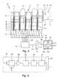
- the indicator pins 20 are connected via rod-shaped drive parts 36 with schematically indicated in Figure 3 servomotors 38, which sit firmly in the guide holes 34 of the middle housing plate 32 and have a complementary to the dimensions of the guide holes 34 housing.
- the servo motors 38 may be electromagnetic servo motors, servomotors operating according to the plunger coil principle, linear synchronous motors, combinations of a small electric motor and a rack and pinion drive or the like, or even act on fluidic servomotors.
- the servo motors 38 each have a terminal 40 which is connected via a line 42 to a controller 44.
- the power supply of the servomotors 38 is carried out in a conventional manner and is not shown for clarity.
- a bottom plate 46 is mounted, through which the servomotors 38 are supported.
- each a quartz crystal 48 is inserted, which is connected via a line 50 to the controller 44, whereby the quartz oscillator 48 is acted upon by AC voltage.
- This quartz crystal system is tuned so that the quartz oscillator 48 then vibrates at a frequency of about 1 Hz.
- the lines 50 pass through the servomotors 38 or past them and are variable in their length, which is indicated in Figure 3 by a "folded" section 52.
- the lead 50 may be carried along with a respective indicator pin 20 when extended beyond the touch surface 22.
- each cover plate 24 is connected via a line 54 to a respective circuit 56, which can be seen in detail in FIG. 4; the electrode 28 and the circuit 56 together form a sensor 28, 56.
- a comparator 58 is provided according to FIG. This can compare or measure the capacitances of the capacitors connected to its two inputs in any known manner, e.g. Example by comparing the oscillation frequencies of resonant circuits, which contain the capacitor C 1 and the capacitor C 2 as a frequency-determining element.
- the output signal of the comparator 58 can thus detect whether a user's finger is on the cover plate 24 or not.
- each display unit 14 has a cover plate 24 with only a single guide bore 26, so that it can be exactly determined over which indicator pin 20 is the user's finger.
- the output of the comparator 58 is applied to a data bus 68 via an amplifier 60, a sample / hold circuit 62, an analog-to-digital converter 64, and a logic interface 66.
- Another data bus 72 communicates with the controller 44 via a line 70.
- FIGS. 5 to 7 each show a tactile display device 10 in which 36 display units 14 are arranged in a 3 ⁇ 12 matrix. This means that there are 360 indicator pins 20 in a 15x24 matrix.
- a total of 9000 indicator pins 20 are arranged in a matrix of 120 columns and 75 rows at a pitch of about 2.5 mm. This results in approximately the area of a DIN A4 sheet.
- Black filled indicator pins 20 mean that they are brought by means of the servomotors 28 in a projecting beyond the touch surface 22 tactile position.
- the display pins 20 shown as white circles are, however, in their retracted into the light contour of the touch surface 22 rest position.
- the touch surface is 22 the tactile display panel 10 divided into two areas.
- this is a control area 74, which is delimited by the display pins a5 to j5 in line 5 and the display pins k5 to k15 in column k and a part of the frame 12.
- the control area 74 thus comprises 100 display pins 20 in a 10x10 matrix.
- the display area 76 thus comprises 180 display pins 20 in a 12x15 matrix.
- the display area 76 serves to display there usually display elements shown on a display monitor of a computer, such as graphics and / or., In the form of tactile for the user detectable information by corresponding display pins 20 by means of the controller 44 and the Actuators 38 are controlled, so that these display pins reproduce 20 line or flat display elements.
- a house is schematically illustrated by way of example in the lower area of the display area 76 in FIG. 5, whereas Braille characters are shown in the upper area of the display area 76.
- the blind or visually impaired user can indeed sense the individual display pins 20 protruding beyond the touch surface 22 in the display area 76.
- an assignment as to whether a particular display pen 20 is the part of a character or a graphic is not immediately apparent to him.
- the control area 74 is provided.
- two symbols are shown in the upper area of the control area 74 by way of example with the display pens a6 and a8 or c6, d6 and d8, which are to contain the required information.
- the symbol composed of the pins a6 and a8 means, for example, that characters are to be found in the upper area of the display area, whereas the symbol composed of the display pins c6, d6 and d8 includes a single associated graphic displayed in the lower area of the display area 76 is.
- control area 74 and the display area 76 can be arranged in different positions on the touch surface 22 of the tactile display panel 10. This is shown by way of example in FIG. 6, in which the control area 74 and the display area 76 are interchanged with respect to FIG.
- the user should expediently feel the display area 76 with his right hand and the control area 74 with his left hand. In Figure 6, this would be the reverse.
- the tactile display device 10 can thus be adapted to the personal preferences of the user, depending for example on whether the user is a right-handed or a left-handed person.
- the tactile display panel 10 is in the Able to detect where the user's hand, which should touch the control area 74, hereinafter called the control hand, is located. For this purpose, it is determined whether a plurality of contiguous surface-forming electrodes 28 at the respective comparator circuit 56 simultaneously produce an output signal. This can take place, for example, in that the user rests with the palm of his control hand on a larger area of the touch surface 22, for example on the surface 78 indicated in FIG.
- the output signals generated by a plurality of sensors 28, 56 must be maintained for a predetermined period of time, so that a position change corresponding to the position of the responsive sensors 28, 56 takes place.
- the controller may shift the control area 74 towards that in Figure 5 towards the line 1 so that the control area 74 is above the area 78 or handball of the user's control hand.
- control area 74 and the display area 76 may also be specified by the user according to his personal needs or preferences.
- the controller may include a corresponding adjustment. On the other hand, this can also be done via an appropriate software, which will be explained in more detail below.
- the tactile display panel 10 communicates via the interfaces 68 and 72 with the processor 80 of a computer 82. 72 with a processor 80 of a computer 82 in conjunction.
- This can be a conventional computer 82, which in turn communicates with a visual monitor 84 and an input field 86.
- the processor 80 may generate, via suitable software, a true-to-scale translation of the image displayed on the monitor 84 in the display area 76 of the tactile display panel 10, as appropriate to the dimension of the touch surface 22.
- the processor 80 calculates control signals for the controller 44 based on the data available to it for generating the image displayed on the monitor 84 and transmits these to the controller 44 via the data bus 72.
- the individual display elements shown on the monitor 84 are first internally converted into black and white line or point drawings whose contour or shape is a meaningful reproduction of the display elements to be recognized on the monitor 84 and which can be represented by the tactile display panel 10.
- the processor 80 determines which type the analyzed display element is, whether it is a picture element (graphic), a drawing element (characters, symbols or the like) or a control element (icon).
- the data of the computer program on the basis of which the display element "house” is generated on the monitor 84 in FIG. 8, is therefore processed by the processor 80 and assigned to a graphic.
- the processor 82 generates corresponding control signals and transmits them to the controller 44, it being provided that operating icons of the executed computer program in the control area 74, other display elements but in the display area 76 are shown.
- the controller 44 controls the corresponding actuators 38 based on the control signals generated by the processor 80, whereby the respective display pins 20 in the display area 76 of the touch surface 22 together form the image on the touch panel 22 to be seen on the display monitor 84 as a tactile detectable representation.
- the processor 80 of the calculator 82 calculates control signals for the control area 74 with respect to the display elements which do not represent an operating icon.
- the processor 80 has already determined what type of particular display element is on the display monitor 84, ie whether it is a display element Character, graphic, control, or the like.
- the associated display element is positioned in each case on the touch surface 22.
- the processor 80 transmits corresponding control signals via the data bus 72 to the controller 44, whereby predetermined Symbols are generated in the control area 74.
- the symbology to be used for the control area 74 is arbitrary, so that the user can either learn given symbols, or can himself define symbols representing certain information by programming the processor 80 accordingly.
- control area 74 and the display area 76 are controlled by separate control means, which form the control 44.
- the processor 80 evaluates the data flow of the executed computer program and calculates therefrom control signals for both the control means for the control area 74 and for the control means for the display area 76.
- the processor 80 of the computer 82 communicates with each of the comparator circuits 56 via the interface 68.
- the output signal generated by a comparator circuit 56 is received by the processor 80 and processed.
- the processor 80 may detect from the outputs of the comparator circuits 56 that the control area 74 within the touchpad 22 is to be shifted when a plurality of coalescing area-forming electrodes 28 simultaneously generate a signal or provide a sensor output for a longer period of time as a given input time (Click time).
- the response of the corresponding electrode (s) 28 When the user presses this operating icon, the response of the corresponding electrode (s) 28 generates an output signal from which the processor 80 can detect that the user wishes to switch to bold mode. The processor 80 then converts this information into corresponding control data for the word processing program, so that it changes to the bold mode.
- the output signals of the respective comparator circuits 56 must be present over a certain period of time in order to be recognized as a command signal.
- This principle is applicable to suitable software for communication of the processor 80 with the display panel 10 in a variety of different operation icons, be it part of the running computer program or specially designed for the operation of the display panel 10 operating icons.
- the type of computer program that the user wants to work with such as a word processor or a drawing program is not limited.
- the above-mentioned keypad 88 is connected via a cable 90 to the data bus 72 of the controller 44. It has four keys 920, 92U, 92R, and 92L that correspond to the "cursor up,” “cursor down, cursor right,” and “cursor left” cursor keys provided on a standard computer keyboard.
- an elevation 94 Between the perimeter of the keypad 88 and the button 920 is provided an elevation 94, whereby a blind or visually impaired user can feel, in which the key 92 is the key 920, so "cursor up", so To be able to assign the remaining keys 92.
- the position of the cursor 96 appearing on the monitor 84 is displayed on the keypad 22 by means of two vibrating indicator pins 20, designated by reference numerals 20A and 20B in FIG.
- the indicator pins 20A and 20B are caused to vibrate by means of the quartz crystal 48 by being given AC voltage therefrom by the controller 44.
- the processor 80 determines the position of the cursor 96 on the monitor 84 and generates a corresponding control signal, which is transmitted via the data bus 72 to the controller 44.
- the user If the user now wants to change the position of the cursor 96, he presses the button 920, 92U, 92R or 92L. This is transmitted via the data bus 72 to the processor 80, which moves the cursor 48 according to the depressed key 92, simultaneously calculates a new control signal and sends it to the controller 44, so that the vibrating indicator pins 20A and 20B change their position on the touch surface 22, which then corresponds to the position of the cursor 96 on the monitor 84.
- an external cursor keypad 88 has the advantage that the frequently required functions are always the same and need not be realized by expensive display units, which also take up more space. In principle, however, the cursor control can also be placed in the control area 74.
- control area 74 and the display area 76 thus allow the user to interact with the executed computer program.
- the user via the actuation of a corresponding symbol within the control area 74, can transmit the command to the computer 82 or the processor 80 that an input is now to be made.
- the display area 76 e.g. the alphabet is displayed in Braille characters, which the user can specifically capture and operate.
- the processor 80 evaluates the output signal received from the respective comparator circuit 56 and converts it into corresponding input data.
- the user By pressing another corresponding icon in the control area 74, the user indicates after his entry that it has ended.
- the display in the display area 76 then changes again from the representation of the alphabet to the playback of the image on the monitor 84, which now additionally includes the input of the user.
- the corresponding sensor 28, 56 Upon depression of a symbol in the control area 74, as indicated, the corresponding sensor 28, 56 generates an output signal which is received by the processor 80.
- the processor 80 converts this output signal into corresponding control data for the data flow of the computer program.
- control area 74 and the display area 76 serve to capture information and interaction.
- control and “representation” selected here for identifying the surface regions 74 and 76 are intended to indicate only the functional center of gravity of the respective surface region 74 or 76.
- the keypad 88 movably connected to the display device 10 via the cable 90 allows the user to freely position the keypad 88.
- the keypad 88 may also be provided connected to the frame 12 of the display device 10, or its function may be fulfilled by the cursor keys provided on a standard computer keyboard.
- the keys 92 of the keypad 88 may also perform functions other than the cursor function described herein. In principle, all types of function keys are conceivable.
- the keypad 88 can also be dispensed with and the control of, for example, the cursor, can be effected solely via corresponding symbols within the control field.
Landscapes
- Engineering & Computer Science (AREA)
- Health & Medical Sciences (AREA)
- Audiology, Speech & Language Pathology (AREA)
- General Health & Medical Sciences (AREA)
- Business, Economics & Management (AREA)
- Physics & Mathematics (AREA)
- Educational Administration (AREA)
- Educational Technology (AREA)
- General Physics & Mathematics (AREA)
- Theoretical Computer Science (AREA)
- User Interface Of Digital Computer (AREA)
- Devices For Indicating Variable Information By Combining Individual Elements (AREA)
Applications Claiming Priority (1)
| Application Number | Priority Date | Filing Date | Title |
|---|---|---|---|
| DE200610020568 DE102006020568A1 (de) | 2006-04-29 | 2006-04-29 | Anzeigevorrichtung zur taktil erfassbaren Darstellung von Anzeigeelementen sowie Anzeigesystem mit einer solchen Anzeigevorrichtung |
Publications (2)
| Publication Number | Publication Date |
|---|---|
| EP1850305A2 true EP1850305A2 (fr) | 2007-10-31 |
| EP1850305A3 EP1850305A3 (fr) | 2011-03-16 |
Family
ID=38353334
Family Applications (1)
| Application Number | Title | Priority Date | Filing Date |
|---|---|---|---|
| EP07008182A Withdrawn EP1850305A3 (fr) | 2006-04-29 | 2007-04-23 | Dispositif d'affichage destiné à la représentation par saisie tactile d'éléments d'information et système d'affichage doté d'un tel dispositif d'affichage |
Country Status (2)
| Country | Link |
|---|---|
| EP (1) | EP1850305A3 (fr) |
| DE (1) | DE102006020568A1 (fr) |
Cited By (2)
| Publication number | Priority date | Publication date | Assignee | Title |
|---|---|---|---|---|
| US11436942B2 (en) * | 2018-10-16 | 2022-09-06 | Fmr Llc | Systems and methods for interactive braille display |
| WO2024174030A1 (fr) * | 2023-02-23 | 2024-08-29 | Technologies Humanware Inc. | Dispositif et procédé d'affichage d'illustrations tactiles et en braille |
Families Citing this family (2)
| Publication number | Priority date | Publication date | Assignee | Title |
|---|---|---|---|---|
| DE102014011326B4 (de) | 2014-07-30 | 2016-05-25 | Inventivio Gmbh | Taktiles Schreibgerät |
| KR101960446B1 (ko) * | 2017-06-15 | 2019-03-20 | 주식회사 닷 | 정보 출력 장치 및 방법 |
Family Cites Families (2)
| Publication number | Priority date | Publication date | Assignee | Title |
|---|---|---|---|---|
| AU5652599A (en) * | 1998-09-22 | 2000-04-10 | Yasufumi Mase | Information processor for visually disabled person and tactile input/output device |
| US6459364B2 (en) * | 2000-05-23 | 2002-10-01 | Hewlett-Packard Company | Internet browser facility and method for the visually impaired |
-
2006
- 2006-04-29 DE DE200610020568 patent/DE102006020568A1/de not_active Withdrawn
-
2007
- 2007-04-23 EP EP07008182A patent/EP1850305A3/fr not_active Withdrawn
Cited By (2)
| Publication number | Priority date | Publication date | Assignee | Title |
|---|---|---|---|---|
| US11436942B2 (en) * | 2018-10-16 | 2022-09-06 | Fmr Llc | Systems and methods for interactive braille display |
| WO2024174030A1 (fr) * | 2023-02-23 | 2024-08-29 | Technologies Humanware Inc. | Dispositif et procédé d'affichage d'illustrations tactiles et en braille |
Also Published As
| Publication number | Publication date |
|---|---|
| EP1850305A3 (fr) | 2011-03-16 |
| DE102006020568A1 (de) | 2007-10-31 |
Similar Documents
| Publication | Publication Date | Title |
|---|---|---|
| DE69204045T2 (de) | Verfahren und Vorrichtung zum optischen Eingang von Befehlen oder Daten. | |
| DE19510657B4 (de) | Fernsteuerverfahren und Fernsteuereinrichtung für ein Bildgerät | |
| DE60022030T2 (de) | Kommunikationssystem und -verfahren | |
| DE69427503T2 (de) | System und Verfahren zur dynamischen Kennzeichnung von berührungsempfindlichen Knöpfen in einem digitalisierenden Anzeigegerät | |
| DE10340188A1 (de) | Bildschirm mit einer berührungsempfindlichen Bedienoberfläche zur Befehlseingabe | |
| DE20101768U1 (de) | Anzeige- und Bedienvorrichtung, insbesondere Touch Panel | |
| DE69221204T2 (de) | Datenverarbeitungsgerät zur Fensterpositionensteuerung | |
| DE10201195B4 (de) | Verfahren zur Texteingabe durch Auswahl von Buchstaben mittels eines Cursors und Einrichtung zur Durchführung des Verfahrens | |
| DE112007002687T5 (de) | Handgehaltene bzw. tragbare Disambiguierungsvorrichtung mit mehreren Achsen und mehreren Sprachen | |
| DE69027617T2 (de) | Bilderinformations-Verarbeitungsanlage | |
| DE69507183T2 (de) | Tragbares elektronisches Gerät | |
| DE69026516T2 (de) | Digitalisiertablett mit zweimodenläufer/maus | |
| DE102006042701A1 (de) | Eingabesystem | |
| EP1573502A2 (fr) | Dispositif de saisie rapide | |
| DE69610112T2 (de) | Computerterminal mit einer braille-lesezeile | |
| DE2701115A1 (de) | Eingabegeraet zur eingabe von alphanumerischen zeichen in eine datenverarbeitungsanlage | |
| EP1850305A2 (fr) | Dispositif d'affichage destiné à la représentation par saisie tactile d'éléments d'information et système d'affichage doté d'un tel dispositif d'affichage | |
| EP0378649A1 (fr) | Dispositif pour introduire des donnees de commande dans une machine-outil cnc. | |
| DE102016108899A1 (de) | Kombiniertes Ein- und Ausgabegerät und Verfahren zur Bedienung eines Ein- und Ausgabegerätes | |
| DE69535004T2 (de) | Eine mensch/maschinenschnittstelle für rechnervorrichtungen | |
| DE102009003995A1 (de) | Verfahren zur Vergrößerung eines Darstellungsbereichs auf einer Darstellungseinrichtung | |
| DE102004046526B4 (de) | Taktile Kontrollvorrichtung | |
| DE112007002412B4 (de) | Handgehaltene bzw.tragbare elektronische Vorrichtung mit einer Eingabevorrichtung mit mehreren Achsen und einem wählbaren Sprach-Indikator für eine Sprachauswahl, und zugehöriges Verfahren | |
| DE69129771T2 (de) | Datenverarbeitungsgerät und Verfahren | |
| DE102004032701A1 (de) | Verfahren zur effizienten Eingabe von Schriftzeichen in ein mobiles Kommunikationsgerät und für eine derartige Eingabe ausgestaltetes mobiles Kommunikationsgerät |
Legal Events
| Date | Code | Title | Description |
|---|---|---|---|
| PUAI | Public reference made under article 153(3) epc to a published international application that has entered the european phase |
Free format text: ORIGINAL CODE: 0009012 |
|
| AK | Designated contracting states |
Kind code of ref document: A2 Designated state(s): AT BE BG CH CY CZ DE DK EE ES FI FR GB GR HU IE IS IT LI LT LU LV MC MT NL PL PT RO SE SI SK TR |
|
| AX | Request for extension of the european patent |
Extension state: AL BA HR MK YU |
|
| PUAL | Search report despatched |
Free format text: ORIGINAL CODE: 0009013 |
|
| AK | Designated contracting states |
Kind code of ref document: A3 Designated state(s): AT BE BG CH CY CZ DE DK EE ES FI FR GB GR HU IE IS IT LI LT LU LV MC MT NL PL PT RO SE SI SK TR |
|
| AX | Request for extension of the european patent |
Extension state: AL BA HR MK RS |
|
| AKY | No designation fees paid | ||
| REG | Reference to a national code |
Ref country code: DE Ref legal event code: R108 |
|
| REG | Reference to a national code |
Ref country code: DE Ref legal event code: R108 Effective date: 20111123 |
|
| STAA | Information on the status of an ep patent application or granted ep patent |
Free format text: STATUS: THE APPLICATION IS DEEMED TO BE WITHDRAWN |
|
| 18D | Application deemed to be withdrawn |
Effective date: 20110917 |