EP1850342B1 - INFORMATIONSAUFZEICHNUNGSEINRICHTUNG und DATENFLUSSSTEUERUNG FÜR DIE EINRICHTUNG - Google Patents
INFORMATIONSAUFZEICHNUNGSEINRICHTUNG und DATENFLUSSSTEUERUNG FÜR DIE EINRICHTUNG Download PDFInfo
- Publication number
- EP1850342B1 EP1850342B1 EP05820131A EP05820131A EP1850342B1 EP 1850342 B1 EP1850342 B1 EP 1850342B1 EP 05820131 A EP05820131 A EP 05820131A EP 05820131 A EP05820131 A EP 05820131A EP 1850342 B1 EP1850342 B1 EP 1850342B1
- Authority
- EP
- European Patent Office
- Prior art keywords
- data
- sub
- bytes
- unit
- external buffer
- Prior art date
- Legal status (The legal status is an assumption and is not a legal conclusion. Google has not performed a legal analysis and makes no representation as to the accuracy of the status listed.)
- Expired - Lifetime
Links
Images


Classifications
-
- G—PHYSICS
- G11—INFORMATION STORAGE
- G11B—INFORMATION STORAGE BASED ON RELATIVE MOVEMENT BETWEEN RECORD CARRIER AND TRANSDUCER
- G11B20/00—Signal processing not specific to the method of recording or reproducing; Circuits therefor
- G11B20/10—Digital recording or reproducing
- G11B20/18—Error detection or correction; Testing, e.g. of drop-outs
-
- G—PHYSICS
- G11—INFORMATION STORAGE
- G11B—INFORMATION STORAGE BASED ON RELATIVE MOVEMENT BETWEEN RECORD CARRIER AND TRANSDUCER
- G11B20/00—Signal processing not specific to the method of recording or reproducing; Circuits therefor
- G11B20/10—Digital recording or reproducing
- G11B20/18—Error detection or correction; Testing, e.g. of drop-outs
- G11B20/1803—Error detection or correction; Testing, e.g. of drop-outs by redundancy in data representation
-
- G—PHYSICS
- G06—COMPUTING OR CALCULATING; COUNTING
- G06F—ELECTRIC DIGITAL DATA PROCESSING
- G06F11/00—Error detection; Error correction; Monitoring
-
- G—PHYSICS
- G06—COMPUTING OR CALCULATING; COUNTING
- G06F—ELECTRIC DIGITAL DATA PROCESSING
- G06F13/00—Interconnection of, or transfer of information or other signals between, memories, input/output devices or central processing units
-
- G—PHYSICS
- G11—INFORMATION STORAGE
- G11B—INFORMATION STORAGE BASED ON RELATIVE MOVEMENT BETWEEN RECORD CARRIER AND TRANSDUCER
- G11B20/00—Signal processing not specific to the method of recording or reproducing; Circuits therefor
- G11B20/10—Digital recording or reproducing
-
- G—PHYSICS
- G11—INFORMATION STORAGE
- G11B—INFORMATION STORAGE BASED ON RELATIVE MOVEMENT BETWEEN RECORD CARRIER AND TRANSDUCER
- G11B20/00—Signal processing not specific to the method of recording or reproducing; Circuits therefor
- G11B20/10—Digital recording or reproducing
- G11B20/18—Error detection or correction; Testing, e.g. of drop-outs
- G11B20/1833—Error detection or correction; Testing, e.g. of drop-outs by adding special lists or symbols to the coded information
-
- G—PHYSICS
- G11—INFORMATION STORAGE
- G11B—INFORMATION STORAGE BASED ON RELATIVE MOVEMENT BETWEEN RECORD CARRIER AND TRANSDUCER
- G11B20/00—Signal processing not specific to the method of recording or reproducing; Circuits therefor
- G11B20/10—Digital recording or reproducing
- G11B20/10527—Audio or video recording; Data buffering arrangements
- G11B2020/1062—Data buffering arrangements, e.g. recording or playback buffers
- G11B2020/10629—Data buffering arrangements, e.g. recording or playback buffers the buffer having a specific structure
-
- G—PHYSICS
- G11—INFORMATION STORAGE
- G11B—INFORMATION STORAGE BASED ON RELATIVE MOVEMENT BETWEEN RECORD CARRIER AND TRANSDUCER
- G11B20/00—Signal processing not specific to the method of recording or reproducing; Circuits therefor
- G11B20/10—Digital recording or reproducing
- G11B20/18—Error detection or correction; Testing, e.g. of drop-outs
- G11B20/1816—Testing
- G11B2020/1823—Testing wherein a flag is set when errors are detected or qualified
-
- G—PHYSICS
- G11—INFORMATION STORAGE
- G11B—INFORMATION STORAGE BASED ON RELATIVE MOVEMENT BETWEEN RECORD CARRIER AND TRANSDUCER
- G11B20/00—Signal processing not specific to the method of recording or reproducing; Circuits therefor
- G11B20/10—Digital recording or reproducing
- G11B20/18—Error detection or correction; Testing, e.g. of drop-outs
- G11B20/1833—Error detection or correction; Testing, e.g. of drop-outs by adding special lists or symbols to the coded information
- G11B2020/1853—Error detection or correction; Testing, e.g. of drop-outs by adding special lists or symbols to the coded information using a product code which has inner and outer parity symbols
-
- G—PHYSICS
- G11—INFORMATION STORAGE
- G11B—INFORMATION STORAGE BASED ON RELATIVE MOVEMENT BETWEEN RECORD CARRIER AND TRANSDUCER
- G11B2220/00—Record carriers by type
- G11B2220/90—Tape-like record carriers
Definitions
- the present invention relates to data flow control by an information recording device which efficiently transfers data recorded on a recording medium. More particularly, the present invention relates to an LTO (Linear Tape Open) tape drive for efficiently transferring corrected data to an external buffer from an ECC engine, to a data flow controller of the same, and to a data flow controlling method of the same.
- LTO Linear Tape Open
- a magnetic tape drive occupies an important place as a large backup unit for sequential digital data.
- IBM Corporation has been developing each generation of an LTO tape drive.
- a target of performance (for example, a capacity, a transfer rate and the like) of the LTO tape drive is defined by each specification (Nonpatent Document 1).
- the corrected data rewritten in the external buffer is sent to the host.
- ECC apparatus US 2004/0098661 (Chuang, Cheng-Te Chuang , et el. "Method and Apparatus for Error Processing in Optical Disk Memories"), describes the retrieval and processing of data stored on an optical disk and utilises an external buffer.
- EP 0 913 826 A1 Hewlett Packard Co., Scratch protection in tape data storage system
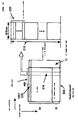
- Fig. 1 shows constituent components of an input/output mechanism (an input/output channel) for data between a tape 10 and a host 70 in an LTO drive.
- Arrows A to D indicate steps of a transfer flow for data read from the tape 10.
- the data read from the tape 10 is temporarily written into an external buffer 30 by a Buffer Manager 40 (Step A).
- the external buffer 30 is, for example, a DDR SDRAM since a broadband is required, and the bus width thereof is 4 bytes or 8 bytes.
- the data written into the external buffer 30 is transferred to an SRAM in an ECC engine (specifically, a C2ECC 50) (Step B).
- the C2ECC 50 corrects errors in all the data and rewrites the corrected data into the DDR SDRAM 30 (Step C).
- the corrected data is transferred as needed to the host 70 according to a request from the DDR SDRAM 30 (Step D).
- the external buffer 30 is accessed for Read or Write by the channel 10 side, the host 70 side or the C2ECC engine 50.
- the Buffer Manager 40 controls the access to the external buffer 30.
- the Buffer Manager 40 is provided as a function of a data flow controller or an ASIC.
- the data (data set) read from the channel 10 is transferred by an interleaved buffer control 20 by each code word pair (CWP) 230 in each row of a sub-data set 200 shown in Fig. 2 .
- the CWP 230 is stored in the DDR SDRAM 30 by the Buffer Manager 40 (Step A).
- the data is compressed as needed and transferred to the host 70 (Step D).
- the Buffer Manager 40 switches between buses in a time-sharing manner so as to enable each of blocks 20, 50 and 60 to efficiently access the DDR SDRAM 30.
- the structure in which the data read from the DDR SDRAM 30 is written back into the DDR SDRAM 30 imposes a strict demand for processing time on the C2ECC 50.
- a data transfer speed defined by the specification can be achieved by performance improvement in each of the components, such as (1) improving performance of an error correction function (C2ECC engine) itself (for example, three times or more higher than that of the conventional case), (2) setting higher an operation clock of the external buffer (DDR SDRAM) 30, and (3) increasing the bus width of the DDR SDRAM, for example.
- C2ECC engine error correction function
- DDR SDRAM external buffer
- burst access can be realized. Since total transfer to the external buffer 30 can be executed by using burst transfer, fast data transfer can be realized. However, in the total transfer, all the data regardless of presence of corrected data are transferred. As a result, waste is incurred in terms of data transfer efficiency.
- Patent Document 1 discloses an invention of which the object is to realize fast access to an external buffer in a digital VTR including an error correction device having a product code (an internal code and an external code) (Paragraph 10).
- the invention described above shares a common characteristic with the present invention in the following point. Specifically, in order to achieve the above object, all input data are transferred to internal code/external code correction means, and corrected data are burst-transferred by bank switching (Paragraphs 17 to 25 and Figs. 1 and 2 ). However, also in Patent Document 1, all the data are burst-transferred to the external buffer regardless of the presence of corrected data. AS a result, data transfer efficiency between a product code correction device and the external buffer is still not improved.
- an object of the present invention to provide an LTO tape drive, a data flow controller and a data flow controlling method of the same, which realize transfer of only an error-corrected sub-unit when corrected data is returned from error correction means to an external buffer.
- the present invention is an information recording device for recording on a recording medium data obtained by adding a correction code to user data of a plurality of bytes transferred from a higher-level device, which corrects an error in the data read from the recording medium by use of the correction code, and which transfers the user data to the higher-level device.
- the information recording device is characterized by comprising: an external buffer for temporarily storing the data read from the recording medium; error correction means which corrects an error in the data transferred from the external buffer to generate corrected data, which divides the corrected data into a plurality of sub-units, and which adds a transfer flag to the sub-units including the corrected data; and data flow means which transfers to the external buffer only a sub-unit having the transfer flag added thereto when the corrected data is to be transferred from the error correction means to the external buffer, and which rewrites only a part corresponding to the sub-unit in the data stored in the external buffer.
- data in a two-dimensional byte matrix in the external buffer in the information recording device of the present invention is a sub-data set including 64 rows ⁇ 480 columns, 64 rows ⁇ 484 columns, 64 rows ⁇ 488 columns or 64 rows ⁇ 492 columns.
- the data flow means in the information recording device of the present invention is characterized in that the data flow means thereof transfers a sub-data set stored in the external buffer, when the data is transferred from the external buffer to the error correction means, by using a unit (64 ⁇ x), as a unit, having a two-dimensional byte matrix in which an integral multiple (x bytes) of a bus width of the external buffer is set to be a division unit for 480, 484, 488 or 492 bytes in the row direction.
- the error correction means in the information recording device of the present invention is characterized in that the error correction means thereof divides the unit (64 ⁇ x) transferred from the external buffer into a plurality of sub-units (y ⁇ x) in a two-dimensional byte matrix by a unit of y rows, and adds a transfer flag to a sub-unit corrected in the error correction; moreover, the data flow means transfers only the sub-unit having the transfer flag added thereto, and rewrites a part corresponding to the sub-unit in the external buffer.
- the information recording device of the present invention also includes an LTO tape drive including a head having a plurality of write and read channels for recording and reading data in a running direction (length direction) of a tape recording medium.
- the LTO drive is characterized in that in the LTO drive, the tape recording medium is divided into data bands corresponding to the head in a width direction. Each of the data bands is divided into a plurality of data sub-bands corresponding to the respective channels in the head. Each of the data sub-bands includes a plurality of tracks accessed by one of the channels.
- code word pairs (CWPs) in each of the rows of the sub-data set stored in the external buffer are sequentially written into tracks in the other data sub-band at a predetermined interval specified by a rotation method. Furthermore, only the sub-unit having the transfer flag added thereto is transferred to the external buffer in the error correction.
- CWPs code word pairs
- the LTO drive of the present invention is characterized in that in the LTO drive thereof, the head has 16 channels, the tape recording medium is divided into 4 data bands, each of the data bands is divided into 16 data sub-bands, and each of the data sub-bands includes 11 tracks.
- the LTO drive of the present invention is not limited to the above configuration. For example, it is also possible to realize an LTO drive having a configuration in which a head has 8 channels, each of data bands is divided into 8 data sub-bands, and each of the data sub-bands includes 12 or 16 tracks.
- the LTO drive of the present invention is characterized in that in the LTO drive thereof, the rotation method is adopted, in which CWPs in each of the rows of the sub-data set are sequentially written into tracks in the other data sub-band by shifting six or one of the data sub-bands.
- the present invention also includes a data flow controller for controlling a data flow in an information recording device for recording on a recording medium data obtained by adding a correction code to user data of a plurality of bytes transferred from a higher-level device, which corrects an error in the data read out in response to a request from the higher-level device by use of the correction code, and which transfers the user data from the corrected data to the higher-level device.
- the data flow controller includes: error correction means which receives data read from the recording medium and temporarily stored in an external buffer, corrects an error in the data to generate corrected data, divides the corrected data into a plurality of sub-units, and which adds a transfer flag to the sub-units including the corrected data; and data flow means which transfers to the external buffer only a sub-unit having the transfer flag when the corrected data is to be transferred to the external buffer, and which rewrites only a part corresponding to the sub-unit in the data stored in the external buffer.
- the present invention also includes a data flow controlling method for recording on a recording medium data obtained by adding a correction code to user data of a plurality of bytes transferred from a higher-level device, for correcting an error in the data read out in response to a request from the higher-level device by use of the correction code to generate corrected data, and for transferring the corrected data to the higher-level device.
- the data flow controlling method is characterized by comprising the steps of: receiving the data read from the recording medium and temporarily stored in an external buffer, correcting an error in the data, dividing the corrected data into a plurality of sub-units, and adding a transfer flag to the sub-units including corrected byte data; and transferring to the external buffer only a sub-unit having the transfer flag when the corrected data is to be transferred to buffer means, and rewriting only a part corresponding to the sub-unit in the data stored in the external buffer.
- the present invention having the configuration as described above has an advantageous effect that can contribute to faster transfer of the data on the recording medium as a whole as long as the data flow can be made more efficient when the corrected data is transferred from the C2ECC engine 50 to the external buffer 30.
- the data on the recording medium can be efficiently error-corrected and transferred without taking into consideration improvement in performance of existing electronic components.
- transfer of the data corrected by the error correction means can be limited to transfer of only a few error-corrected sub-units. As a result, system power consumption of the information recording device can be reduced.
- a third generation LTO magnetic tape drive will be described in detail according to a best mode for carrying out the invention (hereinafter referred to as an embodiment) of the present invention.
- data flow control of the present invention is not limited to the embodiment but can be applied to each generation of an LTO drive and other information recording devices for correcting errors due to a defective medium and defective write and read channels by use of an ECC correction code.
- a unit of data to be transferred is called a data set.
- the data set includes a plurality of (for example, 16 or 64) sub-data sets.
- the data transferred is temporarily stored, by control of a Buffer Manager 40, in an external buffer 30, for example, a DDR SDRAM by the sub-data set as a unit.
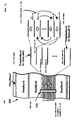
- Fig. 2 shows a sub-data set 200 (left side) in the external buffer 30 and a unit (a C2 unit 210 and a C2 sub-unit 220) (right side) of data transferred between the external buffer 30 and error correction means 50.
- a data flow controlling method for C2 error corrected data in the third generation LTO tape drive One row (480 bytes, 484 bytes, 488 bytes, 492 bytes or the like) obtained by adding a C1 correction code (12 bytes, 16 bytes, 20 bytes, 24 bytes or the like) to 468 bytes of user data is called a code word pair 230 (CWP).
- the data is recorded on a tape by using the CWP 230 as a basic unit.
- One sub-data set is formed of 64 rows of the CWPs including 10 rows of C2 correction codes.
- a unit of read from the tape is a data set.
- a sub-data set is used as a basic unit and 64 sub-data sets are sequentially piled up.
- the sub-data set 200 is used as a unit and the sub-data sets are sequentially and temporarily stored.
- An error correction means 50 includes a C2ECC engine.
- a C1 parity is not written back into the external buffer since the C1 parity is added (On the fly) while transferring 468 bytes of the user data in the CWP.
- the C2ECC engine generates 10 bytes of the C2 correction code for 54 bytes in a vertical direction (a column direction).
- the C2ECC engine 50 will be mainly described. However, the present invention is not limited thereto. The following discussion is also applicable to a multi-dimensional ECC engine.
- a unit of data transferred from the external buffer 30 to the C2ECC 50 is called the C2 unit 210 obtained by dividing the sub-data set in the column direction.
- a data flow controller of the third generation LTO divides the CWP in the row direction by 32 bytes as the C2 unit 210 and transfers 32 columns thereof as a unit from the external buffer 30 to the C2ECC engine 50.
- the C2 sub-unit 220 is obtained by dividing the C2 unit 210 in the column direction into 8 sub-units, each sub-unit including 8 rows.
- a size of the C2 sub-unit 220 (32 bytes ⁇ 8 rows) is a minimum unit of one transfer cycle to the buffer.
- the present invention is characterized in that, while the unit of data sent from the external buffer 30 to the C2ECC engine 50 is the C2 unit, the unit of data rewritten into the external buffer 30 is the C2 sub-unit 220 obtained by dividing the C2 unit 210.
- the data flow controller rewrites the C2 sub-unit into the external data buffer 30.
- the C2 sub-unit including no corrected data in the C2 unit is not returned to the external buffer.
- the corrected data is unevenly distributed in the C2 unit, only the C2 sub-unit including the corrected data may be transferred.
- data transfer efficiency can be improved.
- unnecessary transfer of the C2 unit can be reduced.
- power consumption of the LTO drive can be reduced.
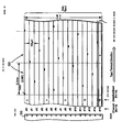
- Fig. 3 shows a physical format of a track on a third generation LTO tape 300.
- a defect such as dust and a scratch on the tape and defective read and write channels cause data errors.
- a write method called rotation of the CWP in each row will be described.
- description will be given of a positional relationship between the C2 sub-unit 220 and the track on the LTO tape.
- potential defects exist.
- tracks (data) on the tape are easily influenced by the defects. Consequently, in the LTO, specified is writing by rotation of the CWP 230 in each row of the sub-data set 200 by considering shapes and positions of the defects on the tape (Nonpatent Document 1).
- the left side of Fig. 3 shows a state where the tape 300 is divided in its width direction into four data bands by servo bands.
- a tape head 310 reads and writes each of the data bands.
- the center part of Fig. 3 shows a configuration of each data band including a plurality of (for example, 16) data sub-bands.
- the respective data sub-bands (#0 to #15) are accessed by corresponding channels (#0 to #15) included in one tape head 310.
- the right side of Fig. 3 shows a track structure in one data sub-band accessed by one channel in the tape head.
- one data sub-band includes 11 tracks.
- the 11 track are accessed by one channel while changing directions.
- One channel first accesses an outer physical track as indicated by an arrow.
- the channel When reaching an end of the track, in other words, an end of the tape, the channel turns to and accesses a track on an opposite side indicated by a dotted line.
- the tracks are accessed by the channel while changing the directions sequentially from the outer track to an inner track.
- the tracks at the same position in the 16 data sub-bands are simultaneously accessed one by one in parallel by the 16 channels (#0 to #15) in the tape head.
- Fig. 4 shows a relationship between details of the physical format of the data band shown in the center part of Fig. 3 and the CWP in each row of the sub-data set.
- the data (CWP) in each row of the sub-data set is written into another data sub-band by another channel.
- the data transferred from the host is written into the tracks in the data sub-band using the CWP as a unit by each of the 16 channels included in the tape head.
- the data sub-bands # into which the data is to be written, are shifted in order to disperse errors due to the defect.
- Fig. 4 shows a mode of wiring the CWP in each row of one sub-data set by use of a rotation method for sequentially shifting six data sub-bands. For example, one CWP in one sub-data set is recorded by the channel #0 on tracks in the corresponding data sub-band #0. The CWP in the next row is recorded on tracks in the data sub-band #6 by the channel #6.
- the CWPs in each of the rows of the sub-data set 200 are sequentially recorded toward the right side on the tracks in the 16 data sub-bands #0 to #15 in the vertical direction.
- Each of packets in black shown in Fig. 4 means the CWP 230 ( Fig. 2 ) in one row.
- the black packets are the CWPs in each of the rows of the same sub-data set and correspond to the CWPs in the rows of the sub-data set sequentially from the left. For example, the leftmost packet on the track in the data sub-band #0 corresponds to the CWP in the first row of the sub-data set 200 shown in Fig. 2 .
- the packet in the data sub-band #6 corresponds to the CWP in the second row of the same sub-data set
- the packet in the data sub-band #12 corresponds to the CWP in the third row of the same sub-data set.
- the black packet (CWP) has a width of one track
- the width of each packet (CWP) is enlarged and shown in Fig. 4 for convenience of explanation.
- Fig. 4 it is found out that the first 8 packets are included in the same C2 sub-unit 220 (see Fig. 2 ).
- Fig. 4 shows the data (CWPs) included in the same C2 sub-unit 220 by using dotted lines to separate the data from that in another sub-unit.
- Fig. 5 shows an example of a typical defect distribution in one data band on the tape.
- Read errors caused by defects on the tape are classified into several types according to the defects such as adhesion of dust and the like, scratches and defective channels.
- shapes of the defects are classified into the following five types. Note, however, that the defects arc assumed to be those having a band shape with a width of about 5 mm or those having a width of about 10 mm.
- the C2ECC engine often cannot correct the sub-data set.
- minor read errors can be sufficiently corrected by the C1ECC engine using a C1 correction code.
- the last defect 5 among those described above is called a dead track, which is an error due to a defective channel or the like and is considered to be one of the defects.
- the defect 5 represents a case where the entire data sub-band 14 cannot be read.
- the packets (CWPs) included in the data sub-band #14 are included in every other C2 sub-unit. Moreover, it is required to correct four errors among the eight C2 sub-units in one C2 unit.
- the C2 sub-units to be transferred from the C2ECC engine 50 to the external buffer 30 can be limited to two out of the eight C2 sub-units in the C2 unit.
- the above reduction in the C2 sub-units to be transferred also has an effect of reduction in power consumption of a system including also the buffer.
- the third generation LTO is required to realize faster transfer compared to the second generation LTO.
- the bus width of the external buffer 30 is increased from 4 bytes in the second generation to 8 bytes. Consequently, in the third generation LTO, 8 bytes is defined as 1 word.
- the data flow controller of the LTO transfers 168 words in total to the external buffer 30 in one bus cycle.
- a band width of the C2ECC engine occupies one C2 sub-unit, in other words, 32 words out of 168 words.
- the present invention is not limited to the technical field of the tape drive described above.
- the unit of data to be processed by the ECC engine will be increased in the future.
- the data flow controlling method of the present invention can be applied to a storage device having a configuration as described above, unnecessary data transfer from the ECC engine to the external buffer can be avoided.
- the present invention provides an information recording device for recording on a recording medium data obtained by adding a correction code to user data of a plurality of bytes transferred from a higher-level device, which corrects an error in the data read from the recording medium by use of the correction code, and for transferring the user data to the higher-level device
- the information recording device characterized by comprising: an external buffer for temporarily storing the data read from the recording medium; error correction means which corrects an error in the data transferred from the external buffer to generate corrected data, which divides the corrected data into a plurality of sub-units, and which adds a transfer flag to the sub-units including the corrected data; and data flow means which transfers to the external buffer only a sub-unit having the transfer flag added thereto when the corrected data is to be transferred from the error correction means to the external buffer, and which rewrites only a part corresponding to the sub-unit in the data stored in the external buffer.
- the present invention provides an apparatus wherein the apparatus is further characterized in that: the data is formed of a two-dimensional byte matrix as a basic unit, the byte matrix including a plurality of rows (one row is horizontal byte data) ⁇ a plurality of columns (one column is vertical byte data), the rows of byte data include a first correction code generated by the error correction means in the user data, and the columns of byte data include a second correction code generated by the error correction means in the user data.
- the present invention provides an apparatus wherein the apparatus is further characterized in that: the data is stored in the external buffer by using a two-dimensional byte matrix including M rows ⁇ N columns as a unit, N bytes of the rows include a first correction code (p bytes) generated by the error correction means in the user data (n bytes), and M bytes of the columns include a second correction code (q bytes) generated by the error correction means in the user data (m bytes).
- N bytes of the rows include a first correction code (p bytes) generated by the error correction means in the user data (n bytes)
- M bytes of the columns include a second correction code (q bytes) generated by the error correction means in the user data (m bytes).
- the present invention provides an apparatus wherein the apparatus is further characterized in that: the data flow means transfers a sub-data set stored in the external buffer, when the data is transferred from the external buffer to the error correction means, by using a second unit (64 ⁇ x), as a unit, having a two-dimensional byte matrix in which an integral multiple (x bytes) of a bus width of the external buffer is set to be a division unit for N in the row direction.
- a second unit 64 ⁇ x
- the data flow means transfers a sub-data set stored in the external buffer, when the data is transferred from the external buffer to the error correction means, by using a second unit (64 ⁇ x), as a unit, having a two-dimensional byte matrix in which an integral multiple (x bytes) of a bus width of the external buffer is set to be a division unit for N in the row direction.
- the present invention provides an apparatus wherein the apparatus is further characterized in that: the error correction means divides the unit (64 ⁇ x) transferred from the external buffer into a plurality of sub-units (y ⁇ x) in a two-dimensional byte matrix by a unit of y rows, and adds a transfer flag to a sub-unit corrected in the error correction, and the data flow means transfers only the sub-unit having the transfer flag added thereto, and rewrites a part corresponding to the sub-unit in the external buffer.
- the error correction means divides the unit (64 ⁇ x) transferred from the external buffer into a plurality of sub-units (y ⁇ x) in a two-dimensional byte matrix by a unit of y rows, and adds a transfer flag to a sub-unit corrected in the error correction
- the data flow means transfers only the sub-unit having the transfer flag added thereto, and rewrites a part corresponding to the sub-unit in the external buffer.
- the present invention provides an apparatus wherein the apparatus is further characterized in that: the information recording device is an LTO drive including a head having a plurality of write and read channels for recording and reading the data in a running direction (length direction) of a tape recording medium, the tape recording medium is divided into data bands corresponding to the head in a width direction, each of the data bands is divided into a plurality of data sub-bands corresponding to the respective channels in the head, each of the data sub-bands includes a plurality of tracks accessed by one of the channels, code word pairs (CWPs) in each of the rows of the sub-data set stored in the external buffer are sequentially written into tracks in the other data sub-band at a predetermined interval specified by a rotation method, and only the sub-unit having the transfer flag added thereto is transferred to the external buffer in the error correction.
- the information recording device is an LTO drive including a head having a plurality of write and read channels for recording and reading the data in a running direction (length direction) of a tape recording medium
- the present invention provides an apparatus wherein the apparatus is further characterized in that: the head has 16 channels, the tape recording medium is divided into 4 data bands, each of the data bands is divided into 16 data sub-bands, and each of the data sub-bands includes 11 tracks.
- the present invention provides an apparatus wherein the apparatus is further characterized in that: in the rotation method, CWPs in each of the rows of the sub-data set are sequentially written into tracks in the other data sub-band by shifting six of the data sub-bands.
- the present invention provides a data flow controller for controlling a data flow in an information recording device for recording on a recording medium data obtained by adding a correction code to user data of a plurality of bytes transferred from a higher-level device, which corrects an error in the data read out in response to a request from the higher-level device by use of the correction code to generate corrected data, and which transfers the user data from the corrected data to the higher-level device, characterized by comprising: error correction means which receives data read from the recording medium and temporarily stored in an external buffer, corrects an error in the data, which divides the corrected data into a plurality of sub-units, and which adds a transfer flag to the sub-units including the corrected data; and data flow means which transfers to the external buffer only a sub-unit having the transfer flag when the corrected data is to be transferred to the external buffer, and which rewrites only a part corresponding to the sub-unit in the data stored in the external buffer.
- a second unit 64 ⁇ x
- the present invention provides an apparatus wherein the apparatus is further characterized in that: the error correction means divides the unit (64 ⁇ x) transferred from the external buffer into a plurality of sub-units (y ⁇ x) in a two-dimensional byte matrix by a unit of y rows, and adds a transfer flag to a sub-unit corrected in the error correction, and the data flow means transfers only the sub-unit having the transfer flag added thereto, and rewrites a part corresponding to the sub-unit in the external buffer.
- the error correction means divides the unit (64 ⁇ x) transferred from the external buffer into a plurality of sub-units (y ⁇ x) in a two-dimensional byte matrix by a unit of y rows, and adds a transfer flag to a sub-unit corrected in the error correction
- the data flow means transfers only the sub-unit having the transfer flag added thereto, and rewrites a part corresponding to the sub-unit in the external buffer.
- the present invention provides a data flow controlling method for recording on a recording medium data obtained by adding a correction code to user data of a plurality of bytes transferred from a higher-level device, for correcting an error in the data read out in response to a request from the higher-level device by use of the correction code to generate corrected data, and for transferring the corrected data to the higher-level device, the method characterized by comprising the steps of: receiving the data read from the recording medium and temporarily stored in an external buffer, correcting an error in the data, dividing the corrected data into a plurality of sub-units, and adding a transfer flag to the sub-units including corrected byte data; and transferring to the external buffer only a sub-unit having the transfer flag when the corrected data is to be transferred to buffer means, and rewriting only a part corresponding to the sub-unit in the data stored in the external buffer.
Landscapes
- Engineering & Computer Science (AREA)
- Signal Processing (AREA)
- Theoretical Computer Science (AREA)
- Physics & Mathematics (AREA)
- General Engineering & Computer Science (AREA)
- General Physics & Mathematics (AREA)
- Quality & Reliability (AREA)
- Signal Processing For Digital Recording And Reproducing (AREA)
Claims (10)
- Datenaufzeichnungseinheit für das Aufzeichnen von Daten auf einem Aufzeichnungsmedium (10), die erhalten werden, indem ein Korrekturcode zu Benutzerdaten aus einer Vielzahl von Bytes, die von einer übergeordneten Einheit übertragen werden, hinzugefügt wird, die anhand des Korrekturcodes einen Fehler in den Daten, die aus dem Aufzeichnungsmedium gelesen werden, korrigiert, sowie für das Übertragen der Benutzerdaten an die übergeordnete Einheit, wobei die Datenaufzeichnungseinheit dadurch gekennzeichnet ist, dass sie Folgendes umfasst:einen externen Pufferspeicher (30) für das vorübergehende Speichern der aus dem Aufzeichnungsmedium gelesenen Daten;ein Fehlerkorrekturmittel (50), das einen Fehler in den von dem externen Pufferspeicher übertragenen Daten korrigiert, um korrigierte Daten zu erzeugen, das die korrigierten Daten in eine Vielzahl von Teileinheiten (220) unterteilt, wobei eine Teileinheit eine Vielzahl von Bytes umfasst, und das den Teileinheiten, welche die korrigierten Daten enthalten, eine Übertragungsmarkierung hinzufügt, wobei eine Übertragungsmarkierung angibt, ob eine Teileinheit korrigierte Daten umfasst; undein Datenflussmittel (40), das, wenn die korrigierten Daten von dem Fehlerkorrekturmittel an den externen Pufferspeicher übertragen werden sollen, lediglich eine Teileinheit, der die Übertragungsmarkierung hinzugefügt wurde, überträgt und das in den Daten, die in dem externen Pufferspeicher gespeichert sind, lediglich einen Teil erneut schreibt, welcher der Teileinheit entspricht.
- Datenaufzeichnungseinheit nach Anspruch 1, dadurch gekennzeichnet, dass:die Daten aus einer zweidimensionalen Byte-Matrix (200) als grundlegender Einheit gebildet werden, wobei die Byte-Matrix eine Vielzahl von Zeilen (eine Zeile besteht aus horizontalen Byte-Daten) multipliziert mit einer Vielzahl von Spalten (eine Spalte besteht aus vertikalen Byte-Daten) enthält,die Zeilen von Byte-Daten einen ersten Korrekturcode (C1) enthalten, der durch das Fehlerkorrekturmittel in den Benutzerdaten erzeugt wurde, unddie Spalten von Byte-Daten einen zweiten Korrekturcode (C2) enthalten, der durch das Fehlerkorrekturmittel in den Benutzerdaten erzeugt wurde.
- Datenaufzeichnungseinheit nach Anspruch 2, dadurch gekennzeichnet, dass:die Daten in dem externen Pufferspeicher gespeichert werden, indem eine zweidimensionale Byte-Matrix verwendet wird, die als Einheit M Zeilen x N Spalten enthält,N Bytes der Zeilen einen ersten Korrekturcode (p Bytes) enthalten, der durch das Fehlerkorrekturmittel in den Benutzerdaten (n Bytes) erzeugt wurde, undM Bytes der Spalten einen zweiten Korrekturcode (q Bytes) enthalten, der durch das Fehlerkorrekturmittel in den Benutzerdaten (m Bytes) erzeugt wurde.
- Datenaufzeichnungseinheit nach Anspruch 3, dadurch gekennzeichnet, dass:die zweidimensionale Byte-Matrix ein Teildatensatz mit 64 Zeilen x 480 Spalten, 64 Zeilen x 484 Spalten, 64 Zeilen x 488 Spalten oder 64 Zeilen x 492 Spalten (M = 64; N = 480, 484, 488 oder 492) ist,N = 480, 484, 488 oder 492 Bytes der Zeilen einen ersten Korrekturcode (p = 12, 16, 20 oder 24 Bytes) in n = 468 Bytes der Benutzerdaten enthalten, und64 Bytes der Spalten m = 54 Bytes der Benutzerdaten und einen zweiten Korrekturcode (q = 10 Bytes) enthalten.
- Datenaufzeichnungseinheit nach Anspruch 4, dadurch gekennzeichnet, dass:das Datenflussmittel, wenn die Daten von dem externen Pufferspeicher an das Fehlerkorrekturmittel übertragen werden, einen in dem externen Pufferspeicher gespeicherten Teildatensatz überträgt, indem eine zweite Einheit (64 mal x) als Einheit verwendet wird, die eine zweidimensionale Byte-Matrix aufweist, bei der als Teilungseinheit für N in Zeilenrichtung ein ganzzahliges Mehrfaches (x Bytes) einer Busbreite des externen Pufferspeichers gesetzt wird.
- Datenaufzeichnungseinheit nach Anspruch 5, dadurch gekennzeichnet, dass:der externe Pufferspeicher ein DDR-SDRAM ist,die Teilungseinheit x = 4, 8, 16, 32 oder 64 Bytes ist unddie Einheit (64 mal x) eine zweidimensionale Byte-Matrix mit 64 x 4, 64 x 8, 64 x 16, 64 x 32 oder 64 x 64 Bytes ist.
- Datenfluss-Steuereinheit für das Steuern eines Datenflusses in einer Datenaufzeichnungseinheit für das Aufzeichnen von Daten (10) auf einem Aufzeichnungsmedium, die erhalten werden, indem ein Korrekturcode zu Benutzerdaten aus einer Vielzahl von Bytes, die von einer übergeordneten Einheit übertragen werden, hinzugefügt wird, die anhand des Korrekturcodes einen Fehler in den Daten, die als Reaktion auf eine Anforderung aus der übergeordneten Einheit gelesen werden, korrigiert, um korrigierte Daten zu erzeugen, und welche die Benutzerdaten von den korrigierten Daten an die übergeordnete Einheit überträgt, dadurch gekennzeichnet, dass sie Folgendes umfasst:ein Fehlerkorrekturmittel (50), das Daten empfängt, die aus dem Aufzeichnungsmittel gelesen und vorübergehend in einem externen Pufferspeicher (30) gespeichert wurden, das einen Fehler in den Daten korrigiert, das die korrigierten Daten in eine Vielzahl von Teileinheiten (220) unterteilt, wobei eine Teileinheit eine Vielzahl von Bytes umfasst, und das den Teileinheiten, welche die korrigierten Daten enthalten, eine Übertragungsmarkierung hinzufügt, wobei eine Übertragungsmarkierung angibt, ob eine Teileinheit korrigierte Daten umfasst; undein Datenflussmittel (40), das, wenn die korrigierten Daten an den externen Pufferspeicher übertragen werden sollen, lediglich eine Teileinheit mit der Übertragungsmarkierung an den externen Pufferspeicher überträgt, und das in den Daten, welche in dem externen Datenpuffer gespeichert sind, lediglich einen Teil erneut schreibt, welcher der Teileinheit entspricht.
- Datenfluss-Steuereinheit nach Anspruch 7, dadurch gekennzeichnet, dass:die Daten aus einer zweidimensionalen Byte-Matrix (200) gebildet werden, bei der es sich um einen Teildatensatz handelt, der 64 Zeilen x 480 Spalten, 64 Zeilen x 484 Spalten, 64 Zeilen x 488 Spalten oder 64 Zeilen x 492 Spalten enthält,480, 484, 488 oder 492 Bytes der Zeilen einen ersten Korrekturcode (C1) mit 12, 16, 20 oder 24 Bytes in n = 468 Bytes der Benutzerdaten enthalten, und64 Bytes an Daten in den Spalten die Benutzerdaten mit 54 Bytes und einen zweiten Korrekturcode (C2) mit 10 Bytes enthalten.
- Datenfluss-Steuereinheit nach Anspruch 8, dadurch gekennzeichnet, dass:das Datenflussmittel, wenn die Daten von dem externen Pufferspeicher an das Fehlerkorrekturmittel übertragen werden, einen in dem externen Pufferspeicher gespeicherten Teildatensatz überträgt, indem eine zweite Einheit (64 mal x) als Einheit verwendet wird, die eine zweidimensionale Byte-Matrix aufweist, bei der als Teilungseinheit für N Bytes (N = 480, 484, 488 oder 492) in Zeilenrichtung ein ganzzahliges Mehrfaches (x Bytes) einer Busbreite des externen Pufferspeichers gesetzt wird.
- Datenfluss-Steuereinheit nach Anspruch 9, dadurch gekennzeichnet, dass:das Fehlerkorrekturmittel die von dem externen Pufferspeicher übertragene Einheit (64 mal x) in eine Vielzahl von Teileinheiten (y mal x) in einer zweidimensionalen Byte-Matrix mit einer Einheit von y Zeilen unterteilt und einer Teileinheit, die bei der Fehlerkorrektur korrigiert wurde, eine Übertragungsmarkierung hinzufügt, unddas Datenfluss-Steuermittel nur die Teileinheit überträgt, der die Übertragungsmarkierung hinzugefügt wurde, und in dem externen Pufferspeicher einen Teil neu schreibt, welcher der Teileinheit entspricht.
Applications Claiming Priority (2)
| Application Number | Priority Date | Filing Date | Title |
|---|---|---|---|
| JP2004378509 | 2004-12-28 | ||
| PCT/JP2005/023488 WO2006070668A1 (ja) | 2004-12-28 | 2005-12-21 | 情報記録装置、そのデータフロー・コントローラ、及びそのデータフローの制御方法 |
Publications (3)
| Publication Number | Publication Date |
|---|---|
| EP1850342A1 EP1850342A1 (de) | 2007-10-31 |
| EP1850342A4 EP1850342A4 (de) | 2009-04-08 |
| EP1850342B1 true EP1850342B1 (de) | 2012-12-05 |
Family
ID=36614787
Family Applications (1)
| Application Number | Title | Priority Date | Filing Date |
|---|---|---|---|
| EP05820131A Expired - Lifetime EP1850342B1 (de) | 2004-12-28 | 2005-12-21 | INFORMATIONSAUFZEICHNUNGSEINRICHTUNG und DATENFLUSSSTEUERUNG FÜR DIE EINRICHTUNG |
Country Status (6)
| Country | Link |
|---|---|
| US (1) | US7987404B2 (de) |
| EP (1) | EP1850342B1 (de) |
| JP (1) | JP4272678B2 (de) |
| KR (1) | KR100915650B1 (de) |
| CN (1) | CN101091214B (de) |
| WO (1) | WO2006070668A1 (de) |
Families Citing this family (36)
| Publication number | Priority date | Publication date | Assignee | Title |
|---|---|---|---|---|
| US8065583B2 (en) | 2007-07-06 | 2011-11-22 | Micron Technology, Inc. | Data storage with an outer block code and a stream-based inner code |
| US8051358B2 (en) | 2007-07-06 | 2011-11-01 | Micron Technology, Inc. | Error recovery storage along a nand-flash string |
| US7746588B2 (en) * | 2007-09-14 | 2010-06-29 | International Business Machines Corporation | Tape-based data storage system capable of reading and/or writing multiple error correctable sets of data |
| US8046542B2 (en) | 2007-11-21 | 2011-10-25 | Micron Technology, Inc. | Fault-tolerant non-volatile integrated circuit memory |
| US8327245B2 (en) | 2007-11-21 | 2012-12-04 | Micron Technology, Inc. | Memory controller supporting rate-compatible punctured codes |
| US8499229B2 (en) | 2007-11-21 | 2013-07-30 | Micro Technology, Inc. | Method and apparatus for reading data from flash memory |
| DE102008057910B4 (de) | 2008-11-18 | 2010-10-07 | P&L Edv Systeme Gmbh | Patientenverwaltungssystem mit intelligenter Schnittstelleneinrichtung zur Übertragung medizinischer Daten |
| US7876516B2 (en) * | 2009-01-09 | 2011-01-25 | International Business Machines Corporation | Rewrite-efficient ECC/interleaving for multi-track recording on magnetic tape |
| US8386895B2 (en) | 2010-05-19 | 2013-02-26 | Micron Technology, Inc. | Enhanced multilevel memory |
| JP5536565B2 (ja) | 2010-06-30 | 2014-07-02 | インターナショナル・ビジネス・マシーンズ・コーポレーション | テープ媒体にデータを書き込む装置及び方法 |
| US9021333B1 (en) | 2012-05-22 | 2015-04-28 | Pmc-Sierra, Inc. | Systems and methods for recovering data from failed portions of a flash drive |
| US8972824B1 (en) | 2012-05-22 | 2015-03-03 | Pmc-Sierra, Inc. | Systems and methods for transparently varying error correction code strength in a flash drive |
| US9183085B1 (en) | 2012-05-22 | 2015-11-10 | Pmc-Sierra, Inc. | Systems and methods for adaptively selecting from among a plurality of error correction coding schemes in a flash drive for robustness and low latency |
| US9047214B1 (en) | 2012-05-22 | 2015-06-02 | Pmc-Sierra, Inc. | System and method for tolerating a failed page in a flash device |
| US9176812B1 (en) | 2012-05-22 | 2015-11-03 | Pmc-Sierra, Inc. | Systems and methods for storing data in page stripes of a flash drive |
| US9021337B1 (en) | 2012-05-22 | 2015-04-28 | Pmc-Sierra, Inc. | Systems and methods for adaptively selecting among different error correction coding schemes in a flash drive |
| US9021336B1 (en) | 2012-05-22 | 2015-04-28 | Pmc-Sierra, Inc. | Systems and methods for redundantly storing error correction codes in a flash drive with secondary parity information spread out across each page of a group of pages |
| US8996957B1 (en) | 2012-05-22 | 2015-03-31 | Pmc-Sierra, Inc. | Systems and methods for initializing regions of a flash drive having diverse error correction coding (ECC) schemes |
| US8788910B1 (en) | 2012-05-22 | 2014-07-22 | Pmc-Sierra, Inc. | Systems and methods for low latency, high reliability error correction in a flash drive |
| US8793556B1 (en) | 2012-05-22 | 2014-07-29 | Pmc-Sierra, Inc. | Systems and methods for reclaiming flash blocks of a flash drive |
| US9577673B2 (en) | 2012-11-08 | 2017-02-21 | Micron Technology, Inc. | Error correction methods and apparatuses using first and second decoders |
| US8793552B2 (en) | 2012-11-14 | 2014-07-29 | International Business Machines Corporation | Reconstructive error recovery procedure (ERP) for multiple data sets using reserved buffer |
| US9053748B2 (en) * | 2012-11-14 | 2015-06-09 | International Business Machines Corporation | Reconstructive error recovery procedure (ERP) using reserved buffer |
| US9009565B1 (en) | 2013-03-15 | 2015-04-14 | Pmc-Sierra, Inc. | Systems and methods for mapping for solid-state memory |
| US9053012B1 (en) | 2013-03-15 | 2015-06-09 | Pmc-Sierra, Inc. | Systems and methods for storing data for solid-state memory |
| US9026867B1 (en) | 2013-03-15 | 2015-05-05 | Pmc-Sierra, Inc. | Systems and methods for adapting to changing characteristics of multi-level cells in solid-state memory |
| US9208018B1 (en) | 2013-03-15 | 2015-12-08 | Pmc-Sierra, Inc. | Systems and methods for reclaiming memory for solid-state memory |
| US9081701B1 (en) | 2013-03-15 | 2015-07-14 | Pmc-Sierra, Inc. | Systems and methods for decoding data for solid-state memory |
| US8810944B1 (en) | 2013-07-16 | 2014-08-19 | International Business Machines Corporation | Dynamic buffer size switching for burst errors encountered while reading a magnetic tape |
| JP5932731B2 (ja) * | 2013-07-30 | 2016-06-08 | インターナショナル・ビジネス・マシーンズ・コーポレーションInternational Business Machines Corporation | ホストとの間で映像データを含む複数のレコードを転送するテープドライブ、方法、およびプログラム |
| US9582360B2 (en) | 2014-01-07 | 2017-02-28 | International Business Machines Corporation | Single and multi-cut and paste (C/P) reconstructive error recovery procedure (ERP) using history of error correction |
| US9141478B2 (en) | 2014-01-07 | 2015-09-22 | International Business Machines Corporation | Reconstructive error recovery procedure (ERP) using reserved buffer |
| US9502052B1 (en) | 2015-12-17 | 2016-11-22 | International Business Machines Corporation | Writing redundant data on tape media |
| US10379756B2 (en) | 2016-12-15 | 2019-08-13 | International Business Machines Corporation | Logical format utilizing lateral encoding of data for storage on magnetic tape |
| US11042329B2 (en) | 2019-05-21 | 2021-06-22 | International Business Machines Corporation | Reordering a sequence of files based on compression rates in data transfer |
| US11561703B2 (en) * | 2021-02-10 | 2023-01-24 | International Business Machines Corporation | Adaptive tape calibration criteria by number of dead tracks |
Family Cites Families (14)
| Publication number | Priority date | Publication date | Assignee | Title |
|---|---|---|---|---|
| JPH02162430A (ja) | 1988-12-15 | 1990-06-22 | Fujitsu Ltd | 二重化システムのデータ同期方式 |
| JPH02193366A (ja) | 1989-01-20 | 1990-07-31 | Mitsubishi Electric Corp | ディジタル信号再生装置 |
| JP2640044B2 (ja) | 1991-05-08 | 1997-08-13 | 三洋電機株式会社 | デジタル信号記録媒体再生装置 |
| JP3154607B2 (ja) * | 1993-12-28 | 2001-04-09 | 三菱電機株式会社 | 誤り訂正復号装置及び誤り訂正復号方法 |
| JP3687109B2 (ja) * | 1994-07-29 | 2005-08-24 | ソニー株式会社 | 磁気記録装置 |
| JP3708617B2 (ja) | 1996-03-18 | 2005-10-19 | 株式会社東芝 | Eccメモリ制御システム |
| JP3854697B2 (ja) * | 1997-09-16 | 2006-12-06 | キヤノン株式会社 | 受信装置 |
| EP0913826A1 (de) * | 1997-10-31 | 1999-05-06 | Hewlett-Packard Company | Kratzschutz in einem Magnetbandspeichersystem |
| JP2000057711A (ja) * | 1998-08-07 | 2000-02-25 | Victor Co Of Japan Ltd | 誤り訂正復号装置 |
| JP3592597B2 (ja) | 1999-12-15 | 2004-11-24 | 松下電器産業株式会社 | エラー訂正装置及びプログラム記録媒体 |
| US6751771B2 (en) * | 2000-02-11 | 2004-06-15 | Mediatek, Inc. | Method and apparatus for error processing in optical disk memories |
| JP2001266509A (ja) | 2000-03-17 | 2001-09-28 | Sanyo Electric Co Ltd | 誤り訂正・デスクランブル回路、誤り訂正・デスクランブル回路を備えた再生装置、および誤り訂正・デスクランブル処理を行なう方法 |
| US7042667B2 (en) * | 2001-07-31 | 2006-05-09 | Hewlett-Packard Development Company, L.P. | Data storage |
| US7849381B2 (en) * | 2004-12-21 | 2010-12-07 | Sandisk Corporation | Method for copying data in reprogrammable non-volatile memory |
-
2005
- 2005-12-21 CN CN2005800449999A patent/CN101091214B/zh not_active Expired - Fee Related
- 2005-12-21 US US11/721,446 patent/US7987404B2/en not_active Expired - Fee Related
- 2005-12-21 JP JP2006550711A patent/JP4272678B2/ja not_active Expired - Fee Related
- 2005-12-21 KR KR1020077014419A patent/KR100915650B1/ko not_active Expired - Fee Related
- 2005-12-21 WO PCT/JP2005/023488 patent/WO2006070668A1/ja not_active Ceased
- 2005-12-21 EP EP05820131A patent/EP1850342B1/de not_active Expired - Lifetime
Also Published As
| Publication number | Publication date |
|---|---|
| US7987404B2 (en) | 2011-07-26 |
| US20080320361A1 (en) | 2008-12-25 |
| KR100915650B1 (ko) | 2009-09-04 |
| CN101091214A (zh) | 2007-12-19 |
| JP4272678B2 (ja) | 2009-06-03 |
| EP1850342A4 (de) | 2009-04-08 |
| JPWO2006070668A1 (ja) | 2008-08-07 |
| EP1850342A1 (de) | 2007-10-31 |
| CN101091214B (zh) | 2010-06-09 |
| WO2006070668A1 (ja) | 2006-07-06 |
| KR20070088734A (ko) | 2007-08-29 |
Similar Documents
| Publication | Publication Date | Title |
|---|---|---|
| EP1850342B1 (de) | INFORMATIONSAUFZEICHNUNGSEINRICHTUNG und DATENFLUSSSTEUERUNG FÜR DIE EINRICHTUNG | |
| US7490212B2 (en) | System and method for writing data to dedicated bands of a hard disk drive | |
| US5442752A (en) | Data storage method for DASD arrays using striping based on file length | |
| JP2008052728A (ja) | フラッシュメモリシステム及びそのプログラム方法 | |
| US5274507A (en) | Parallel data encoding for moving media | |
| KR100537577B1 (ko) | 스트리밍 오디오비주얼 데이터를 디스크 드라이브에기록하는 방법 | |
| US20020138694A1 (en) | Magnetic disc drive, method for recording data, and method for reproducing data | |
| US10884654B2 (en) | System and method for quality of service assurance of multi-stream scenarios in a hard disk drive | |
| US5890206A (en) | Method of writing sequential data to a disc memory system having a fixed block architecture | |
| US7770076B2 (en) | Multi-platter disk drive controller and methods for synchronous redundant data operations | |
| EP1486975B1 (de) | Aufzeichnungsmedium, aufzeichnungsverfahren und aufzeichnungs-/wiedergabeeinrichtung | |
| US6499082B1 (en) | Method of transferring data from large capacity data storage device | |
| US12124740B2 (en) | Selective hard and soft rewrites | |
| KR19990072581A (ko) | 데이터전송방법및장치 | |
| US20010052051A1 (en) | Method of controlling data access and system thereof | |
| JP2009223355A (ja) | ハードディスクとシリコンディスクのミラーリングを行うディスク制御システム | |
| JPH05210915A (ja) | ディスク装置 | |
| JP3592597B2 (ja) | エラー訂正装置及びプログラム記録媒体 | |
| US20090043950A1 (en) | Semiconductor memory storage apparatus and content data management method | |
| JPH04264910A (ja) | コンピュータ外部記憶装置のデータ更新方法 | |
| US6987631B2 (en) | Data read/write method and apparatus | |
| JP3874019B2 (ja) | 記憶装置システム | |
| JP2004095024A (ja) | データ記憶装置及びデータ記憶装置におけるデータ交替処理方法 | |
| JPH02300817A (ja) | ディスク制御装置 | |
| JPS6374174A (ja) | 情報再生制御方式 |
Legal Events
| Date | Code | Title | Description |
|---|---|---|---|
| PUAI | Public reference made under article 153(3) epc to a published international application that has entered the european phase |
Free format text: ORIGINAL CODE: 0009012 |
|
| 17P | Request for examination filed |
Effective date: 20070712 |
|
| AK | Designated contracting states |
Kind code of ref document: A1 Designated state(s): AT BE BG CH CY CZ DE DK EE ES FI FR GB GR HU IE IS IT LI LT LU LV MC NL PL PT RO SE SI SK TR |
|
| DAX | Request for extension of the european patent (deleted) | ||
| RIN1 | Information on inventor provided before grant (corrected) |
Inventor name: MATSUO, HISATO Inventor name: FUKUDA, JUNICHI |
|
| A4 | Supplementary search report drawn up and despatched |
Effective date: 20090306 |
|
| 17Q | First examination report despatched |
Effective date: 20090529 |
|
| GRAP | Despatch of communication of intention to grant a patent |
Free format text: ORIGINAL CODE: EPIDOSNIGR1 |
|
| GRAS | Grant fee paid |
Free format text: ORIGINAL CODE: EPIDOSNIGR3 |
|
| GRAA | (expected) grant |
Free format text: ORIGINAL CODE: 0009210 |
|
| AK | Designated contracting states |
Kind code of ref document: B1 Designated state(s): AT BE BG CH CY CZ DE DK EE ES FI FR GB GR HU IE IS IT LI LT LU LV MC NL PL PT RO SE SI SK TR |
|
| REG | Reference to a national code |
Ref country code: GB Ref legal event code: FG4D |
|
| REG | Reference to a national code |
Ref country code: CH Ref legal event code: NV Representative=s name: IBM RESEARCH GMBH ZURICH RESEARCH LABORATORY I, CH Ref country code: CH Ref legal event code: EP |
|
| REG | Reference to a national code |
Ref country code: AT Ref legal event code: REF Ref document number: 587648 Country of ref document: AT Kind code of ref document: T Effective date: 20121215 |
|
| REG | Reference to a national code |
Ref country code: IE Ref legal event code: FG4D |
|
| REG | Reference to a national code |
Ref country code: GB Ref legal event code: 746 Effective date: 20130107 |
|
| REG | Reference to a national code |
Ref country code: DE Ref legal event code: R096 Ref document number: 602005037341 Country of ref document: DE Effective date: 20130131 |
|
| REG | Reference to a national code |
Ref country code: DE Ref legal event code: R084 Ref document number: 602005037341 Country of ref document: DE Effective date: 20121213 |
|
| REG | Reference to a national code |
Ref country code: AT Ref legal event code: MK05 Ref document number: 587648 Country of ref document: AT Kind code of ref document: T Effective date: 20121205 |
|
| PG25 | Lapsed in a contracting state [announced via postgrant information from national office to epo] |
Ref country code: ES Free format text: LAPSE BECAUSE OF FAILURE TO SUBMIT A TRANSLATION OF THE DESCRIPTION OR TO PAY THE FEE WITHIN THE PRESCRIBED TIME-LIMIT Effective date: 20130316 Ref country code: SE Free format text: LAPSE BECAUSE OF FAILURE TO SUBMIT A TRANSLATION OF THE DESCRIPTION OR TO PAY THE FEE WITHIN THE PRESCRIBED TIME-LIMIT Effective date: 20121205 Ref country code: LT Free format text: LAPSE BECAUSE OF FAILURE TO SUBMIT A TRANSLATION OF THE DESCRIPTION OR TO PAY THE FEE WITHIN THE PRESCRIBED TIME-LIMIT Effective date: 20121205 Ref country code: FI Free format text: LAPSE BECAUSE OF FAILURE TO SUBMIT A TRANSLATION OF THE DESCRIPTION OR TO PAY THE FEE WITHIN THE PRESCRIBED TIME-LIMIT Effective date: 20121205 |
|
| REG | Reference to a national code |
Ref country code: NL Ref legal event code: VDEP Effective date: 20121205 |
|
| REG | Reference to a national code |
Ref country code: LT Ref legal event code: MG4D |
|
| PG25 | Lapsed in a contracting state [announced via postgrant information from national office to epo] |
Ref country code: SI Free format text: LAPSE BECAUSE OF FAILURE TO SUBMIT A TRANSLATION OF THE DESCRIPTION OR TO PAY THE FEE WITHIN THE PRESCRIBED TIME-LIMIT Effective date: 20121205 Ref country code: LV Free format text: LAPSE BECAUSE OF FAILURE TO SUBMIT A TRANSLATION OF THE DESCRIPTION OR TO PAY THE FEE WITHIN THE PRESCRIBED TIME-LIMIT Effective date: 20121205 Ref country code: GR Free format text: LAPSE BECAUSE OF FAILURE TO SUBMIT A TRANSLATION OF THE DESCRIPTION OR TO PAY THE FEE WITHIN THE PRESCRIBED TIME-LIMIT Effective date: 20130306 Ref country code: PL Free format text: LAPSE BECAUSE OF FAILURE TO SUBMIT A TRANSLATION OF THE DESCRIPTION OR TO PAY THE FEE WITHIN THE PRESCRIBED TIME-LIMIT Effective date: 20121205 |
|
| PG25 | Lapsed in a contracting state [announced via postgrant information from national office to epo] |
Ref country code: AT Free format text: LAPSE BECAUSE OF FAILURE TO SUBMIT A TRANSLATION OF THE DESCRIPTION OR TO PAY THE FEE WITHIN THE PRESCRIBED TIME-LIMIT Effective date: 20121205 |
|
| PG25 | Lapsed in a contracting state [announced via postgrant information from national office to epo] |
Ref country code: MC Free format text: LAPSE BECAUSE OF NON-PAYMENT OF DUE FEES Effective date: 20121231 Ref country code: BG Free format text: LAPSE BECAUSE OF FAILURE TO SUBMIT A TRANSLATION OF THE DESCRIPTION OR TO PAY THE FEE WITHIN THE PRESCRIBED TIME-LIMIT Effective date: 20130305 Ref country code: IS Free format text: LAPSE BECAUSE OF FAILURE TO SUBMIT A TRANSLATION OF THE DESCRIPTION OR TO PAY THE FEE WITHIN THE PRESCRIBED TIME-LIMIT Effective date: 20130405 Ref country code: BE Free format text: LAPSE BECAUSE OF FAILURE TO SUBMIT A TRANSLATION OF THE DESCRIPTION OR TO PAY THE FEE WITHIN THE PRESCRIBED TIME-LIMIT Effective date: 20121205 Ref country code: SK Free format text: LAPSE BECAUSE OF FAILURE TO SUBMIT A TRANSLATION OF THE DESCRIPTION OR TO PAY THE FEE WITHIN THE PRESCRIBED TIME-LIMIT Effective date: 20121205 Ref country code: CZ Free format text: LAPSE BECAUSE OF FAILURE TO SUBMIT A TRANSLATION OF THE DESCRIPTION OR TO PAY THE FEE WITHIN THE PRESCRIBED TIME-LIMIT Effective date: 20121205 Ref country code: EE Free format text: LAPSE BECAUSE OF FAILURE TO SUBMIT A TRANSLATION OF THE DESCRIPTION OR TO PAY THE FEE WITHIN THE PRESCRIBED TIME-LIMIT Effective date: 20121205 |
|
| REG | Reference to a national code |
Ref country code: CH Ref legal event code: PL |
|
| PG25 | Lapsed in a contracting state [announced via postgrant information from national office to epo] |
Ref country code: NL Free format text: LAPSE BECAUSE OF FAILURE TO SUBMIT A TRANSLATION OF THE DESCRIPTION OR TO PAY THE FEE WITHIN THE PRESCRIBED TIME-LIMIT Effective date: 20121205 Ref country code: RO Free format text: LAPSE BECAUSE OF FAILURE TO SUBMIT A TRANSLATION OF THE DESCRIPTION OR TO PAY THE FEE WITHIN THE PRESCRIBED TIME-LIMIT Effective date: 20121205 Ref country code: PT Free format text: LAPSE BECAUSE OF FAILURE TO SUBMIT A TRANSLATION OF THE DESCRIPTION OR TO PAY THE FEE WITHIN THE PRESCRIBED TIME-LIMIT Effective date: 20130405 |
|
| REG | Reference to a national code |
Ref country code: IE Ref legal event code: MM4A |
|
| PLBE | No opposition filed within time limit |
Free format text: ORIGINAL CODE: 0009261 |
|
| STAA | Information on the status of an ep patent application or granted ep patent |
Free format text: STATUS: NO OPPOSITION FILED WITHIN TIME LIMIT |
|
| PG25 | Lapsed in a contracting state [announced via postgrant information from national office to epo] |
Ref country code: CH Free format text: LAPSE BECAUSE OF NON-PAYMENT OF DUE FEES Effective date: 20121231 Ref country code: DK Free format text: LAPSE BECAUSE OF FAILURE TO SUBMIT A TRANSLATION OF THE DESCRIPTION OR TO PAY THE FEE WITHIN THE PRESCRIBED TIME-LIMIT Effective date: 20121205 Ref country code: LI Free format text: LAPSE BECAUSE OF NON-PAYMENT OF DUE FEES Effective date: 20121231 Ref country code: IE Free format text: LAPSE BECAUSE OF NON-PAYMENT OF DUE FEES Effective date: 20121221 |
|
| 26N | No opposition filed |
Effective date: 20130906 |
|
| REG | Reference to a national code |
Ref country code: FR Ref legal event code: ST Effective date: 20131023 |
|
| PG25 | Lapsed in a contracting state [announced via postgrant information from national office to epo] |
Ref country code: CY Free format text: LAPSE BECAUSE OF FAILURE TO SUBMIT A TRANSLATION OF THE DESCRIPTION OR TO PAY THE FEE WITHIN THE PRESCRIBED TIME-LIMIT Effective date: 20121205 |
|
| PG25 | Lapsed in a contracting state [announced via postgrant information from national office to epo] |
Ref country code: IT Free format text: LAPSE BECAUSE OF FAILURE TO SUBMIT A TRANSLATION OF THE DESCRIPTION OR TO PAY THE FEE WITHIN THE PRESCRIBED TIME-LIMIT Effective date: 20121205 |
|
| REG | Reference to a national code |
Ref country code: DE Ref legal event code: R097 Ref document number: 602005037341 Country of ref document: DE Effective date: 20130906 |
|
| PG25 | Lapsed in a contracting state [announced via postgrant information from national office to epo] |
Ref country code: FR Free format text: LAPSE BECAUSE OF NON-PAYMENT OF DUE FEES Effective date: 20130205 |
|
| PG25 | Lapsed in a contracting state [announced via postgrant information from national office to epo] |
Ref country code: TR Free format text: LAPSE BECAUSE OF FAILURE TO SUBMIT A TRANSLATION OF THE DESCRIPTION OR TO PAY THE FEE WITHIN THE PRESCRIBED TIME-LIMIT Effective date: 20121205 |
|
| PG25 | Lapsed in a contracting state [announced via postgrant information from national office to epo] |
Ref country code: LU Free format text: LAPSE BECAUSE OF NON-PAYMENT OF DUE FEES Effective date: 20121221 |
|
| PG25 | Lapsed in a contracting state [announced via postgrant information from national office to epo] |
Ref country code: HU Free format text: LAPSE BECAUSE OF FAILURE TO SUBMIT A TRANSLATION OF THE DESCRIPTION OR TO PAY THE FEE WITHIN THE PRESCRIBED TIME-LIMIT Effective date: 20051221 |
|
| PGFP | Annual fee paid to national office [announced via postgrant information from national office to epo] |
Ref country code: DE Payment date: 20171207 Year of fee payment: 13 |
|
| PGFP | Annual fee paid to national office [announced via postgrant information from national office to epo] |
Ref country code: GB Payment date: 20171227 Year of fee payment: 13 |
|
| REG | Reference to a national code |
Ref country code: DE Ref legal event code: R119 Ref document number: 602005037341 Country of ref document: DE |
|
| GBPC | Gb: european patent ceased through non-payment of renewal fee |
Effective date: 20181221 |
|
| PG25 | Lapsed in a contracting state [announced via postgrant information from national office to epo] |
Ref country code: DE Free format text: LAPSE BECAUSE OF NON-PAYMENT OF DUE FEES Effective date: 20190702 |
|
| PG25 | Lapsed in a contracting state [announced via postgrant information from national office to epo] |
Ref country code: GB Free format text: LAPSE BECAUSE OF NON-PAYMENT OF DUE FEES Effective date: 20181221 |