EP1850367B1 - Induktiv gekoppelter Plasmareaktor mit mehreren Magnetkernen - Google Patents
Induktiv gekoppelter Plasmareaktor mit mehreren Magnetkernen Download PDFInfo
- Publication number
- EP1850367B1 EP1850367B1 EP07106861.3A EP07106861A EP1850367B1 EP 1850367 B1 EP1850367 B1 EP 1850367B1 EP 07106861 A EP07106861 A EP 07106861A EP 1850367 B1 EP1850367 B1 EP 1850367B1
- Authority
- EP
- European Patent Office
- Prior art keywords
- plasma
- inductively coupled
- gas
- reactor
- plasma reactor
- Prior art date
- Legal status (The legal status is an assumption and is not a legal conclusion. Google has not performed a legal analysis and makes no representation as to the accuracy of the status listed.)
- Not-in-force
Links
- 238000009616 inductively coupled plasma Methods 0.000 title claims description 36
- 239000007789 gas Substances 0.000 claims description 86
- 238000000034 method Methods 0.000 claims description 50
- 238000004804 winding Methods 0.000 claims description 28
- 239000007769 metal material Substances 0.000 claims description 26
- 239000000498 cooling water Substances 0.000 claims description 24
- 239000000463 material Substances 0.000 claims description 7
- 239000003989 dielectric material Substances 0.000 claims description 4
- 239000011261 inert gas Substances 0.000 claims description 4
- 229910052751 metal Inorganic materials 0.000 claims description 4
- 239000002184 metal Substances 0.000 claims description 4
- 239000000203 mixture Substances 0.000 claims description 4
- 239000012495 reaction gas Substances 0.000 claims description 4
- 230000001939 inductive effect Effects 0.000 claims description 2
- 150000002739 metals Chemical class 0.000 claims 1
- 150000002500 ions Chemical class 0.000 description 13
- 238000001816 cooling Methods 0.000 description 7
- 239000000758 substrate Substances 0.000 description 7
- 229910052782 aluminium Inorganic materials 0.000 description 6
- XAGFODPZIPBFFR-UHFFFAOYSA-N aluminium Chemical compound [Al] XAGFODPZIPBFFR-UHFFFAOYSA-N 0.000 description 6
- 230000005684 electric field Effects 0.000 description 6
- 238000005530 etching Methods 0.000 description 5
- 238000012986 modification Methods 0.000 description 5
- 230000004048 modification Effects 0.000 description 5
- 238000012545 processing Methods 0.000 description 5
- XEEYBQQBJWHFJM-UHFFFAOYSA-N Iron Chemical compound [Fe] XEEYBQQBJWHFJM-UHFFFAOYSA-N 0.000 description 4
- PXHVJJICTQNCMI-UHFFFAOYSA-N Nickel Chemical compound [Ni] PXHVJJICTQNCMI-UHFFFAOYSA-N 0.000 description 4
- 239000000919 ceramic Substances 0.000 description 4
- 238000004519 manufacturing process Methods 0.000 description 4
- 239000010453 quartz Substances 0.000 description 4
- 239000004065 semiconductor Substances 0.000 description 4
- VYPSYNLAJGMNEJ-UHFFFAOYSA-N silicon dioxide Inorganic materials O=[Si]=O VYPSYNLAJGMNEJ-UHFFFAOYSA-N 0.000 description 4
- 229910000859 α-Fe Inorganic materials 0.000 description 4
- 238000004380 ashing Methods 0.000 description 3
- 230000000052 comparative effect Effects 0.000 description 3
- 238000000151 deposition Methods 0.000 description 3
- 230000008021 deposition Effects 0.000 description 3
- 230000006698 induction Effects 0.000 description 3
- 229920002120 photoresistant polymer Polymers 0.000 description 3
- RYGMFSIKBFXOCR-UHFFFAOYSA-N Copper Chemical compound [Cu] RYGMFSIKBFXOCR-UHFFFAOYSA-N 0.000 description 2
- 238000004140 cleaning Methods 0.000 description 2
- 229910052802 copper Inorganic materials 0.000 description 2
- 239000010949 copper Substances 0.000 description 2
- 238000005137 deposition process Methods 0.000 description 2
- 230000002708 enhancing effect Effects 0.000 description 2
- 239000011810 insulating material Substances 0.000 description 2
- 238000010849 ion bombardment Methods 0.000 description 2
- 229910052742 iron Inorganic materials 0.000 description 2
- 238000012423 maintenance Methods 0.000 description 2
- 229910052759 nickel Inorganic materials 0.000 description 2
- 239000003870 refractory metal Substances 0.000 description 2
- 238000006243 chemical reaction Methods 0.000 description 1
- 238000011109 contamination Methods 0.000 description 1
- 230000008878 coupling Effects 0.000 description 1
- 238000010168 coupling process Methods 0.000 description 1
- 238000005859 coupling reaction Methods 0.000 description 1
- 230000005284 excitation Effects 0.000 description 1
- 239000011521 glass Substances 0.000 description 1
- 238000009413 insulation Methods 0.000 description 1
- 239000000843 powder Substances 0.000 description 1
- 238000005389 semiconductor device fabrication Methods 0.000 description 1
- 238000004904 shortening Methods 0.000 description 1
- 239000007787 solid Substances 0.000 description 1
- 238000012546 transfer Methods 0.000 description 1
Images


Classifications
-
- H—ELECTRICITY
- H01—ELECTRIC ELEMENTS
- H01J—ELECTRIC DISCHARGE TUBES OR DISCHARGE LAMPS
- H01J37/00—Discharge tubes with provision for introducing objects or material to be exposed to the discharge, e.g. for the purpose of examination or processing thereof
- H01J37/32—Gas-filled discharge tubes
- H01J37/32009—Arrangements for generation of plasma specially adapted for examination or treatment of objects, e.g. plasma sources
- H01J37/32082—Radio frequency generated discharge
- H01J37/321—Radio frequency generated discharge the radio frequency energy being inductively coupled to the plasma
-
- H—ELECTRICITY
- H01—ELECTRIC ELEMENTS
- H01J—ELECTRIC DISCHARGE TUBES OR DISCHARGE LAMPS
- H01J37/00—Discharge tubes with provision for introducing objects or material to be exposed to the discharge, e.g. for the purpose of examination or processing thereof
- H01J37/32—Gas-filled discharge tubes
- H01J37/32009—Arrangements for generation of plasma specially adapted for examination or treatment of objects, e.g. plasma sources
- H01J37/32357—Generation remote from the workpiece, e.g. down-stream
Definitions
- the present invention relates to a plasma reactor which generates an active gas including ions, free radicals, atoms and molecules by plasma discharge and performs plasma processing for solid, powder, gas, and the like, using the active gas, and more particularly, to an inductively coupled plasma reactor with multiple magnetic cores.
- Plasma discharge is used for gas excitation to generate an active gas including ions, free radicals, atoms and molecules.
- An active gas is widely used in various fields.
- an active gas is used for a semiconductor fabrication process, for example, in various processes of etching, deposition, cleaning, and the like.
- a wafer for semiconductor device fabrication or an LCD glass substrate has recently become larger in size. Therefore, a plasma source needs to have high capability of controlling plasma ion energy and to have easy expansibility with capability of processing a large area.
- plasma sources for generating plasma.
- the typical plasma sources include capacitively coupled plasma and inductively coupled plasma which use radio frequency. It is known that the inductively coupled plasma source is suitable for generating high density plasma because it relatively easily increases ion density as radio frequency power increases.
- remote plasma sources In the processes using plasma for semiconductor fabrication, it is known that use of remote plasma sources is very useful.
- the remote plasma is usefully applied in a cleaning process of a process chamber or an ashing process for photoresist strip.
- a plasma source needs to be capable of sufficiently remotely supplying a high density active gas.
- the remote plasma source is increasingly required.
- United States Patent Application Publication Number US2003/0015965 A1 presents an inductively coupled plasma reactor.
- United States Patent Number US 5,998,933 discloses a radio frequency inductive coupling plasma inductors having an actual primary winding wound around a closed ferrite core, and a virtual closed secondary winding formed around this ferrite core.
- EP 1727 186 A1 which belongs to the prior art according to Article 54(3) EPC discloses an inductively coupled plasma reactor with a plurality of plasma discharge chambers; a transformer including a magnetic core and a primary winding, the magnetic core being positioned across the plasma discharge chambers and being shared between two plasma discharge chambers; parts of the magnetic core being externally mounted and a core protecting tube covering and protecting parts of a magnetic core which is positioned inside the plasma discharge chamber; a power supply source connected to the primary winding and multiple gas exits.
- the present invention is directed to provide an inductively coupled plasma reactor with multiple magnetic cores, which stably maintains plasma and stably generates high density plasma, by enhancing the efficiency of a heat transfer of inductively coupled energy to be connected with plasma.
- the present invention provides an inductively coupled plasma reactor according to claim 1.
- the reactor body may comprise a gas collecting region connected to at least two chamber connection paths.
- the reactor body may comprise a gas distributor for evenly distributing and supplying a gas to the gas entrance.
- the reactor body may be made of a metal material, and the metal material may include one or more electrically insulating regions to have electrical discontinuity in the metal material, to minimize an eddy current.
- the core protecting tube may be made of a dielectric material.
- the core protecting tube may include a metal material, and the metal material may include one or more electrically insulating regions to have electrical discontinuity in the metal material, to minimize the eddy current.
- the inductively coupled plasma reactor may comprise multiple discharge chambers which include a cooling water supplying channel positioned inside the core protecting tube.
- the cooling water supplying channel may include a metal material, and the metal material may include one or more electrically insulating regions to have electrical discontinuity in the metal material, to minimize the eddy current.
- the inductively coupled plasma reactor may comprise a cooling water supplying channel which is formed through the center of the magnetic core.
- the inductively coupled plasma reactor may comprise an impedance matcher performing impedance matching, which is formed between the power supply source and the primary winding.
- the power supply source may be operated without any adjustable matcher.
- the inductively coupled plasma reactor may further comprise a process chamber for receiving and storing a plasma gas generated in the reactor body.
- the reactor body may have a structure to be mounted on the process chamber
- the power supply source may have a structure to be physically separated from the reactor body
- the power supply source and the reactor body may be remotely connected by a power connection cable.
- the gas flowing into the plasma discharge chamber may be selected a group including an inert gas, a reaction gas, and a mixture of these.
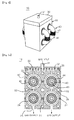
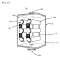
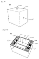
- the plasma reactor 10 comprises a reactor body 20 with a number of independent plasma discharge chambers 21.
- the reactor body 20 is connected to a transformer 40 for transferring an electromotive force for plasma discharge to the plasma discharge chamber 21.
- the transformer 40 includes a magnetic core 41 and a primary winding 42 which are positioned across the plasma discharge chamber 21.
- the magnetic core 41 which is positioned inside the plasma discharge chamber 21, is wound by a core protecting tube 45, to be protected on the whole.
- the primary winding 42 is electrically connected to a power supply source 60 for providing radio frequency power.
- the reactor body 20 has gas entrances 22 with a number of holes which are opened towards the two plasma discharge chambers 21 positioned at the upper position of the plasma reactor 10.
- the reactor body 20 further has gas exits 25 opened downward in the two plasma discharge chamber 21 positioned at the lower position of the plasma reactor 10.
- the reactor body 20 further has connection paths 23 with a number of holes which connect the plasma discharge chambers 21 at the upper and lower positions to each other.
- a gas distributor 30 may be set up at the upper position of the reactor body 20.
- the gas distributor 30 includes a gas entrance 31 connected to a gas supply source (not shown) and one or more gas distributing plates 32 to evenly distribute the gas.
- the gas flowing into the plasma discharge chamber 21 is selected from a group including an inert gas, a reaction gas, and a mixture of these. Alternatively, other gases suitable for other plasma processes may be selected.
- the reactor body 20 is vacuum-insulated by a vacuum-insulating member 44 at its part which is in contact with the core protecting tube 45.
- the reactor body 20 is made of metal material, for example, aluminum, stainless or copper.
- the reactor body 20 may be made of coated metal, for example, anodized aluminum, or aluminum coated with nickel.
- the reactor body 20 may be made of refractory metal.
- the reactor body 20 may be made of insulating material, such as quartz or ceramic or may be made of any other material that is suitable for performing an intentioned plasma process.
- one or more electrically insulating region 27 which has electrical discontinuity in the metal material is included to minimize the eddy current.
- the insulating region 27 may be formed to cross each plasma discharge chamber 21 as shown.
- the magnetic core 41 is shared in at least two plasma discharge chamber 21. A part of the magnetic core 41 is mounted so as to be externally exposed out of the reactor body 20.
- the magnetic core 41 is made of ferrite material but may be made of other materials, such as iron and air.
- the core protecting tube 45 is made of dielectric material, such as quartz or ceramic.
- the core protecting tube 45 may be made of the same metal material as that of the reactor body 20 described above.
- the core protecting tube 45 includes one or more electrically insulating region with the electrical discontinuity to prevent the eddy current.
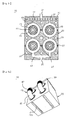
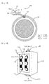
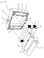
- FIG. 3 is an exploded perspective view illustrating the core protecting tube 45 and a cooling tube to be mounted in the magnetic core 42
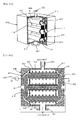
- FIGS. 4A and 4B are sectional views illustrating the magnetic core in which the core protecting tube and cooling tube are mounted.
- a cooling water supply conduit 44 for forming a cooling water supplying channel is mounted in the magnetic core 41.
- a cooling water supplying channel 43 may be formed through the center of the magnetic core 42.
- the cooling water supplying channel 43 may be formed the center of both the cooling water supply conduit 44 and the magnetic core 41.
- a number of cooling channels 26 may be formed in the reactor body 20.
- FIG. 4A is a sectional view illustrating the cooling water supplying channel 43 formed in the center of the magnetic core 41 and the cooling water supplying conduit 44 positioned inside of the core protecting tube 45.
- FIG. 4B is a sectional view the cooling water supplying conduit 44 only positioned.
- the cooling water supplying conduit 44 may be made of metal material and, in this case, the cooling water supplying conduit 44 may have an insulating region 48 to prevent the eddy current from being induced.
- a current of the primary winding 42 is driven by the power supply source 60.
- the driving current of the primary winding 42 induces AC potential inside the plasma discharge chamber 21 of forming inductively coupled plasma, to complete a secondary circuit of the transformer 50.
- the inductively coupled plasma is formed in each plasma discharge chamber 21, to cover the outside of the core protecting tube 45, focusing on a core cross sectional part.
- Reference numeral '46' indicates an induced electric field induced by the magnetic core 41
- reference numeral '47' indicates an electric field secondarily induced by the induced electric field 46.
- the power supply source 60 is constituted by using a RF power supply source which is capable of controlling an output voltage, without using any additional impedance matcher.
- the power supply source 60 may be constituted by using the RF power supply source which matches the impedance by an additional impedance matcher.
- the efficiency of transferring the inductively coupled energy which is connected with plasma is very high because a number of magnetic core cross sectional parts are positioned inside the plasma discharge chamber 21. Furthermore, since the plasma discharge chambers 21 are positioned in multistage arrangement, high density plasma is easily produced without excessively increasing radio frequency.
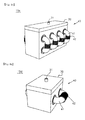
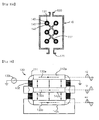
- FIGS. 5A through 5C are front sectional views illustrating various modified examples of the gas flow path
- FIGS. 6A and 6B are bottom perspective views illustrating examples of the gas exit.
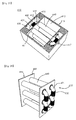
- FIG. 5A illustrates a modified example in which a gas collecting region 50 may be formed in the middle of four plasma discharge chambers 21.
- a plasma gas generated in the two plasma discharge chambers 21 positioned at the upper stage is collected in the gas collecting region 50 and then is dispersed and input into the plasma discharge chambers 21 positioned at the lower stage.
- FIG. 5B illustrates another modified example not forming part of the invention in which a gas collecting region 52 may be formed under the two plasma discharge chambers 21 positioned at the lower stage.
- the plasma gas generated in the two plasma discharge chambers 21 positioned at the lower stage is collected in the gas collecting region 52 and is output through one gas exit 25.
- FIG. 5C illustrates another modified example not forming part of the invention in which one gas exit 25 is formed and a gas exhaust path 54 is formed to be connected the two plasma discharge chambers 21 positioned at the lower stage.
- the gas exit 25 may be formed in a gas exit 25a in a slit shape which is long and narrowly opened under the reactor body 20 as illustrated in FIG. 6A .
- the gas exit 25 may be formed in a round gas exit 26b which includes a flange structure as illustrated in FIG. 6B .
- FIG. 7 is a view of an example in which the plasma reactor is mounted in a process chamber 70.
- the plasma reactor 10 is mounted in the process chamber 70 and remotely supplies plasma into the process chamber 70.
- the plasma reactor 10 may be mounted onto the outside of the ceiling of the process chamber 70.
- RF frequency is provided from a RF frequency generator 72 to the plasma reactor 10 and a gas is supplied from a gas supply system (not shown) into the plasma reactor 10 so that the plasma reactor 10 generates an active gas.
- the process chamber 70 receives the active gas generated in the plasma reactor 10 and performs a predetermined plasma process.
- the process chamber 70 may be, for example, a deposition chamber for performing a deposition process or an etching chamber for an etching process.
- the process chamber 70 may be an ashing chamber for stripping photoresist.
- the process chamber 70 may be a plasma process chamber for performing various processes for semiconductor fabrication.
- the plasma reactor 10 is separated, in structure, from the RF frequency generator 72 which is the power supply source for supplying the RF power. That is, the plasma reactor 10 is constituted to be fixedly mountable into the process chamber, and the RF frequency generator 72 is constituted to be separable from the plasma reactor 10. An output terminal of the RF frequency generator 72 is remotely connected to a RF frequency input terminal of the plasma reactor 10 by a RF frequency cable 74. Therefore, unlike a conventional art in which the RF frequency generator and the plasma reactor are constituted as one unit, in the present invention the RF frequency generator 72 and the plasma reactor 10 are very easily installed in the process chamber 70, thereby enhancing the efficiency of maintenance of the system.
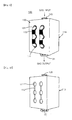
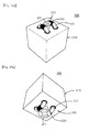
- FIGS. 8A through 8D are views illustrating modified examples of the reactor.
- two plasma discharge chambers are vertically positioned (in FIG. 8A ) or horizontally positioned (in FIG. 8D ), or a number of plasma discharge chambers are vertically positioned in parallel (in FIG. 8B ) or horizontally positioned in parallel (in FIG. 8C ).
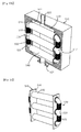
- FIG. 9 is a perspective view of a plasma reactor
- FIG. 10 is a perspective view illustrating the constitution of a reactor body of the plasma reactor of FIG. 9
- FIG 11 is a partial exploded perspective view illustrating an inside of the plasma reactor of FIG. 9 .
- the plasma reactor 100 comprises a reactor body 110 which forms a plasma discharge chamber 113 and includes a gas entrance 120 and a gas exit 121.
- a transformer 130 comprises a magnetic core 131 and a primary winding 132.
- the magnetic core 131 includes two or more core cross sectional parts which are across the inside of the plasma discharge chamber 113, and parts of the magnetic core 131 which are positioned outside the plasma discharge chamber 113.
- the primary winding 132 is wound around the magnetic core 131 and is electrically connected to a power supply source 133 (in FIG. 13 ).
- the power supply source 13 is constituted by using a RF power supply source which is capable of controlling an output voltage, without using any additional impedance matcher.
- the power supply source may be constituted by using a RF power supply source with an impedance matcher.
- a gas flowing into the plasma discharge chamber 113 is selected from a group of inert gas, reaction gas, and a mixture of these. Or any other gases suitable for other plasma processes may be selected as the gas flowing into the plasma discharge chamber 113.
- the reactor body 110 has a number of apertures 111 at which both ends of a single core protecting tube 140 are positioned. Contact parts of the single core protecting tube 140 and the apertures 111 are vacuum-insulated by a vacuum-insulating member 101 (in FIG. 13 ).
- the reactor body 110 is made of metal material, for example, aluminum, stainless or copper.
- the reactor body 10 may be made of coated metal, for example, anodized aluminum or aluminum coated with nickel.
- the reactor body 10 may be made of refractory metal.
- the reactor body 10 may be made of insulating material, such as quartz or ceramic or any other material suitable for performing an intentioned plasma process.
- the reactor body 110 When the reactor body 110 includes the metal material, it includes one or more electrically insulating region 112 to have the electrical discontinuity in the metal material, to minimize the eddy current.
- the electrically insulating layer 112 may be formed in various shapes as shown in FIGS. 15 through 15D .
- the parts of the magnetic core 131 are exposed to be mounted outside the sidewall of the reactor body 110.
- the magnetic core 131 is formed in an integrated multiple loop type, for example, two-stage multiple loops. However, the magnetic core 131 may use an independent single loop type.
- the magnetic core 131 may be made of ferrite material but, alternatively, may be made of other materials, such as iron and air.
- the two or more core cross sectional parts positioned inside the plasma discharge chamber 113 are protected by being covered by the core protecting tube 140 in a tube type.
- the core protecting tube 140 is independently mounted on each core cross sectional part.
- the core protecting tube 140 is made of dielectric material, such as quartz or ceramic.
- the core protecting tube 140 may be made of the same metal material as that of the reactor body 110 as described above, and, in this case, includes one or more electrically insulating regions to have the electrical discontinuity to prevent the eddy current.
- FIG. 12 is an exploded perspective view illustrating the constitution of the core protecting tube, a cooling tube and a capacitively coupled electrode 142 to be mounted in the magnetic core of FIG. 9 .
- a cooling water supplying conduit 14 for forming a cooling water supplying channel is mounted in the magnetic core 131.
- the cooling water supplying channel may be formed through the center of the magnetic core 131.
- the cooling water supplying channel may be formed in both the cooling water supplying conduit 141 and the center of the magnetic core 131.
- the cooling water supplying channel may be formed in the reactor body 110.
- the capacitively coupled electrode 142 is mounted in the magnetic core 131.
- the capacitively coupled electrode 142 is selectively mounted, and more detailed description thereof will be presented later.
- FIG. 13 is a sectional view of the plasma reactor for visually illustrating an electrical connection of the transformer and a magnetic field and an electric field induced by the electrical connection of the transformer.
- FIG. 14 is a sectional view of a multistage plasma discharge region of the plasma reactor.
- a current of the primary winding 132 is driven by the power supply source 133.
- the driving current of the primary winding 132 induces AC potential inside the plasma discharge chamber 113 which generates inductively coupled plasma to complete a secondary circuit of the transformer 130.
- the inductively coupled plasma is formed in a multistage type in the plasma discharge chamber 113, to cover the outside of the core protecting tube 140, focusing on the two or more core cross sectional parts.
- a gas flow path 153 is formed along the multistage plasma discharge regions PDR_1, PDR_2 and PDR_3.
- the two or more core cross sectional parts are positioned so as to be at right angles to the gas flow path 153 inside the plasma discharge chamber 113.
- the two or more core cross sectional parts may be positioned so as to be horizontally.
- FIG. 16 is a view for explaining a phase relation of a voltage induced to the capacitively coupled electrode.
- the capacitively coupled electrode 142 is wound about the core cross sectional parts a number of turns, thereby functioning as a secondary winding of the transformer 130. At least two or more capacitively coupled electrodes 142a, 142b and 142c are capacitively coupled by inverse voltages V+ and V- which are induced therebetween.
- a number of primary windings 132 are wound about the three core cross sectional parts in a proper direction, so that adjacent core cross sectional parts induce electric fields 133a, 133b and 133c which are opposite to one another. Therefore, the three capacitively coupled electrodes 142a, 142b and 142c induce the mutual inverse voltages V+ and V-.
- FIG. 17 is a view illustrating the constitution of an induction voltage controlling circuit of the capacitively coupled electrode.
- the induction voltage controlling circuit 150 comprises a switching circuit 151 for varying the number of winding by switching a multi tap 151 and a multi tap to vary the number of winding of the capacitively coupled electrode 142.
- the number of winding is varied as the switching circuit 151 is switched.
- the level of a voltage induced to the capacitively coupled electrode 142 is varied as the number of winding is varied.
- the efficiency of transferring the inductively coupled energy to be connected with plasma is very high because a number of magnetic core cross sectional parts are positioned inside the plasma discharge chamber 113.
- the capacitively coupled electrode 142 is constituted to additionally provide the variable capacitively coupled energy to be connected with plasma, the plasma is stably maintained and the plasma ion density and ion energy are easily controlled.
- the capacitively coupled electrode 142 may be selectively used only when igniting plasma at the beginning of driving the plasma reactor 100 or may be used to control the plasma ion density and ion temperature after the plasma ignition.
- FIG. 18 is a perspective view of a plasma reactor
- FIG. 19 is a perspective view illustrating a structure of a reactor body of the plasma reactor of FIG. 18
- FIG. 20 is a perspective view illustrating an integrated multiple core protecting tube of FIG. 18
- FIG. 21 is sectional view of the plasma reactor for illustrating a structure of mounting the core protecting tube.
- the plasma reactor 100 may comprise the integrated multiple core protecting tube 145.
- both ends of the core protecting tube 140 are formed in one body by a structure of each flange 144.
- the reactor body 110' includes an aperture 111' suitable shape for mounting the flange 144 of the multi core protecting tube 145.
- the reactor body 110' further includes a vacuum-insulating member 102 for vacuum-insulating a contact part of the flange 144 of the multiple core protecting tube 145 and the aperture 111'.
- FIGS. 22 , 23A and 23B are perspective views of plasma reactors according to other modified examples as alternative plans.
- a plasma reactor 200 according to another modified example comprises a transformer 230 with a magnetic core 231 using a single loop and a primary winding 232.
- the magnetic core 231 is vertically mounted in a gas path formed between a gas entrance 220 and a gas exit 221.
- a plasma reactor 300 according to another modified example comprises a transformer 330 with a magnetic core 331 and a primary winding 332.
- the magnetic core 331 is mounted in parallel to a gas flow path formed between a gas entrance 320 and a gas exit 321.
- FIG. 24 is a bottom perspective view of a plasma reactor with multiple gas exits.
- the plasma reactor 100 may has two or more separated multiple gas exits 121a, 121b, 121c and 121d.
- the multiple gas exits 121a and 121d are effectively used for broadly and uniformly supplying plasma in a large area during a plasma process with large volume.
- FIG. 25 is a perspective view of a plasma reactor 400 according to another modified example, in which a magnetic core is mounted onto a sidewall of a reactor body.
- FIGS. 26A through 26D are views illustrating an internal structure of the plasma reactor of FIG. 25 .
- the plasma reactor 400 has the same constitution as described above. Therefore, no further description of the same constitution will be presented.
- the plasma reactor 400 is characterized in that a reactor body 410 comprises a sidewall chamber 415 for receiving parts of a magnetic core 131.
- a magnetic core 131 of a transformer 430 has its part being mounted in the sidewall chamber 415 of the reactor body 410.
- the reactor body 410 has an aperture 417 externally opened to the sidewall chamber 415. The aperture 417 is used as a path for supplying a primary winding 432 and cooling water.
- one or more insulating regions 412 to minimize the eddy current are properly formed in a sidewall 414 formed between the sidewall chamber 415 and a plasma reaction chamber 413.
- a core protecting tube 440 is independently mounted for each core cross sectional part.
- the sidewall 414 includes a number of apertures 411 for mounting the core protection tubes 440. Contact parts between two or more core protecting tubes 440 and a number of apertures 411 are vacuum-insulated by a vacuum-insulating member 402.
- the core protecting tube 440, a cooling water supplying conduit 441 and a capacitively coupled electrode 442 are mounted in a magnetic core 431, as shown in FIG. 26D .
- the magnetic core 431 with multiple routes is positioned in parallel, so that the core cross sectional part is vertically across between a gas entrance 420 and a gas exit 421.
- a number of magnetic cores 431 with a single loop are stacked in parallel as illustrated in FIG. 27 .
- the plasma reactor 400 may include an integrated multiple-core protecting tube 445 with a common flange 444.
- a reactor body 410 is constituted as described above, with respect to appropriate modification and vacuum-insulation according to the multiple-core protecting tube 445.
- FIG. 29 is a perspective view of a plasma reactor according to another modified example
- FIGS. 30A and 30B are sectional perspective views of the plasma reactor of Fig. 29 .
- the plasma reactor 500 comprises a transformer 530 with a magnetic core 531 with multiple loops and a primary winding. This modification may be equally applicable to the above-described embodiment and examples.
- each independent core protecting tube 540 is used and a multiple-core protecting tube 545 with a common flange 544 may be used as illustrated in FIG. 31 . Since the specific constitution and operation of the modified example of FIG. 29 , except for these alternatively modifications, are same as those of the above-described modified examples, no detailed description thereof will be presented.
- FIG. 32 is a view illustrating an example in which the plasma reactor is mounted in a process chamber.
- the plasma reactor 100 remotely supplies plasma to the process chamber 600.
- the plasma reactor 100 may be positioned outside the ceiling of the process chamber 600.
- the plasma reactor 100 receives radio frequency from a radio frequency generator 610 which is a power supply source and receives a gas by a gas supplying system (not shown), thereby generating an active gas.
- the process chamber 600 performs a predetermined plasma process by receiving the active gas generated in the plasma reactor 100.
- the process chamber 600 may be, for example, a deposition chamber for performing a deposition process or an etching chamber for performing an etching process.
- the process chamber 600 may be an ashing chamber for stripping photoresist.
- the process chamber 600 may be a plasma processing chamber for performing various semiconductor fabrication processes.
- the plasma reactor 100 and the radio frequency generator 610 are separated in structure. That is, the plasma reactor 100 is constituted to be fixedly mounted in the process chamber 600, and the radio frequency generator 610 is separable from the plasma reactor 100. An output terminal of the radio frequency generator 610 is remotely connected to a radio frequency input terminal of the plasma reactor 100 by a radio frequency cable 620. Therefore, unlike the conventional art in which the radio frequency generator and the plasma reactor are constituted in one unit, the plasma reactor 100 is very easily positioned in the process chamber 600 and the efficiency of maintenance of the system is enhanced.
- FIG. 33 is a view for explaining an inductively coupled plasma reactor 100 formed in one body on a process chamber 700.
- the plasma reactor 100 may be combined with the process chamber 700 in one body.
- the plasma reactor 100 is positioned on the ceiling opposite to a substrate supporting stage 701 positioned inside the process chamber 700.
- the bottom of the plasma reactor 100 has an entirely opened structure 121' towards the substrate supporting stage 701.
- An active gas generated in the plasma reactor 100 flows into an inner region 703 of the process chamber 700.
- the substrate supporting stage 701 is connected to a bias power source (not shown) so that active gas ions are accelerated towards a substrate 702.
- the efficiency of transferring the inductively coupled energy to be connected with plasma is very high. Furthermore, since a number of plasma discharge chambers are positioned in multistage arrangement, high density plasma is easily produced, without excessively increasing the radio frequency power. Furthermore, when the capacitively coupled electrode is included, since the variable capacitively coupled energy to be connected with plasma is additionally provided, the plasma is stably maintained and the plasma ion density and ion energy are easily controlled.
Landscapes
- Physics & Mathematics (AREA)
- Engineering & Computer Science (AREA)
- Plasma & Fusion (AREA)
- Chemical & Material Sciences (AREA)
- Analytical Chemistry (AREA)
- Plasma Technology (AREA)
- Chemical Vapour Deposition (AREA)
- Drying Of Semiconductors (AREA)
Claims (14)
- Induktiv gekoppelter Plasmareaktor (10), umfassend:einen Reaktorkörper (20), der eine Vielzahl von Plasmaentladungskammern (21) aufweist, die in mehrstufiger Anordnung und parallel positioniert sind, wobei der Reaktorkörper (20) Gaseinlässe (22) mit einer Anzahl von Löchern aufweist, die gegen die oberen Plasmaentladungskammern (2) geöffnet sind, welche in einer oberen Stellung des Plasmareaktors positioniert sind;einen Transformator (40), der einen magnetischen Kern (41) und eine Primärwicklung (42) umfasst, wobei der magnetische Kern (41) zwischen zumindest zwei Plasmaentladungskammern (21) geteilt wird und durch jede der Plasmaentladungskammern (21) positioniert ist, wobei Teile des magnetischen Kerns (41) so montiert sind, dass sie außerhalb des Reaktorkörpers (20) äußerlich exponiert sind;ein Kernschutzrohr (45), das so angeordnet ist, um Teile des magnetischen Kerns (41) abzudecken und zu schützen, die innerhalb jeder der Plasmaentladungskammern (21) positioniert sind; undeine Stromversorgungsquelle (60), die mit der Primärwicklung (42) verbunden ist, undworin ein Strom der Primärwicklung (42) von der Stromversorgungsquelle (60) getrieben ist, der Antriebsstrom der Primärwicklung (42) ein WS-Potential induziert, welches induktiv gekoppeltes Plasma erzeugt, um einen Sekundärstromkreis des Transformators (40) zu vervollständigen, und wobei das induktiv gekoppelte Plasma in jeder von der Vielzahl der Plasmaentladungskammern (21) erzeugt wird, um die äußere Seite des Kernschutzrohrs (45) abzudecken,und worin der Reaktorkörper (20) ferner mehrfache Gasauslässe (25) umfasst, welche in den unteren Plasmaentladungskammern (21) nach unten geöffnet sind, welche in einer unteren Stellung des Plasmareaktors positioniert sind, wobei der Reaktorkörper (20) ferner Verbindungswege (23) mit einer Anzahl von Löchern aufweist, die die Plasmaentladungskammern (21) an den oberen und unteren Stellungen miteinander verbinden, wobei ein Gasströmungsweg, der durch eine Anzahl der Plasmaentladungskammern (21) fließt, zwischen den Gaseinlässen (22) und den Gasauslässen (25) gebildet wird.
- Induktiv gekoppelter Plasmareaktor nach Anspruch 1, worin der Reaktorkörper (20) ein Gassammelgebiet (52) umfasst, das mit zumindest zwei Kammerverbindungswegen (23) verbunden ist.
- Induktiv gekoppelter Plasmareaktor nach Anspruch 1, worin der Reaktorkörper (20) einen Gasverteiler (30) zur gleichmäßigen Verteilung und Zufuhr eines Gases zum Gaseinlass (22) umfasst.
- Induktiv gekoppelter Plasmareaktor nach Anspruch 1, worin der Reaktorkörper (20) aus einem Metallmaterial besteht und das Metallmaterial ein oder mehrere elektrisch isolierende Gebiete (27) einschließt, um eine elektrische Diskontinuität im Metallmaterial zu erzielen, um einen Wirbelstrom zu minimieren.
- Induktiv gekoppelter Plasmareaktor nach Anspruch 1, worin das Kernschutzrohr (45) aus einem Dielektrikum besteht.
- Induktiv gekoppelter Plasmareaktor nach Anspruch 1, worin das Kernschutzrohr (45) ein Metallmaterial umfasst und das Metallmaterial ein oder mehrere elektrisch isolierende Gebiete einschließt, um eine elektrische Diskontinuität im Metallmaterial zu erzielen, um den Wirbelstrom zu minimieren.
- Induktiv gekoppelter Plasmareaktor nach Anspruch 1, ferner umfassend: einen Kühlwasserzufuhrkanal (43), der innerhalb des Kernschutzrohrs (45) positioniert ist.
- Induktiv gekoppelter Plasmareaktor nach Anspruch 7, worin der Kühlwasserzufuhrkanal (43) ein Metallmaterial umfasst und das Metallmaterial ein oder mehrere elektrisch isolierende Gebiete (48) einschließt, um eine elektrische Diskontinuität im Metallmaterial zu erzielen, um den Wirbelstrom zu minimieren.
- Induktiv gekoppelter Plasmareaktor nach Anspruch 1, ferner umfassend: einen Kühlwasserzufuhrkanal (43), der durch die Mitte des magnetischen Kerns (41) geformt ist.
- Induktiv gekoppelter Plasmareaktor nach Anspruch 1, ferner umfassend: einen Impedanzanpasser, der eine Impedanzanpassung durchführt, wobei der Impedanzanpasser zwischen der Stromversorgungsquelle (60) und der Primärwicklung (42) geformt ist.
- Induktiv gekoppelter Plasmareaktor nach Anspruch 1, worin die Stromversorgungsquelle (60) ohne jeden einstellbaren Anpasser betrieben wird.
- Induktiv gekoppelter Plasmareaktor nach Anspruch 1, ferner umfassend: eine Verarbeitungskammer (70) zur Aufnahme und zur Lagerung eines Plasmagases, das im Reaktorkörper (20) erzeugt wird.
- Induktiv gekoppelter Plasmareaktor nach Anspruch 12, worin der Reaktorkörper (20) eine Struktur aufweist, die an der Verarbeitungskammer (70) montiert werden soll, die Stromversorgungsquelle (60) eine Struktur aufweist, die vom Reaktorkörper (20) körperlich getrennt werden soll, und die Stromversorgungsquelle (60) und der Reaktorkörper (20) durch ein Stromanschlusskabel (74) aus der Ferne verbunden sind.
- Induktiv gekoppelter Plasmareaktor nach Anspruch 1, worin das Gas, das in die Plasmaentladungskammern (21) hinein fließt, aus einer Gruppe gewählt ist, die aus einem Inertgas, aus einem Reaktionsgas und aus einer Mischung derselben besteht.
Applications Claiming Priority (2)
| Application Number | Priority Date | Filing Date | Title |
|---|---|---|---|
| KR1020060036879A KR100793457B1 (ko) | 2006-04-24 | 2006-04-24 | 다중 방전실을 갖는 플라즈마 반응기 |
| KR1020060036490A KR100805557B1 (ko) | 2006-04-24 | 2006-04-24 | 다중 마그네틱 코어가 결합된 유도 결합 플라즈마 소스 |
Publications (2)
| Publication Number | Publication Date |
|---|---|
| EP1850367A1 EP1850367A1 (de) | 2007-10-31 |
| EP1850367B1 true EP1850367B1 (de) | 2015-10-21 |
Family
ID=38291037
Family Applications (1)
| Application Number | Title | Priority Date | Filing Date |
|---|---|---|---|
| EP07106861.3A Not-in-force EP1850367B1 (de) | 2006-04-24 | 2007-04-24 | Induktiv gekoppelter Plasmareaktor mit mehreren Magnetkernen |
Country Status (4)
| Country | Link |
|---|---|
| US (2) | US8597464B2 (de) |
| EP (1) | EP1850367B1 (de) |
| JP (1) | JP5257917B2 (de) |
| TW (1) | TWI418261B (de) |
Families Citing this family (24)
| Publication number | Priority date | Publication date | Assignee | Title |
|---|---|---|---|---|
| US9275839B2 (en) * | 2007-10-19 | 2016-03-01 | Mks Instruments, Inc. | Toroidal plasma chamber for high gas flow rate process |
| KR101021480B1 (ko) * | 2007-12-07 | 2011-03-16 | 성균관대학교산학협력단 | 페라이트 구조체를 구비하는 플라즈마 소스 및 이를채택하는 플라즈마 발생장치 |
| KR100999182B1 (ko) * | 2008-05-20 | 2010-12-08 | 주식회사 뉴파워 프라즈마 | 내장 변압기를 갖는 플라즈마 반응기 |
| US8742665B2 (en) * | 2009-11-18 | 2014-06-03 | Applied Materials, Inc. | Plasma source design |
| KR101364578B1 (ko) * | 2012-01-10 | 2014-02-18 | 최대규 | 하이브리드 플라즈마 반응기 |
| US10115565B2 (en) | 2012-03-02 | 2018-10-30 | Panasonic Intellectual Property Management Co., Ltd. | Plasma processing apparatus and plasma processing method |
| JP5899422B2 (ja) * | 2012-09-18 | 2016-04-06 | パナソニックIpマネジメント株式会社 | 誘導結合型プラズマ処理装置及び方法 |
| WO2014045547A1 (ja) * | 2012-09-18 | 2014-03-27 | パナソニック株式会社 | プラズマ処理装置及びプラズマ処理方法 |
| JP6074668B2 (ja) * | 2013-03-28 | 2017-02-08 | パナソニックIpマネジメント株式会社 | プラズマ処理装置及び方法 |
| KR102376982B1 (ko) * | 2015-04-14 | 2022-03-21 | 삼성전자주식회사 | 세라믹을 이용하여 파티클 저감 효과를 가지는 원격 플라즈마 발생장치 |
| EP3432691B1 (de) * | 2016-03-14 | 2020-06-24 | Fuji Corporation | Plasmagenerator |
| KR102586129B1 (ko) * | 2016-06-29 | 2023-10-10 | 주식회사 뉴파워 프라즈마 | 가스 분해를 위한 구조를 구비한 플라즈마 반응기 |
| JP6688199B2 (ja) * | 2016-09-30 | 2020-04-28 | 株式会社ダイヘン | プラズマ発生装置 |
| KR102697703B1 (ko) | 2018-06-14 | 2024-08-23 | 엠케이에스 인스트루먼츠 인코포레이티드 | 원격 플라즈마 공급원을 위한 라디칼 출력 모니터 및 사용 방법 |
| WO2020226086A1 (ja) * | 2019-05-08 | 2020-11-12 | 株式会社クメタ製作所 | プラズマ生成装置 |
| JP6782952B1 (ja) * | 2019-05-08 | 2020-11-11 | 株式会社クメタ製作所 | プラズマ生成装置 |
| WO2021113496A1 (en) | 2019-12-03 | 2021-06-10 | Thrivaltech, Llc | Induction feed through system |
| KR102942937B1 (ko) * | 2020-06-16 | 2026-03-25 | 주식회사 뉴파워 프라즈마 | 플라즈마 반응 장치 및 이의 냉각 방법 |
| KR102897317B1 (ko) * | 2020-06-16 | 2025-12-11 | 주식회사 뉴파워 프라즈마 | 플라즈마 반응 장치 |
| JP2022007611A (ja) * | 2020-06-26 | 2022-01-13 | 東京エレクトロン株式会社 | プラズマを形成する装置、基板を処理する装置、及びプラズマを形成する方法 |
| KR102856977B1 (ko) * | 2023-05-22 | 2025-09-09 | 한국기계연구원 | 트랩형 플라즈마 반응장치 및 이를 구비한 반도체 공정 설비 |
| KR102881065B1 (ko) * | 2023-06-26 | 2025-11-05 | 한국기계연구원 | 플라즈마 반응장치, 이를 이용한 공정가스 처리 방법, 및 이를 구비한 반도체 공정 설비 |
| KR102881066B1 (ko) * | 2023-07-18 | 2025-11-05 | 한국기계연구원 | 플라즈마 반응장치, 이를 이용한 공정가스 처리 방법, 및 이를 구비한 반도체 공정 설비 |
| CN120779181B (zh) * | 2025-08-13 | 2026-03-17 | 武汉武高电测电气有限公司 | 一种串联谐振实验装置 |
Citations (1)
| Publication number | Priority date | Publication date | Assignee | Title |
|---|---|---|---|---|
| EP0908923A2 (de) * | 1997-10-10 | 1999-04-14 | European Community | Verfahren und Vorrichtung zur Erzeugung eines ausgedehnten Induktionsplasmas für Plasmabehandlungen |
Family Cites Families (19)
| Publication number | Priority date | Publication date | Assignee | Title |
|---|---|---|---|---|
| US3406241A (en) * | 1967-03-10 | 1968-10-15 | Northwestern Steel & Wire Co | Method and apparatus for balancing the arc power of a direct arc electric furnace and protecting the refractory lining in the hot spots of the furnace |
| US4431898A (en) * | 1981-09-01 | 1984-02-14 | The Perkin-Elmer Corporation | Inductively coupled discharge for plasma etching and resist stripping |
| US5290382A (en) * | 1991-12-13 | 1994-03-01 | Hughes Aircraft Company | Methods and apparatus for generating a plasma for "downstream" rapid shaping of surfaces of substrates and films |
| JPH09180897A (ja) * | 1995-12-12 | 1997-07-11 | Applied Materials Inc | 高密度プラズマリアクタのためのガス供給装置 |
| JP3279919B2 (ja) * | 1996-05-14 | 2002-04-30 | 東京応化工業株式会社 | 同時放電化装置 |
| US6150628A (en) * | 1997-06-26 | 2000-11-21 | Applied Science And Technology, Inc. | Toroidal low-field reactive gas source |
| US6203657B1 (en) * | 1998-03-31 | 2001-03-20 | Lam Research Corporation | Inductively coupled plasma downstream strip module |
| US5998933A (en) * | 1998-04-06 | 1999-12-07 | Shun'ko; Evgeny V. | RF plasma inductor with closed ferrite core |
| US6392351B1 (en) * | 1999-05-03 | 2002-05-21 | Evgeny V. Shun'ko | Inductive RF plasma source with external discharge bridge |
| KR20020029743A (ko) * | 1999-08-06 | 2002-04-19 | 로버트 엠. 포터 | 가스와 재료를 처리하기 위한 유도결합 링-플라즈마소스장치 및 그의 방법 |
| US6418874B1 (en) * | 2000-05-25 | 2002-07-16 | Applied Materials, Inc. | Toroidal plasma source for plasma processing |
| EP1307896A2 (de) * | 2000-08-11 | 2003-05-07 | Applied Materials, Inc. | Von aussen angeregte torroidförmige plasmaquelle |
| US6348126B1 (en) * | 2000-08-11 | 2002-02-19 | Applied Materials, Inc. | Externally excited torroidal plasma source |
| US6755150B2 (en) * | 2001-04-20 | 2004-06-29 | Applied Materials Inc. | Multi-core transformer plasma source |
| US20030015965A1 (en) * | 2002-08-15 | 2003-01-23 | Valery Godyak | Inductively coupled plasma reactor |
| KR100488348B1 (ko) * | 2002-11-14 | 2005-05-10 | 최대규 | 플라즈마 프로세스 챔버 및 시스템 |
| US6724148B1 (en) * | 2003-01-31 | 2004-04-20 | Advanced Energy Industries, Inc. | Mechanism for minimizing ion bombardment energy in a plasma chamber |
| US8409400B2 (en) * | 2003-05-07 | 2013-04-02 | Gen Co., Ltd. | Inductive plasma chamber having multi discharge tube bridge |
| ATE543199T1 (de) * | 2005-05-23 | 2012-02-15 | New Power Plasma Co Ltd | Plasmakammer mit entladung induzierender brücke |
-
2007
- 2007-03-01 JP JP2007051634A patent/JP5257917B2/ja not_active Expired - Fee Related
- 2007-04-19 US US11/737,648 patent/US8597464B2/en not_active Ceased
- 2007-04-24 EP EP07106861.3A patent/EP1850367B1/de not_active Not-in-force
- 2007-04-24 TW TW096114465A patent/TWI418261B/zh not_active IP Right Cessation
-
2014
- 2014-05-06 US US14/270,911 patent/USRE45527E1/en not_active Expired - Fee Related
Patent Citations (1)
| Publication number | Priority date | Publication date | Assignee | Title |
|---|---|---|---|---|
| EP0908923A2 (de) * | 1997-10-10 | 1999-04-14 | European Community | Verfahren und Vorrichtung zur Erzeugung eines ausgedehnten Induktionsplasmas für Plasmabehandlungen |
Also Published As
| Publication number | Publication date |
|---|---|
| USRE45527E1 (en) | 2015-05-26 |
| US8597464B2 (en) | 2013-12-03 |
| TWI418261B (zh) | 2013-12-01 |
| TW200818997A (en) | 2008-04-16 |
| JP5257917B2 (ja) | 2013-08-07 |
| EP1850367A1 (de) | 2007-10-31 |
| JP2007294414A (ja) | 2007-11-08 |
| US20070245963A1 (en) | 2007-10-25 |
Similar Documents
| Publication | Publication Date | Title |
|---|---|---|
| EP1850367B1 (de) | Induktiv gekoppelter Plasmareaktor mit mehreren Magnetkernen | |
| EP1727186B1 (de) | Plasmakammer mit Entladung induzierender Brücke | |
| CN101064986B (zh) | 结合有多重磁芯的电感耦合等离子体反应器 | |
| KR101155840B1 (ko) | 플라즈마 처리 장치 및 방법 | |
| KR101296717B1 (ko) | 다중 경로 유도 결합 플라즈마 반응기 | |
| KR100803794B1 (ko) | 마그네틱 코어 블록에 매설된 플라즈마 방전 튜브를 구비한유도 결합 플라즈마 소스 | |
| TWI398926B (zh) | 具有與磁通通道耦合之電漿室的電漿反應器 | |
| KR20090073327A (ko) | 고밀도 원격 플라즈마 처리 장치 | |
| KR20090013626A (ko) | 다중 무선 주파수 안테나를 갖는 유도 결합 플라즈마반응기 | |
| KR101336796B1 (ko) | 다중방전관을 갖는 플라즈마 반응기 | |
| KR100793457B1 (ko) | 다중 방전실을 갖는 플라즈마 반응기 | |
| KR100743842B1 (ko) | 자속 채널에 결합된 플라즈마 챔버를 구비한 플라즈마반응기 | |
| KR100772447B1 (ko) | 내장 마그네틱 코어를 갖는 유도 결합 플라즈마 소스 | |
| KR101446185B1 (ko) | 고효율 유도 결합 플라즈마 반응기 | |
| KR100772451B1 (ko) | 플라즈마 처리 챔버 및 플라즈마 처리 시스템 | |
| EP2844042A1 (de) | Plasmareaktor und plasmazündverfahren damit | |
| KR100805558B1 (ko) | 마그네틱 코어에 결합된 다중 방전 튜브를 구비한 유도 결합 플라즈마 소스 | |
| KR100845912B1 (ko) | 다중 루프 코어 플라즈마 발생기 및 이를 구비한 플라즈마반응기 | |
| KR100845903B1 (ko) | 다중 코어 플라즈마 발생기를 갖는 플라즈마 반응기 | |
| KR20090071037A (ko) | 멀티 레이저 스캐닝 라인을 갖는 유도 결합 플라즈마반응기 | |
| TW202614135A (zh) | 遠端電漿源 | |
| KR101437861B1 (ko) | 자속 채널에 결합된 플라즈마 챔버를 구비한 고효율플라즈마 반응기 | |
| KR20090069346A (ko) | 멀티 레이저 스캐닝 라인을 갖는 다중 루프 코어 플라즈마반응기 | |
| KR20100100226A (ko) | 혼합형 플라즈마 반응기 |
Legal Events
| Date | Code | Title | Description |
|---|---|---|---|
| PUAI | Public reference made under article 153(3) epc to a published international application that has entered the european phase |
Free format text: ORIGINAL CODE: 0009012 |
|
| 17P | Request for examination filed |
Effective date: 20070502 |
|
| AK | Designated contracting states |
Kind code of ref document: A1 Designated state(s): AT BE BG CH CY CZ DE DK EE ES FI FR GB GR HU IE IS IT LI LT LU LV MC MT NL PL PT RO SE SI SK TR |
|
| AX | Request for extension of the european patent |
Extension state: AL BA HR MK YU |
|
| AKX | Designation fees paid |
Designated state(s): AT BE BG CH CY CZ DE DK EE ES FI FR GB GR HU IE IS IT LI LT LU LV MC MT NL PL PT RO SE SI SK TR |
|
| 17Q | First examination report despatched |
Effective date: 20080619 |
|
| RAP1 | Party data changed (applicant data changed or rights of an application transferred) |
Owner name: GEN CO., LTD. |
|
| GRAP | Despatch of communication of intention to grant a patent |
Free format text: ORIGINAL CODE: EPIDOSNIGR1 |
|
| INTG | Intention to grant announced |
Effective date: 20150506 |
|
| GRAS | Grant fee paid |
Free format text: ORIGINAL CODE: EPIDOSNIGR3 |
|
| GRAA | (expected) grant |
Free format text: ORIGINAL CODE: 0009210 |
|
| AK | Designated contracting states |
Kind code of ref document: B1 Designated state(s): AT BE BG CH CY CZ DE DK EE ES FI FR GB GR HU IE IS IT LI LT LU LV MC MT NL PL PT RO SE SI SK TR |
|
| RAP1 | Party data changed (applicant data changed or rights of an application transferred) |
Owner name: GEN CO., LTD. |
|
| REG | Reference to a national code |
Ref country code: GB Ref legal event code: FG4D Ref country code: NL Ref legal event code: MP Effective date: 20151021 |
|
| RIN1 | Information on inventor provided before grant (corrected) |
Inventor name: CHOI, DAE-KYU |
|
| REG | Reference to a national code |
Ref country code: CH Ref legal event code: EP |
|
| REG | Reference to a national code |
Ref country code: AT Ref legal event code: REF Ref document number: 757072 Country of ref document: AT Kind code of ref document: T Effective date: 20151115 |
|
| REG | Reference to a national code |
Ref country code: IE Ref legal event code: FG4D |
|
| REG | Reference to a national code |
Ref country code: DE Ref legal event code: R096 Ref document number: 602007043553 Country of ref document: DE |
|
| REG | Reference to a national code |
Ref country code: LT Ref legal event code: MG4D |
|
| REG | Reference to a national code |
Ref country code: AT Ref legal event code: MK05 Ref document number: 757072 Country of ref document: AT Kind code of ref document: T Effective date: 20151021 |
|
| PG25 | Lapsed in a contracting state [announced via postgrant information from national office to epo] |
Ref country code: ES Free format text: LAPSE BECAUSE OF FAILURE TO SUBMIT A TRANSLATION OF THE DESCRIPTION OR TO PAY THE FEE WITHIN THE PRESCRIBED TIME-LIMIT Effective date: 20151021 Ref country code: NL Free format text: LAPSE BECAUSE OF FAILURE TO SUBMIT A TRANSLATION OF THE DESCRIPTION OR TO PAY THE FEE WITHIN THE PRESCRIBED TIME-LIMIT Effective date: 20151021 Ref country code: LT Free format text: LAPSE BECAUSE OF FAILURE TO SUBMIT A TRANSLATION OF THE DESCRIPTION OR TO PAY THE FEE WITHIN THE PRESCRIBED TIME-LIMIT Effective date: 20151021 Ref country code: IS Free format text: LAPSE BECAUSE OF FAILURE TO SUBMIT A TRANSLATION OF THE DESCRIPTION OR TO PAY THE FEE WITHIN THE PRESCRIBED TIME-LIMIT Effective date: 20160221 Ref country code: IT Free format text: LAPSE BECAUSE OF FAILURE TO SUBMIT A TRANSLATION OF THE DESCRIPTION OR TO PAY THE FEE WITHIN THE PRESCRIBED TIME-LIMIT Effective date: 20151021 |
|
| PG25 | Lapsed in a contracting state [announced via postgrant information from national office to epo] |
Ref country code: SE Free format text: LAPSE BECAUSE OF FAILURE TO SUBMIT A TRANSLATION OF THE DESCRIPTION OR TO PAY THE FEE WITHIN THE PRESCRIBED TIME-LIMIT Effective date: 20151021 Ref country code: FI Free format text: LAPSE BECAUSE OF FAILURE TO SUBMIT A TRANSLATION OF THE DESCRIPTION OR TO PAY THE FEE WITHIN THE PRESCRIBED TIME-LIMIT Effective date: 20151021 Ref country code: PT Free format text: LAPSE BECAUSE OF FAILURE TO SUBMIT A TRANSLATION OF THE DESCRIPTION OR TO PAY THE FEE WITHIN THE PRESCRIBED TIME-LIMIT Effective date: 20160222 Ref country code: LV Free format text: LAPSE BECAUSE OF FAILURE TO SUBMIT A TRANSLATION OF THE DESCRIPTION OR TO PAY THE FEE WITHIN THE PRESCRIBED TIME-LIMIT Effective date: 20151021 Ref country code: PL Free format text: LAPSE BECAUSE OF FAILURE TO SUBMIT A TRANSLATION OF THE DESCRIPTION OR TO PAY THE FEE WITHIN THE PRESCRIBED TIME-LIMIT Effective date: 20151021 Ref country code: GR Free format text: LAPSE BECAUSE OF FAILURE TO SUBMIT A TRANSLATION OF THE DESCRIPTION OR TO PAY THE FEE WITHIN THE PRESCRIBED TIME-LIMIT Effective date: 20160122 Ref country code: AT Free format text: LAPSE BECAUSE OF FAILURE TO SUBMIT A TRANSLATION OF THE DESCRIPTION OR TO PAY THE FEE WITHIN THE PRESCRIBED TIME-LIMIT Effective date: 20151021 |
|
| REG | Reference to a national code |
Ref country code: DE Ref legal event code: R097 Ref document number: 602007043553 Country of ref document: DE |
|
| PG25 | Lapsed in a contracting state [announced via postgrant information from national office to epo] |
Ref country code: CZ Free format text: LAPSE BECAUSE OF FAILURE TO SUBMIT A TRANSLATION OF THE DESCRIPTION OR TO PAY THE FEE WITHIN THE PRESCRIBED TIME-LIMIT Effective date: 20151021 |
|
| PLBE | No opposition filed within time limit |
Free format text: ORIGINAL CODE: 0009261 |
|
| STAA | Information on the status of an ep patent application or granted ep patent |
Free format text: STATUS: NO OPPOSITION FILED WITHIN TIME LIMIT |
|
| PG25 | Lapsed in a contracting state [announced via postgrant information from national office to epo] |
Ref country code: DK Free format text: LAPSE BECAUSE OF FAILURE TO SUBMIT A TRANSLATION OF THE DESCRIPTION OR TO PAY THE FEE WITHIN THE PRESCRIBED TIME-LIMIT Effective date: 20151021 Ref country code: BE Free format text: LAPSE BECAUSE OF NON-PAYMENT OF DUE FEES Effective date: 20160430 Ref country code: EE Free format text: LAPSE BECAUSE OF FAILURE TO SUBMIT A TRANSLATION OF THE DESCRIPTION OR TO PAY THE FEE WITHIN THE PRESCRIBED TIME-LIMIT Effective date: 20151021 Ref country code: SK Free format text: LAPSE BECAUSE OF FAILURE TO SUBMIT A TRANSLATION OF THE DESCRIPTION OR TO PAY THE FEE WITHIN THE PRESCRIBED TIME-LIMIT Effective date: 20151021 Ref country code: RO Free format text: LAPSE BECAUSE OF FAILURE TO SUBMIT A TRANSLATION OF THE DESCRIPTION OR TO PAY THE FEE WITHIN THE PRESCRIBED TIME-LIMIT Effective date: 20151021 |
|
| 26N | No opposition filed |
Effective date: 20160722 |
|
| REG | Reference to a national code |
Ref country code: DE Ref legal event code: R119 Ref document number: 602007043553 Country of ref document: DE |
|
| PG25 | Lapsed in a contracting state [announced via postgrant information from national office to epo] |
Ref country code: SI Free format text: LAPSE BECAUSE OF FAILURE TO SUBMIT A TRANSLATION OF THE DESCRIPTION OR TO PAY THE FEE WITHIN THE PRESCRIBED TIME-LIMIT Effective date: 20151021 |
|
| REG | Reference to a national code |
Ref country code: CH Ref legal event code: PL |
|
| GBPC | Gb: european patent ceased through non-payment of renewal fee |
Effective date: 20160424 |
|
| PG25 | Lapsed in a contracting state [announced via postgrant information from national office to epo] |
Ref country code: BE Free format text: LAPSE BECAUSE OF FAILURE TO SUBMIT A TRANSLATION OF THE DESCRIPTION OR TO PAY THE FEE WITHIN THE PRESCRIBED TIME-LIMIT Effective date: 20151021 Ref country code: LU Free format text: LAPSE BECAUSE OF FAILURE TO SUBMIT A TRANSLATION OF THE DESCRIPTION OR TO PAY THE FEE WITHIN THE PRESCRIBED TIME-LIMIT Effective date: 20160424 |
|
| REG | Reference to a national code |
Ref country code: IE Ref legal event code: MM4A |
|
| REG | Reference to a national code |
Ref country code: FR Ref legal event code: ST Effective date: 20161230 |
|
| PG25 | Lapsed in a contracting state [announced via postgrant information from national office to epo] |
Ref country code: GB Free format text: LAPSE BECAUSE OF NON-PAYMENT OF DUE FEES Effective date: 20160424 Ref country code: DE Free format text: LAPSE BECAUSE OF NON-PAYMENT OF DUE FEES Effective date: 20161101 Ref country code: LI Free format text: LAPSE BECAUSE OF NON-PAYMENT OF DUE FEES Effective date: 20160430 Ref country code: CH Free format text: LAPSE BECAUSE OF NON-PAYMENT OF DUE FEES Effective date: 20160430 Ref country code: FR Free format text: LAPSE BECAUSE OF NON-PAYMENT OF DUE FEES Effective date: 20160502 |
|
| PG25 | Lapsed in a contracting state [announced via postgrant information from national office to epo] |
Ref country code: IE Free format text: LAPSE BECAUSE OF NON-PAYMENT OF DUE FEES Effective date: 20160424 |
|
| PG25 | Lapsed in a contracting state [announced via postgrant information from national office to epo] |
Ref country code: HU Free format text: LAPSE BECAUSE OF FAILURE TO SUBMIT A TRANSLATION OF THE DESCRIPTION OR TO PAY THE FEE WITHIN THE PRESCRIBED TIME-LIMIT; INVALID AB INITIO Effective date: 20070424 Ref country code: CY Free format text: LAPSE BECAUSE OF FAILURE TO SUBMIT A TRANSLATION OF THE DESCRIPTION OR TO PAY THE FEE WITHIN THE PRESCRIBED TIME-LIMIT Effective date: 20151021 |
|
| PG25 | Lapsed in a contracting state [announced via postgrant information from national office to epo] |
Ref country code: MC Free format text: LAPSE BECAUSE OF FAILURE TO SUBMIT A TRANSLATION OF THE DESCRIPTION OR TO PAY THE FEE WITHIN THE PRESCRIBED TIME-LIMIT Effective date: 20151021 Ref country code: TR Free format text: LAPSE BECAUSE OF FAILURE TO SUBMIT A TRANSLATION OF THE DESCRIPTION OR TO PAY THE FEE WITHIN THE PRESCRIBED TIME-LIMIT Effective date: 20151021 Ref country code: MT Free format text: LAPSE BECAUSE OF NON-PAYMENT OF DUE FEES Effective date: 20160430 |
|
| PG25 | Lapsed in a contracting state [announced via postgrant information from national office to epo] |
Ref country code: BG Free format text: LAPSE BECAUSE OF FAILURE TO SUBMIT A TRANSLATION OF THE DESCRIPTION OR TO PAY THE FEE WITHIN THE PRESCRIBED TIME-LIMIT Effective date: 20151021 |