EP1850712B1 - Elektrischer wasserkocher - Google Patents
Elektrischer wasserkocher Download PDFInfo
- Publication number
- EP1850712B1 EP1850712B1 EP06707922A EP06707922A EP1850712B1 EP 1850712 B1 EP1850712 B1 EP 1850712B1 EP 06707922 A EP06707922 A EP 06707922A EP 06707922 A EP06707922 A EP 06707922A EP 1850712 B1 EP1850712 B1 EP 1850712B1
- Authority
- EP
- European Patent Office
- Prior art keywords
- water container
- jacket
- casing
- water tank
- water
- Prior art date
- Legal status (The legal status is an assumption and is not a legal conclusion. Google has not performed a legal analysis and makes no representation as to the accuracy of the status listed.)
- Expired - Lifetime
Links
Images



Classifications
-
- A—HUMAN NECESSITIES
- A47—FURNITURE; DOMESTIC ARTICLES OR APPLIANCES; COFFEE MILLS; SPICE MILLS; SUCTION CLEANERS IN GENERAL
- A47J—KITCHEN EQUIPMENT; COFFEE MILLS; SPICE MILLS; APPARATUS FOR MAKING BEVERAGES
- A47J27/00—Cooking-vessels
- A47J27/21—Water-boiling vessels, e.g. kettles
- A47J27/21166—Constructional details or accessories
-
- A—HUMAN NECESSITIES
- A47—FURNITURE; DOMESTIC ARTICLES OR APPLIANCES; COFFEE MILLS; SPICE MILLS; SUCTION CLEANERS IN GENERAL
- A47J—KITCHEN EQUIPMENT; COFFEE MILLS; SPICE MILLS; APPARATUS FOR MAKING BEVERAGES
- A47J27/00—Cooking-vessels
- A47J27/21—Water-boiling vessels, e.g. kettles
- A47J27/21008—Water-boiling vessels, e.g. kettles electrically heated
- A47J27/2105—Water-boiling vessels, e.g. kettles electrically heated of the cordless type, i.e. whereby the water vessel can be plugged into an electrically-powered base element
Definitions
- the invention relates to a kettle.
- Blender and in particular kettle, which comprise a food container, in the case of the kettle a water container, which is surrounded by a tubular shell, for example, aluminum or stainless steel.
- the known small household appliances are mounted by their food containers are pushed from above into the tubular shells and then attached to the coats. This type of assembly is extremely simple and fast and therefore very cost effective. However, in order for the small home appliance to be assembled in this simple and fast and therefore inexpensive manner, the top opening of the jacket must be large enough for the food container to fit through this top opening.
- the GB 2 379 214 A discloses an electric kettle with a water tank and with a cylindrical shell surrounding the water tank, wherein the shell is conically formed in its upper region.
- the object of the invention is therefore to provide an electric kettle with a more flexible shape design, wherein the water tank is made of plastic.
- an electric kettle having a water container, which comprises a bottom and an opening, via which the water container can be filled with water, and having a water jacket enclosing the cylindrical shell, which comprises an upper opening, wherein the jacket conical in its upper region, the cross-sectional area the upper opening of the shell is smaller than the cross-sectional area of the bottom of the water tank and the shell is mounted in its upper conical area fixed to the upper portion of the water tank, characterized in that the water tank (3) at its lower portion (3f) opposite the jacket (2) with respect to the longitudinal axis of the water tank (3) with at least one spring element (11) is displaceably mounted.
- the shell of the water tank can be stored relatively well on the mantle, for example, by being attached with at least one other component in this area of the shell.
- the solid storage is particularly good when the jacket is spread or wedged with the water tank by means of the other component.
- the electric kettle comprises a spout formed on the water container for pouring out water and the jacket has a recess corresponding to the spout in its conical region, then the water container can be firmly mounted on the jacket, in particular with a spud stopper adapted to the recess.
- the electric kettle comprises a handle which is locked to the water tank.
- the casing can first be placed over the water tank and then the handle to the water tank to be locked.
- the jacket is then stored particularly well on the water tank when the jacket has a recess corresponding to the handle in its conical region and the handle presses after locking with the water tank against the edge of the intended for the handle recess of the shell.
- a further advantageous embodiment of the kettle according to the invention results when the at least one component, with which the water tank is fixedly mounted on the conical region of the shell, a diaphragm, which is a gap from the edge of the upper opening of the water tank and the edge of the upper opening of the shell is limited, covering.
- the aperture is thus not only intended for a good attachment of the jacket to the water tank, but also covers said gap from what the appearance of the kettle benefits.
- the water heated with the water heater can expand the water tank, whereby the water tank can easily move relative to the jacket. Therefore, it is provided that the water tank is slidably mounted at its lower relative to the jacket with respect to the longitudinal axis of the water tank with at least one spring element.
- the spring element is preferably biased to draw the lower portion of the water tank and the lower portion of the shell against each other. Due to the slidable storage, the water tank can expand within the shell, without this being visible from the outside.
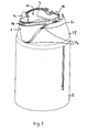
- FIGS. 1 to 10 show a kettle according to the invention 1. With the FIGS. 1 to 9 the installation of the kettle 1 is clarified and the FIG. 10 shows the fully assembled kettle 1 in a sectional view.
- the water heater 1 comprises a cylindrical and in the upper region conical shell 2 made of brushed aluminum and a water tank 3 made of plastic.
- the water tank 3 comprises a substantially cylindrical hollow body 3a made of plastic with an upper opening 3b, via which the fully assembled kettle 1 can be filled with water.
- the hollow body 3a further comprises a spout 3c molded onto the hollow body 3a for pouring out water, and a water level indicator 3d is arranged on the hollow body 3a. At its lower end, the hollow body 3a is closed with a provided for heating the water circular planar heater 3e.
- the heater 3e which thus forms the bottom of the water tank 3, is in the case of the present Embodiment supplied in operation by means of a well-known plug-in coupling and a socket 5 with electrical energy.
- the plug-in coupling comprises two mutually contactable part clutches 4a and 4b, of which the part-coupling 4a is fixed to the heater 3e and the part-coupling 4b in the base 5. In the case of the present embodiment, it is therefore a wireless kettle 1.
- the jacket 2 comprises an upper opening 2a and a circular lower opening 2b.
- the upper opening 2a is at least partially circular and comprises recesses 2c and 2d adapted to the spout 3b and a handle 6, and a recess 2e adapted to the water level indicator 3d.
- the jacket 2 runs in such a way conically in an upper section 2f that the cross section of the upper opening 2a is significantly smaller than the surface of the heater 3e.
- the upper opening 2a of the shell 2 is thus significantly smaller than the bottom of the water tank.
- the water tank 3 is pushed from below into the shell 2 or the shell 2 is slipped over the water tank 3, so that the spout 3c of the water tank 3 is located above the upper opening 2a of the shell 2.
- the water container 3 is fixed with a plastic nosepiece 7, which is adapted to the spout 3 c and the recess 2 c of the upper opening 2 a of the jacket 2, as described in US Pat Fig. 2 is shown.
- the Schnaupenblende 7 comprises on the Schnaupenblende 7 integrally formed locking tongues 7a, which engage behind the jacket 2 on the inside in the region of the recess 2c and which are designed such that in the assembled state of the kettle 1, the outer surfaces of the Schnaupenblende 7 and the shell 2 as possible without a gap and finish flush.
- the Schnaupenblende 7 further comprises an integrally formed on the Schnaupenblende 7 locking element 7b, which is engaged in the assembled state of the kettle 1 in a formed on the spout 3c of the water tank 4 counter-locking element.
- the handle 6 is mounted, which in the FIGS. 3 and 4 is shown.
- the hollow body 3 a of the water tank 3 in the upper area opposite the spout 3 c two integrally formed on the hollow body 3 a notches 8.
- the handle 6, which is made of plastic, the notches 8 of the hollow body 3 a corresponding and integrally formed on the handle 6 guide rails 6a.
- the guide rails 6a of the handle 6 from above in the direction of the arrow P (see. Fig. 4 ) is pushed into the notches 8 of the hollow body 8 until the handle 6 and the hollow body 3 a latch in a predetermined position miteinender.
- the handle 6 is thus firmly connected to the hollow body 3 a of the water tank 3.
- the handle 6 further comprises a recess 6b integrally formed on the handle 6, which engages in the region of the recess 2d of the jacket 2 in the assembled state of the kettle 1.
- the recess 6b of the handle 6 is further designed such that the handle 6 and the shell 2 complete as gap-free and flush.
- the hollow body 3 a pushes the handle 6 in the region of its recess 6 b in the assembled state of the kettle 1 against the jacket 2, whereby the water tank 3 is clamped by the handle 6 with the jacket 2.
- part-ring-shaped aperture 9 made of plastic between the upper opening 2a of the shell 2 and the upper opening 3b of the hollow body 3a of the water tank 3 is pressed.
- the panel 9 includes molded locking elements 9a, which engage below the spout 3c of the water tank 3 and molded locking elements 9b, which engage with the handle 6.
- the panel 9 further comprises a groove 9c, which engages with the upper opening 3b of the water tank 3 final edge 3f in the assembled state of the kettle 1. As a result, the aperture 9 is attached to the water tank 3.
- the panel 9 is further designed so that it presses in the assembled state of the kettle 1 from the inside against the edge of the upper opening 2a of the shell 2, whereby the shell 2 and the water tank 3 are clamped together in their upper regions and therefore the water tank. 3 is attached to the jacket 2 in the upper area.
- the shutter 9 is formed so as to cover the gap between the edge 3 f of the upper opening 3 a of the water tank 3 and the edge of the upper opening 2 a of the shell 2.
- the jacket 2 is then in its lower region via a made of plastic ring 10 and four made of sheet metal T-shaped leaf springs 11 clamped in the lower region of the water tank 3.
- Each of the four leaf springs 11 comprises a spring clip 11 a, a spring tongue 11 b and a stop surface 11 c.
- the ring 10 is first placed on the edge 2g of the lower opening 2b of the shell 2.
- the ring 10 has a peripheral edge 10a, with which the ring 10 is supported on the edge 2g.
- the ring 10 also comprises four recesses 10 b, is guided by the subsequently each one of the leaf spring 11.
- the individual leaf springs 11 are guided through the recesses 10b such that the spring clips 11a are supported on the ring 10.
- the individual leaf springs 11 are pushed so far along the inner surface of the shell 2 until the spring tongues 11 b via a, integrally formed on the hollow body 3 a, in the Figures 3 and 9 3f shown ring and snapping behind the ring 3f.
- the stop surfaces 11 c prevent the leaf springs 11 from being pushed too far into the inner surface of the shell 2.
- the leaf springs 11 are further dimensioned such that the spring clip 11 b are biased when the kettle 1 mounted. As a result, the ring 10 and the water tank 3 are pressed against each other. Since the ring 10 in turn rests on the edge 2g of the shell 2, the lower portion of the water tank 3 is pulled against the edge 2g of the lower opening 2b of the shell 2.
- the hollow body 3a of the water tank 3 due to the heated water, so the hollow body 3a can extend only along its longitudinal axis down, since the water tank 3 at the upper end of the jacket 2 fixed and at the bottom by the leaf springs 11 is slidably mounted.
- the water tank 3 is clamped by the leaf springs 11 in the lower area with the jacket 2, also results in a relatively good attachment of the shell 2 on the water tank 3, although the hollow body 3 a of the water tank 3 expands due to the heating down.
- the jacket 2 is pulled down so far that it covers the water tank 3, regardless of the expansion caused by the heating of the water.
- the circular aperture 12 is connected to three in the Fig. 8 Screws not shown screwed to the heating 3e connected part coupling 4a.
- the holes provided for the screws are provided with the reference numeral 12a.
- the circular aperture 12 comprises a circular opening 12b, through which the part coupling 4a connected to the heater 3e can be contacted.
Landscapes
- Engineering & Computer Science (AREA)
- Food Science & Technology (AREA)
- Cookers (AREA)
- Saccharide Compounds (AREA)
Description
- Die Erfindung betrifft einen Wasserkocher.
- Bekannt sind kleine Haushaltsgeräte, wie z.B. Standmixer und insbesondere Wasserkocher, die einen Lebensmittelbehälter, im Falle des Wasserkochers einen Wasserbehälter, umfassen, der von einem rohrförmigen Mantel beispielsweise aus Aluminium oder Edelstahl umgeben ist.
- Die bekannten kleinen Haushaltgeräte werden montiert, indem deren Lebensmittelbehälter von oben in die rohrförmigen Mäntel geschoben und anschließend an den Mänteln befestigt werden. Diese Art der Montage ist äußerst einfach und schnell und daher sehr kostengünstig. Damit jedoch das kleine Haushaltsgerät auf diese einfache und schnelle und daher kostengünstige Art zusammengebaut werden kann, muss die obere Öffnung des Mantels genügend groß sein, damit der Lebensmittelbehälter durch diese obere Öffnung passt. Die
GB 2 379 214 A - Die Aufgabe der Erfindung ist es daher, einen elektrischen Wasserkocher mit einer flexibleren Formgestaltung bereitzustellen, wobei der Wasserbehälter aus Kunststoff gefertigt ist.
- Die Aufgabe der Erfindung wird gelöst durch einen elektrischen Wasserkocher mit einem Wasserbehälter, der einen Boden und eine Öffnung, über die der Wasserbehälter mit Wasser befüllbar ist, umfasst, und mit einem den Wasserbehälter umhüllenden zylinderförmigen Mantel, der eine obere Öffnung umfasst, wobei der Mantel in seinem oberen Bereich konisch ausgebildet, die Querschnittsfläche der oberen Öffnung des Mantels kleiner als die Querschnittsfläche des Bodens des Wasserbehälter und der Mantel in seinem oberen konischen Bereich fest an dem oberen Bereich des Wasserbehälters gelagert ist, der dadurch gekennzeichnet ist, dass der Wasserbehälter (3) an seinem unteren Bereich (3f) gegenüber dem Mantel (2) bezüglich der Längsachse des Wasserbehälters (3) mit wenigstens einem Federelement (11) verschieblich gelagert ist. Durch die konische Ausgestaltung des Mantels kann der Wasserbehälter relativ gut an dem Mantel fest gelagert werden, indem er z.B. mit wenigstens einem weiteren Bauteil in diesem Bereich des Mantels befestigt ist. Die feste Lagerung ist insbesondere dann gut, wenn der Mantel mit dem Wasserbehälter mittels dem weiteren Bauteil verspreizt oder verkeilt ist.
- Umfasst der elektrische Wasserkocher eine an dem Wasserbehälter angeformte Schnaupe zum Ausgießen von Wasser und der Mantel in seinem konischen Bereich eine der Schnaupe entsprechenden Aussparung, so kann der Wasserbehälter insbesondere mit einer der Aussparung angepassten Schnaupenblende am Mantel fest gelagert werden.
- Vorteilhaft ist es auch, wenn der elektrische Wasserkocher einen Griff umfasst, der mit dem Wasserbehälter verrastet ist. Bei der Montage des Wasserkochers kann somit zunächst der Mantel über den Wasserbehälter gestülpt und anschließend der Griff mit dem Wasserbehälter verrastet werden. Der Mantel ist dann besonders gut am Wasserbehälter fest gelagert, wenn der Mantel in seinem konischen Bereich eine dem Griff entsprechende Aussparung aufweist und der Griff nach der Verrastung mit dem Wasserbehälter gegen den Rand der für den Griff vorgesehenen Aussparung des Mantels drückt.
- Eine weitere vorteilhafte Ausgestaltung des erfindungsgemäßen Wasserkochers ergibt sich, wenn das wenigstens eine Bauteil, mit dem der Wasserbehälter am konischen Bereich des Mantels fest gelagert ist, eine Blende ist, die einen Spalt, der von dem Rand der oberen Öffnung des Wasserbehälters und dem Rand der oberen Öffnung des Mantels begrenzt wird, abdeckt. Die Blende ist also nicht nur für eine gute Befestigung des Mantels an dem Wasserbehälter vorgesehen, sondern deckt auch besagten Spalt ab, was dem Erscheinungsbild des Wasserkochers zugute kommt.
- Wenn der Wasserbehälter aus Kunststoff gefertigt ist, kann das mit dem Wasserkocher erhitzte Wasser den Wasserbehälter ausdehnen, wodurch sich der Wasserbehälter gegenüber dem Mantel leicht verschieben kann. Daher ist vorgesehen, dass der Wasserbehälter an seinem unteren gegenüber dem Mantel bezüglich der Längsachse des Wasserbehälters mit wenigstens einem Federelement verschieblich gelagert ist. Das Federelement ist vorzugsweise vorgespannt, dass es den unteren Bereich des Wasserbehälters und den unteren Bereich des Mantels gegeneinander zieht. Durch die verschiebliche Lagerung kann sich der Wasserbehälter innerhalb des Mantels ausdehnen, ohne dass dies von außen sichtbar ist.
- Ein Ausführungsbeispiel eines erfindungsgemäßen Wasserkochers und dessen Montage wird exemplarisch anhand der folgenden schematischen Figuren erläutert. Es zeigen:
- Figuren 1 bis 9
- einen Wasserkocher in unterschiedlichen Stadien seiner Montage und
- Figur 10
- eine Seitenansicht des Wasserkoches in geschnittener Darstellung.
- Die
Figuren 1 bis 10 zeigen einen erfindungsgemäßen Wasserkocher 1. Mit denFiguren 1 bis 9 wird die Montage des Wasserkochers 1 verdeutlicht und dieFigur 10 zeigt den fertig montierten Wasserkocher 1 in geschnittener Darstellung. - Im Falle des vorliegenden Ausführungsbeispiels umfasst der Wasserkocher 1 einen zylinderförmigen und im oberen Bereich konisch ausgebildeten Mantel 2 aus gebürstetem Aluminium und einen Wasserbehälter 3 aus Kunststoff. Der Wasserbehälter 3 umfasst einen im Wesentlichen zylinderförmigen Hohlkörper 3a aus Kunststoff mit einer oberen Öffnung 3b, über die der fertig montierte Wasserkocher 1 mit Wasser befüllt werden kann. Der Hohlkörper 3a umfasst ferner eine an den Hohlkörper 3a angeformte Schnaupe 3c zum Ausgießen von Wasser und es ist an dem Hohlkörper 3a eine Wasserstandsanzeige 3d angeordnet. An seinem unteren Ende ist der Hohlkörper 3a mit einer zur Erwärmung des Wassers vorgesehenen kreisförmigen flächenhaften Heizung 3e abgeschlossen. Die Heizung 3e, die somit den Boden des Wasserbehälters 3 bildet, wird im Falle des vorliegenden Ausführungsbeispiels im Betrieb mittels einer allgemein bekannten Steckkupplung und einem Sockel 5 mit elektrischer Energie versorgt. Die Steckkupplung umfasst zwei gegenseitig kontaktierbare Teilkupplungen 4a und 4b, von denen die Teilkupplung 4a an der Heizung 3e und die Teilkupplung 4b in dem Sockel 5 befestigt ist. Im Falle des vorliegenden Ausführungsbeispiels handelt es sich also um einen kabellosen Wasserkocher 1.
- Der Mantel 2 umfasst eine obere Öffnungen 2a und eine kreisförmige untere Öffnung 2b. Die obere Öffnung 2a ist zumindest teilweise kreisförmig und umfasst an die Schnaupe 3b und einen Griff 6 angepasste Aussparungen 2c und 2d, sowie eine an die Wasserstandsanzeige 3d angepasste Aussparung 2e. Des Weiteren läuft der Mantel 2 in einem oberen Abschnitt 2f derart stark konisch zu, dass der Querschnitt der oberen Öffnung 2a deutlich kleiner als die Fläche der Heizung 3e ist. Die obere Öffnung 2a des Mantels 2 ist also deutlich kleiner als der Boden des Wasserbehälters 3.
- Für die Montage des Wasserkochers 1 wird zunächst der Wasserbehälter 3 von unten in den Mantel 2 geschoben oder der Mantel 2 über den Wasserbehälter 3 gestülpt, so dass die Schnaupe 3c des Wasserbehälters 3 sich oberhalb der oberen Öffnung 2a des Mantels 2 befindet.
- Anschließend wird im Bereich der Schnaupe 3c der Wasserbehälter 3 mit einem an die Schnaupe 3c und der Aussparung 2c der oberen Öffnung 2a des Mantels 2 angepassten Schnaupenblende 7 aus Kunststoff fixiert, wie dies in der
Fig. 2 dargestellt ist. Die Schnaupenblende 7 umfasst an die Schnaupenblende 7 angeformte Rastzungen 7a, die den Mantel 2 an dessen Innenseite im Bereich der Aussparung 2c hintergreifen und die derart ausgeführt sind, dass im montiertem Zustand des Wasserkochers 1 die Außenflächen der Schnaupenblende 7 und des Mantels 2 möglichst spaltfrei und bündig abschließen. Die Schnaupenblende 7 umfasst ferner ein an die Schnaupenblende 7 angeformtes Rastelement 7b, das im montiertem Zustand des Wasserkochers 1 in ein an der Schnaupe 3c des Wasserbehälters 4 angeformtes Gegenrastelement eingerastet ist. - Anschließend wird der Griff 6 montiert, was in den
Figuren 3 und 4 gezeigt ist. Wie es in derFig. 3 zu sehen ist, umfasst der Hohlkörper 3a des Wasserbehälters 3 im oberen Bereich gegenüber der Schnaupe 3c zwei an den Hohlkörper 3a angeformte Kerben 8. Der Griff 6, der aus Kunststoff gefertigt ist, umfasst den Kerben 8 des Hohlkörpers 3a entsprechende und an den Griff 6 angeformte Führungsschienen 6a. Für die Montage des Griffs 6 werden die Führungsschienen 6a des Griffs 6 von oben in Richtung des Pfeils P (vgl.Fig. 4 ) in die Kerben 8 des Hohlkörpers 8 geschoben, bis der Griff 6 und der Hohlkörper 3a in einer vorgegebenen Stellung miteinender verrasten. Der Griff 6 ist somit mit dem Hohlkörper 3a des Wasserbehälters 3 fest verbunden. - Der Griff 6 umfasst ferner eine an den Griff 6 angeformte Aussparung 6b, die im Bereich der Aussparung 2d des Mantels 2 diesen im zusammengebautem Zustand des Wasserkochers 1 hintergreift. Die Aussparung 6b des Griffs 6 ist ferner derart ausgebildet, dass der Griff 6 und der Mantel 2 möglichst spaltfrei und bündig abschließen. Außerdem drückt der Hohlkörper 3a den Griff 6 im Bereich seiner Aussparung 6b im montiertem Zustand des Wasserkochers 1 gegen den Mantel 2, wodurch der Wasserbehälter 3 über den Griff 6 mit dem Mantel 2 verspannt ist.
- Um den Mantel 2 verbessert an dessen oberem Bereich mit dem Wasserbehälter 3 fest zu lagern, wird im Falle des vorliegenden Ausführungsbeispiels anschließend ein in der
Fig. 5 näher dargestellte teilringförmige Blende 9 aus Kunststoff zwischen der oberen Öffnung 2a des Mantels 2 und der oberen Öffnung 3b des Hohlkörpers 3a des Wasserbehälters 3 gedrückt. Die Blende 9 umfasst angeformte Rastelemente 9a, die unterhalb der Schnaupe 3c des Wasserbehälters 3 eingreifen und angeformte Rastelemente 9b, die mit dem Griff 6 verrasten. Die Blende 9 umfasst ferner eine Nut 9c, die mit der die obere Öffnung 3b des Wasserbehälters 3 abschließenden Kante 3f im montiertem Zustand des Wasserkochers 1 verrastet. Dadurch ist die Blende 9 an dem Wasserbehälter 3 befestigt. - Die Blende 9 ist ferner derart ausgeführt, dass sie im zusammengebautem Zustand des Wasserkochers 1 von innen gegen den Rand der oberen Öffnung 2a des Mantels 2 drückt, wodurch der Mantel 2 und der Wasserbehälter 3 in ihren oberen Bereichen miteinander verspannt sind und daher der Wasserbehälter 3 am Mantel 2 im oberen Bereich befestigt ist. Außerdem ist die Blende 9 derart ausgebildet, dass sie den Spalt zwischen der Kante 3f der oberen Öffnung 3a des Wasserbehälters 3 und dem Rand der oberen Öffnung 2a des Mantels 2 abdeckt.
- Im Falle des vorliegenden Ausführungsbeispiels wird anschließend der Mantel 2 in seinem unteren Bereich über einen aus Kunststoff gefertigten Ring 10 und vier aus Blech gefertigte T-förmige Blattfedern 11 im unteren Bereich des Wasserbehälters 3 verspannt. Jede der vier Blattfedern 11 umfasst einen Federbügel 11a, eine Federzunge 11b und eine Anschlagfläche 11 c.
- Für diesen Teil der Montage des Wasserkochers 1, der in den
Figuren 6 und 7 verdeutlicht ist, wird zunächst der Ring 10 auf den Rand 2g der unteren Öffnung 2b des Mantels 2 gelegt. Der Ring 10 hat eine umlaufende Kante 10a, mit der sich der Ring 10 auf dem Rand 2g abstützt. Der Ring 10 umfasst außerdem vier Aussparungen 10b, durch die anschließend jeweils eine der Blattfeder 11 geführt wird. Die einzelnen Blattfedern 11 werden derart durch die Aussparungen 10b geführt, dass sich die Federbügel 11a am Ring 10 abstützen. Die einzelnen Blattfedern 11 werden so weit entlang der Innenfläche des Mantels 2 geschoben, bis die Federzungen 11 b über einen, an dem Hohlkörper 3a angeformten, in denFiguren 3 und9 dargestellten Ring 3f geschoben werden und hinter dem Ring 3f verschnappen. Die Anschlagflächen 11c verhindern, dass die Blattfedern 11 zu weit in den entlang der Innenfläche des Mantels 2 geschoben werden. Die Blattfedern 11 sind ferner derart dimensioniert, dass die Federbügel 11 b beim montiertem Wasserkocher 1 vorgespannt sind. Dadurch wird der Ring 10 und der Wasserbehälter 3 aneinander gedrückt. Da der Ring 10 wiederum auf dem Rand 2g des Mantels 2 aufliegt, wird der untere Bereich des Wasserbehälters 3 gegen den Rand 2g der unteren Öffnung 2b des Mantels 2 gezogen. - Dehnt sich nun im Betrieb des Wasserkochers 1 der Hohlkörper 3a des Wasserbehälters 3 aufgrund des erwärmten Wassers aus, so kann sich der Hohlkörper 3a nur längs seiner Längsachse nach unten ausdehnen, da der Wasserbehälter 3 am oberen Ende am Mantel 2 fest und am unteren Ende mittels der Blattfedern 11 verschieblich gelagert ist. Da zudem der Wasserbehälter 3 mittels der Blattfedern 11 im untern Bereich mit dem Mantel 2 verspannt ist, ergibt sich außerdem eine relativ gute Befestigung des Mantels 2 am Wasserbehälter 3, obwohl sich der Hohlkörper 3a des Wasserbehälters 3 aufgrund der Erwärmung nach unten ausdehnt. Ferner ist im Falle des vorliegenden Ausführungsbeispiels der Mantel 2 derart weit nach unten gezogen, dass er unabhängig von der durch die Erwärmung des Wassers bedingten Ausdehnung den Wasserbehälter 3 überdeckt.
- Um die untere Öffnung 2b des Mantels 2 zu verschließen, wird, wie in der
Fig. 8 dargestellt, anschließend die Öffnung mit einer kreisförmigen Blende 12 aus Kunststoff abgedeckt. Die kreisförmige Blende 12 wird mit drei in derFig. 8 nicht dargestellten Schrauben mit der Heizung 3e verbundenen Teilkupplung 4a verschraubt. Die für die Schrauben vorgesehenen Löcher sind mit dem Bezugszeichen 12a versehen. Wie es derFig. 8 zu entnehmen ist, umfasst die kreisförmige Blende 12 eine runde Öffnung 12b, durch die die mit der Heizung 3e verbundene Teilkupplung 4a kontaktierbar ist. - Im Betrieb des fertig montierten Wasserkochers 1 sitzt der Wasserbehälter 3 mit montiertem Mantel 2 mit der kreisförmigen Blende 12 auf dem Sockel 5 und die Teilkupplung 4a kontaktiert die Teilkupplung 4b elektrisch, so dass die Heizung 3e des Wasserkochers 1 im Betrieb über die Steckkupplung mit elektrischer Energie versorgt wird. In der
Fig. 9 ist der Wasserbehälter 3 mit montiertem Mantel 2 leicht abgesetzt zum Sockel 5 dargestellt. Die kreisförmige Blende 12 ist über die Teilkupplung 4a direkt mit dem Wasserbehälter 3 des Wasserkochers 1 verbunden. Folglich sitzt im Betrieb des Wasserkochers 1 nicht der Mantel 2, sondern der Wasserbehälter 3 über die Teilkupplung 4a und der kreisförmigen Blende 12 auf dem Sockel 5.
Claims (9)
- Elektrischer Wasserkocher mit einem Wasserbehälter (3), der einen Boden (3e) und eine Öffnung (3b), über die der Wasserbehälter (3) mit Wasser befüllbar ist, umfasst, und mit einem den Wasserbehälter (3) umhüllenden zylinderförmigen Mantel (2), der eine obere Öffnung (2a) umfasst, wobei der Mantel (2) in seinem oberen Bereich (2f) konisch ausgebildet, die Querschnittsfläche der oberen Öffnung (2a) des Mantels (2) kleiner als die Querschnittsfläche des Bodens (3e) des Wasserbehälters (3) und der Mantel (2) in seinem oberen konischen Bereich (2f) fest an dem oberen Bereich des Wasserbehälters (3) gelagert ist, dadurch gekennzeichnet, dass der Wasserbehälter (3) an seinem unteren Bereich (3f) gegenüber dem Mantel (2) bezüglich der Längsachse des Wasserbehälters (3) mit wenigstens einem Federelement (11) verschieblich gelagert ist.
- Elektrischer Wasserkocher nach Anspruch 1, dadurch gekennzeichnet, dass der Wasserbehälter (3) mit wenigstens einem weiteren Bauteil (6, 7, 9) an dem konischen Bereich (2f) des Mantels (2) gelagert ist.
- Elektrischer Wasserkocher nach Anspruch 2, dadurch gekennzeichnet, dass an dem Wasserbehälter (3) eine Schnaupe (3c) zum Ausgießen von Wasser angeformt ist und der Mantel (2) in seinem konischen Bereich (2f) eine der Schnaupe (2c) entsprechenden Aussparung (2c) aufweist.
- Elektrischer Wasserkocher nach Anspruch 3, dadurch gekennzeichnet, dass das wenigstens eine Bauteil, mit dem der Wasserbehälter (3) in seinem oberen Bereich am oberen Bereich (2f) des Mantels (2) fest gelagert ist, eine Schnaupenblende (7) ist.
- Elektrischer Wasserkocher nach einem der Ansprüche 1 bis 4, dadurch gekennzeichnet, dass der Wasserkocher (1) einen Griff (6) umfasst, der mit dem Wasserbehälter (3) verrastet ist.
- Elektrischer Wasserkocher nach Anspruch 5, dadurch gekennzeichnet, dass der Mantel (2) in seinem konischen Bereich (2f) eine dem Griff (6) entsprechende Aussparung (2d) aufweist.
- Elektrischer Wasserkocher nach Anspruch 6, dadurch gekennzeichnet, dass der Griff (6) gegen den Rand der für den Griff (6) vorgesehenen Aussparung (2d) des Mantels (2) drückt.
- Elektrischer Wasserkocher nach einem der Ansprüche 2 bis 7, dadurch gekennzeichnet, dass das wenigstens eine Bauteil, mit dem der Wasserbehälter (3) am konischen Bereich (2f) des Mantels (2) fest gelagert ist, eine Blende (9) ist, die einen Spalt, der von dem Rand (3f) der oberen Öffnung (3b) des Wasserbehälters (3) und dem Rand der oberen Öffnung (2a) des Mantels (2) begrenzt wird, abdeckt.
- Elektrischer Wasserkocher nach einem der Ansprüche 1 bis 8, dadurch gekennzeichnet, dass das wenigstens eine Federelement (11) derart vorgespannt ist, dass es den unteren Bereich (3f) des Wasserbehälters (3) und den unteren Bereich (2g) des Mantels (2) gegeneinander zieht.
Applications Claiming Priority (2)
| Application Number | Priority Date | Filing Date | Title |
|---|---|---|---|
| DE102005006352A DE102005006352A1 (de) | 2005-02-11 | 2005-02-11 | Elektrischer Wasserkocher und Verfahren zur Montage eines kleinen Haushaltsgerätes |
| PCT/EP2006/050553 WO2006084804A1 (de) | 2005-02-11 | 2006-01-31 | Elektrischer wasserkocher und verfahren zur montage eines kleinen haushaltsgerätes |
Publications (2)
| Publication Number | Publication Date |
|---|---|
| EP1850712A1 EP1850712A1 (de) | 2007-11-07 |
| EP1850712B1 true EP1850712B1 (de) | 2011-01-05 |
Family
ID=36287679
Family Applications (1)
| Application Number | Title | Priority Date | Filing Date |
|---|---|---|---|
| EP06707922A Expired - Lifetime EP1850712B1 (de) | 2005-02-11 | 2006-01-31 | Elektrischer wasserkocher |
Country Status (5)
| Country | Link |
|---|---|
| EP (1) | EP1850712B1 (de) |
| CN (1) | CN101119666B (de) |
| AT (1) | ATE493917T1 (de) |
| DE (2) | DE102005006352A1 (de) |
| WO (1) | WO2006084804A1 (de) |
Families Citing this family (2)
| Publication number | Priority date | Publication date | Assignee | Title |
|---|---|---|---|---|
| FR2911769B1 (fr) * | 2007-01-26 | 2012-12-28 | Hameur Sa | Bouilloire electrique perfectionnee |
| EP3178652B1 (de) | 2015-12-07 | 2018-06-06 | Akzenta Paneele + Profile GmbH | Dekorpaneel und verfahren zum herstellen eines solchen |
Family Cites Families (9)
| Publication number | Priority date | Publication date | Assignee | Title |
|---|---|---|---|---|
| GB1443847A (en) * | 1974-04-17 | 1976-07-28 | Kin Hip Metal Plastic Factory | Double-walled container apparatus for winding textile yarn |
| FR2662926A1 (fr) * | 1990-06-06 | 1991-12-13 | Moulinex Sa | Bouilloire electrique. |
| DE4333417A1 (de) * | 1993-09-30 | 1995-04-06 | Wmf Wuerttemberg Metallwaren | Kochgefäß mit Eigenheizung |
| DE19623617B4 (de) * | 1996-06-13 | 2004-05-27 | BSH Bosch und Siemens Hausgeräte GmbH | Wasserkocher mit Griff |
| DE19703949C1 (de) * | 1997-02-03 | 1998-06-10 | Bosch Siemens Hausgeraete | Optischer Füllstandsanzeiger |
| DE29903592U1 (de) * | 1999-02-27 | 1999-05-20 | Fritz Eichenauer Gmbh & Co Kg, 76870 Kandel | Flüssigkeitsgefäß |
| GB0004563D0 (en) * | 2000-02-25 | 2000-04-19 | Otter Controls Ltd | Improvements relating to electrically heated vessels |
| DE10123528A1 (de) * | 2001-05-15 | 2002-11-28 | Bsh Bosch Siemens Hausgeraete | Elektrischer Wasserkocher |
| GB2397214A (en) * | 2003-01-14 | 2004-07-21 | David Hirst | Thermally insulated kettle |
-
2005
- 2005-02-11 DE DE102005006352A patent/DE102005006352A1/de not_active Withdrawn
-
2006
- 2006-01-31 CN CN2006800046988A patent/CN101119666B/zh not_active Expired - Fee Related
- 2006-01-31 AT AT06707922T patent/ATE493917T1/de not_active IP Right Cessation
- 2006-01-31 WO PCT/EP2006/050553 patent/WO2006084804A1/de not_active Ceased
- 2006-01-31 DE DE502006008661T patent/DE502006008661D1/de not_active Expired - Lifetime
- 2006-01-31 EP EP06707922A patent/EP1850712B1/de not_active Expired - Lifetime
Also Published As
| Publication number | Publication date |
|---|---|
| DE502006008661D1 (de) | 2011-02-17 |
| ATE493917T1 (de) | 2011-01-15 |
| EP1850712A1 (de) | 2007-11-07 |
| DE102005006352A1 (de) | 2006-08-24 |
| CN101119666B (zh) | 2010-06-16 |
| CN101119666A (zh) | 2008-02-06 |
| WO2006084804A1 (de) | 2006-08-17 |
Similar Documents
| Publication | Publication Date | Title |
|---|---|---|
| DE69822525T2 (de) | Verbesserungen an elektrisch geheizten Kochgefässen | |
| DE2007145A1 (de) | Kocheinheit | |
| CH649419A5 (de) | Buerstenhalter fuer kleine kommutator-motoren, insbesondere fuer heimwerker-kombinationsmaschinen. | |
| DE102016208233B4 (de) | Induktionsheizeinrichtung und Induktionskochfeld mit einer solchen Induktionsheizeinrichtung | |
| EP1850712B1 (de) | Elektrischer wasserkocher | |
| DE202013104227U1 (de) | Elektrischer Samowar | |
| EP2045405B1 (de) | Betätigungsplatte für eine Betätigungsvorrichtung einer Spüleinrichtung | |
| EP1850711B1 (de) | Elektrischer wasserkocher | |
| DE102009048487A1 (de) | Ventilkartusche | |
| DE102009012946A1 (de) | Ventileinrichtung | |
| AT5058U1 (de) | Griffanordnung insbesondere für möbel | |
| DE10336776B4 (de) | Einfüllstutzen für den Kraftstoffbehälter eines Kraftfahrzeuges mit einem automatischen Tankverschluss | |
| EP1541069B1 (de) | Wasserkessel | |
| DE102009050550B4 (de) | Thermostatventil | |
| DE1565512C3 (de) | ||
| WO2004023947A1 (de) | Elektrischer wasserkocher | |
| DE202014100217U1 (de) | Gargerät | |
| EP1705282B1 (de) | Dampfbügeltisch | |
| EP2138770A2 (de) | Haushaltsgerät, insbesondere Dunstabzugshaube, mit einem Scharnier und Scharnier für ein Haushaltsgerät | |
| DE20308941U1 (de) | Heizeinrichtung, insbesondere thermostatisches Arbeitselement mit einer solchen Heizeinrichtung | |
| DE102021106932A1 (de) | Kochgeschirr für ein Induktionskochfeld | |
| DE102006009941B4 (de) | In ein Kraftfahrzeug einbaubarer Aschenbecher | |
| EP1110046B1 (de) | Kältegerät | |
| EP1627398B1 (de) | Schaltervorrichtung | |
| DE102009032385B3 (de) | Beheizbarer Wasserkessel mit einem eine Deckelöffnung aufweisenden Deckel |
Legal Events
| Date | Code | Title | Description |
|---|---|---|---|
| PUAI | Public reference made under article 153(3) epc to a published international application that has entered the european phase |
Free format text: ORIGINAL CODE: 0009012 |
|
| 17P | Request for examination filed |
Effective date: 20070911 |
|
| AK | Designated contracting states |
Kind code of ref document: A1 Designated state(s): AT BE BG CH CY CZ DE DK EE ES FI FR GB GR HU IE IS IT LI LT LU LV MC NL PL PT RO SE SI SK TR |
|
| DAX | Request for extension of the european patent (deleted) | ||
| 17Q | First examination report despatched |
Effective date: 20090416 |
|
| GRAP | Despatch of communication of intention to grant a patent |
Free format text: ORIGINAL CODE: EPIDOSNIGR1 |
|
| RTI1 | Title (correction) |
Free format text: ELECTRIC KETTLE |
|
| GRAS | Grant fee paid |
Free format text: ORIGINAL CODE: EPIDOSNIGR3 |
|
| GRAA | (expected) grant |
Free format text: ORIGINAL CODE: 0009210 |
|
| AK | Designated contracting states |
Kind code of ref document: B1 Designated state(s): AT BE BG CH CY CZ DE DK EE ES FI FR GB GR HU IE IS IT LI LT LU LV MC NL PL PT RO SE SI SK TR |
|
| REG | Reference to a national code |
Ref country code: GB Ref legal event code: FG4D Free format text: NOT ENGLISH |
|
| REG | Reference to a national code |
Ref country code: CH Ref legal event code: EP |
|
| REG | Reference to a national code |
Ref country code: IE Ref legal event code: FG4D Free format text: LANGUAGE OF EP DOCUMENT: GERMAN |
|
| REF | Corresponds to: |
Ref document number: 502006008661 Country of ref document: DE Date of ref document: 20110217 Kind code of ref document: P |
|
| REG | Reference to a national code |
Ref country code: DE Ref legal event code: R096 Ref document number: 502006008661 Country of ref document: DE Effective date: 20110217 |
|
| REG | Reference to a national code |
Ref country code: NL Ref legal event code: VDEP Effective date: 20110105 |
|
| PG25 | Lapsed in a contracting state [announced via postgrant information from national office to epo] |
Ref country code: SI Free format text: LAPSE BECAUSE OF FAILURE TO SUBMIT A TRANSLATION OF THE DESCRIPTION OR TO PAY THE FEE WITHIN THE PRESCRIBED TIME-LIMIT Effective date: 20110105 |
|
| LTIE | Lt: invalidation of european patent or patent extension |
Effective date: 20110105 |
|
| PG25 | Lapsed in a contracting state [announced via postgrant information from national office to epo] |
Ref country code: LV Free format text: LAPSE BECAUSE OF FAILURE TO SUBMIT A TRANSLATION OF THE DESCRIPTION OR TO PAY THE FEE WITHIN THE PRESCRIBED TIME-LIMIT Effective date: 20110105 Ref country code: LT Free format text: LAPSE BECAUSE OF FAILURE TO SUBMIT A TRANSLATION OF THE DESCRIPTION OR TO PAY THE FEE WITHIN THE PRESCRIBED TIME-LIMIT Effective date: 20110105 Ref country code: PT Free format text: LAPSE BECAUSE OF FAILURE TO SUBMIT A TRANSLATION OF THE DESCRIPTION OR TO PAY THE FEE WITHIN THE PRESCRIBED TIME-LIMIT Effective date: 20110505 Ref country code: SE Free format text: LAPSE BECAUSE OF FAILURE TO SUBMIT A TRANSLATION OF THE DESCRIPTION OR TO PAY THE FEE WITHIN THE PRESCRIBED TIME-LIMIT Effective date: 20110105 Ref country code: GR Free format text: LAPSE BECAUSE OF FAILURE TO SUBMIT A TRANSLATION OF THE DESCRIPTION OR TO PAY THE FEE WITHIN THE PRESCRIBED TIME-LIMIT Effective date: 20110406 Ref country code: IS Free format text: LAPSE BECAUSE OF FAILURE TO SUBMIT A TRANSLATION OF THE DESCRIPTION OR TO PAY THE FEE WITHIN THE PRESCRIBED TIME-LIMIT Effective date: 20110505 Ref country code: ES Free format text: LAPSE BECAUSE OF FAILURE TO SUBMIT A TRANSLATION OF THE DESCRIPTION OR TO PAY THE FEE WITHIN THE PRESCRIBED TIME-LIMIT Effective date: 20110416 |
|
| BERE | Be: lapsed |
Owner name: BSH BOSCH UND SIEMENS HAUSGERATE G.M.B.H. Effective date: 20110131 |
|
| REG | Reference to a national code |
Ref country code: IE Ref legal event code: FD4D |
|
| PG25 | Lapsed in a contracting state [announced via postgrant information from national office to epo] |
Ref country code: NL Free format text: LAPSE BECAUSE OF FAILURE TO SUBMIT A TRANSLATION OF THE DESCRIPTION OR TO PAY THE FEE WITHIN THE PRESCRIBED TIME-LIMIT Effective date: 20110105 Ref country code: FI Free format text: LAPSE BECAUSE OF FAILURE TO SUBMIT A TRANSLATION OF THE DESCRIPTION OR TO PAY THE FEE WITHIN THE PRESCRIBED TIME-LIMIT Effective date: 20110105 Ref country code: MC Free format text: LAPSE BECAUSE OF NON-PAYMENT OF DUE FEES Effective date: 20110131 Ref country code: BG Free format text: LAPSE BECAUSE OF FAILURE TO SUBMIT A TRANSLATION OF THE DESCRIPTION OR TO PAY THE FEE WITHIN THE PRESCRIBED TIME-LIMIT Effective date: 20110405 Ref country code: CY Free format text: LAPSE BECAUSE OF FAILURE TO SUBMIT A TRANSLATION OF THE DESCRIPTION OR TO PAY THE FEE WITHIN THE PRESCRIBED TIME-LIMIT Effective date: 20110105 Ref country code: PL Free format text: LAPSE BECAUSE OF FAILURE TO SUBMIT A TRANSLATION OF THE DESCRIPTION OR TO PAY THE FEE WITHIN THE PRESCRIBED TIME-LIMIT Effective date: 20110105 |
|
| REG | Reference to a national code |
Ref country code: CH Ref legal event code: PL |
|
| PG25 | Lapsed in a contracting state [announced via postgrant information from national office to epo] |
Ref country code: CH Free format text: LAPSE BECAUSE OF NON-PAYMENT OF DUE FEES Effective date: 20110131 Ref country code: EE Free format text: LAPSE BECAUSE OF FAILURE TO SUBMIT A TRANSLATION OF THE DESCRIPTION OR TO PAY THE FEE WITHIN THE PRESCRIBED TIME-LIMIT Effective date: 20110105 Ref country code: LI Free format text: LAPSE BECAUSE OF NON-PAYMENT OF DUE FEES Effective date: 20110131 Ref country code: DK Free format text: LAPSE BECAUSE OF FAILURE TO SUBMIT A TRANSLATION OF THE DESCRIPTION OR TO PAY THE FEE WITHIN THE PRESCRIBED TIME-LIMIT Effective date: 20110105 Ref country code: IE Free format text: LAPSE BECAUSE OF FAILURE TO SUBMIT A TRANSLATION OF THE DESCRIPTION OR TO PAY THE FEE WITHIN THE PRESCRIBED TIME-LIMIT Effective date: 20110105 |
|
| PLBE | No opposition filed within time limit |
Free format text: ORIGINAL CODE: 0009261 |
|
| STAA | Information on the status of an ep patent application or granted ep patent |
Free format text: STATUS: NO OPPOSITION FILED WITHIN TIME LIMIT |
|
| PG25 | Lapsed in a contracting state [announced via postgrant information from national office to epo] |
Ref country code: SK Free format text: LAPSE BECAUSE OF FAILURE TO SUBMIT A TRANSLATION OF THE DESCRIPTION OR TO PAY THE FEE WITHIN THE PRESCRIBED TIME-LIMIT Effective date: 20110105 Ref country code: CZ Free format text: LAPSE BECAUSE OF FAILURE TO SUBMIT A TRANSLATION OF THE DESCRIPTION OR TO PAY THE FEE WITHIN THE PRESCRIBED TIME-LIMIT Effective date: 20110105 Ref country code: RO Free format text: LAPSE BECAUSE OF FAILURE TO SUBMIT A TRANSLATION OF THE DESCRIPTION OR TO PAY THE FEE WITHIN THE PRESCRIBED TIME-LIMIT Effective date: 20110105 Ref country code: BE Free format text: LAPSE BECAUSE OF NON-PAYMENT OF DUE FEES Effective date: 20110131 |
|
| 26N | No opposition filed |
Effective date: 20111006 |
|
| PG25 | Lapsed in a contracting state [announced via postgrant information from national office to epo] |
Ref country code: IT Free format text: LAPSE BECAUSE OF FAILURE TO SUBMIT A TRANSLATION OF THE DESCRIPTION OR TO PAY THE FEE WITHIN THE PRESCRIBED TIME-LIMIT Effective date: 20110105 |
|
| REG | Reference to a national code |
Ref country code: DE Ref legal event code: R097 Ref document number: 502006008661 Country of ref document: DE Effective date: 20111006 |
|
| REG | Reference to a national code |
Ref country code: AT Ref legal event code: MM01 Ref document number: 493917 Country of ref document: AT Kind code of ref document: T Effective date: 20110131 |
|
| PG25 | Lapsed in a contracting state [announced via postgrant information from national office to epo] |
Ref country code: AT Free format text: LAPSE BECAUSE OF NON-PAYMENT OF DUE FEES Effective date: 20110131 |
|
| PG25 | Lapsed in a contracting state [announced via postgrant information from national office to epo] |
Ref country code: LU Free format text: LAPSE BECAUSE OF NON-PAYMENT OF DUE FEES Effective date: 20110131 |
|
| PG25 | Lapsed in a contracting state [announced via postgrant information from national office to epo] |
Ref country code: TR Free format text: LAPSE BECAUSE OF FAILURE TO SUBMIT A TRANSLATION OF THE DESCRIPTION OR TO PAY THE FEE WITHIN THE PRESCRIBED TIME-LIMIT Effective date: 20110105 |
|
| PG25 | Lapsed in a contracting state [announced via postgrant information from national office to epo] |
Ref country code: HU Free format text: LAPSE BECAUSE OF FAILURE TO SUBMIT A TRANSLATION OF THE DESCRIPTION OR TO PAY THE FEE WITHIN THE PRESCRIBED TIME-LIMIT Effective date: 20110105 |
|
| REG | Reference to a national code |
Ref country code: FR Ref legal event code: PLFP Year of fee payment: 10 |
|
| REG | Reference to a national code |
Ref country code: DE Ref legal event code: R081 Ref document number: 502006008661 Country of ref document: DE Owner name: BSH HAUSGERAETE GMBH, DE Free format text: FORMER OWNER: BSH BOSCH UND SIEMENS HAUSGERAETE GMBH, 81739 MUENCHEN, DE Effective date: 20150407 |
|
| REG | Reference to a national code |
Ref country code: FR Ref legal event code: CD Owner name: BSH HAUSGERATE GMBH Effective date: 20151022 |
|
| REG | Reference to a national code |
Ref country code: FR Ref legal event code: PLFP Year of fee payment: 11 |
|
| REG | Reference to a national code |
Ref country code: FR Ref legal event code: PLFP Year of fee payment: 12 |
|
| REG | Reference to a national code |
Ref country code: FR Ref legal event code: PLFP Year of fee payment: 13 |
|
| PGFP | Annual fee paid to national office [announced via postgrant information from national office to epo] |
Ref country code: GB Payment date: 20200127 Year of fee payment: 15 Ref country code: DE Payment date: 20200131 Year of fee payment: 15 |
|
| PGFP | Annual fee paid to national office [announced via postgrant information from national office to epo] |
Ref country code: FR Payment date: 20200123 Year of fee payment: 15 |
|
| REG | Reference to a national code |
Ref country code: DE Ref legal event code: R119 Ref document number: 502006008661 Country of ref document: DE |
|
| GBPC | Gb: european patent ceased through non-payment of renewal fee |
Effective date: 20210131 |
|
| PG25 | Lapsed in a contracting state [announced via postgrant information from national office to epo] |
Ref country code: FR Free format text: LAPSE BECAUSE OF NON-PAYMENT OF DUE FEES Effective date: 20210131 |
|
| PG25 | Lapsed in a contracting state [announced via postgrant information from national office to epo] |
Ref country code: GB Free format text: LAPSE BECAUSE OF NON-PAYMENT OF DUE FEES Effective date: 20210131 Ref country code: DE Free format text: LAPSE BECAUSE OF NON-PAYMENT OF DUE FEES Effective date: 20210803 |