EP1850928B1 - Pion a sous-pieces declenchables - Google Patents
Pion a sous-pieces declenchables Download PDFInfo
- Publication number
- EP1850928B1 EP1850928B1 EP06710771.4A EP06710771A EP1850928B1 EP 1850928 B1 EP1850928 B1 EP 1850928B1 EP 06710771 A EP06710771 A EP 06710771A EP 1850928 B1 EP1850928 B1 EP 1850928B1
- Authority
- EP
- European Patent Office
- Prior art keywords
- pawn
- board
- trigger signal
- parts
- sub
- Prior art date
- Legal status (The legal status is an assumption and is not a legal conclusion. Google has not performed a legal analysis and makes no representation as to the accuracy of the status listed.)
- Expired - Lifetime
Links
Images



Classifications
-
- A—HUMAN NECESSITIES
- A63—SPORTS; GAMES; AMUSEMENTS
- A63F—CARD, BOARD, OR ROULETTE GAMES; INDOOR GAMES USING SMALL MOVING PLAYING BODIES; VIDEO GAMES; GAMES NOT OTHERWISE PROVIDED FOR
- A63F3/00—Board games; Raffle games
- A63F3/02—Chess; Similar board games
-
- A—HUMAN NECESSITIES
- A63—SPORTS; GAMES; AMUSEMENTS
- A63F—CARD, BOARD, OR ROULETTE GAMES; INDOOR GAMES USING SMALL MOVING PLAYING BODIES; VIDEO GAMES; GAMES NOT OTHERWISE PROVIDED FOR
- A63F2250/00—Miscellaneous game characteristics
- A63F2250/26—Miscellaneous game characteristics the game being influenced by physiological parameters
- A63F2250/265—Miscellaneous game characteristics the game being influenced by physiological parameters by skin resistance
-
- A—HUMAN NECESSITIES
- A63—SPORTS; GAMES; AMUSEMENTS
- A63F—CARD, BOARD, OR ROULETTE GAMES; INDOOR GAMES USING SMALL MOVING PLAYING BODIES; VIDEO GAMES; GAMES NOT OTHERWISE PROVIDED FOR
- A63F2300/00—Features of games using an electronically generated display having two or more dimensions, e.g. on a television screen, showing representations related to the game
- A63F2300/10—Features of games using an electronically generated display having two or more dimensions, e.g. on a television screen, showing representations related to the game characterized by input arrangements for converting player-generated signals into game device control signals
- A63F2300/1043—Features of games using an electronically generated display having two or more dimensions, e.g. on a television screen, showing representations related to the game characterized by input arrangements for converting player-generated signals into game device control signals being characterized by constructional details
-
- A—HUMAN NECESSITIES
- A63—SPORTS; GAMES; AMUSEMENTS
- A63F—CARD, BOARD, OR ROULETTE GAMES; INDOOR GAMES USING SMALL MOVING PLAYING BODIES; VIDEO GAMES; GAMES NOT OTHERWISE PROVIDED FOR
- A63F2300/00—Features of games using an electronically generated display having two or more dimensions, e.g. on a television screen, showing representations related to the game
- A63F2300/10—Features of games using an electronically generated display having two or more dimensions, e.g. on a television screen, showing representations related to the game characterized by input arrangements for converting player-generated signals into game device control signals
- A63F2300/1068—Features of games using an electronically generated display having two or more dimensions, e.g. on a television screen, showing representations related to the game characterized by input arrangements for converting player-generated signals into game device control signals being specially adapted to detect the point of contact of the player on a surface, e.g. floor mat, touch pad
- A63F2300/1075—Features of games using an electronically generated display having two or more dimensions, e.g. on a television screen, showing representations related to the game characterized by input arrangements for converting player-generated signals into game device control signals being specially adapted to detect the point of contact of the player on a surface, e.g. floor mat, touch pad using a touch screen
-
- A—HUMAN NECESSITIES
- A63—SPORTS; GAMES; AMUSEMENTS
- A63F—CARD, BOARD, OR ROULETTE GAMES; INDOOR GAMES USING SMALL MOVING PLAYING BODIES; VIDEO GAMES; GAMES NOT OTHERWISE PROVIDED FOR
- A63F3/00—Board games; Raffle games
- A63F3/00643—Electric board games; Electric features of board games
Definitions
- the invention relates to a pawn for use on a board.
- the pawn is arranged to provide a trigger signal upon a touch of a triggerable part of the pawn by a user, and comprises communication means for communicating the trigger signal to a board.
- the invention further relates to a system which comprises a board and at least one of such pawn.
- the board comprises receiving means for receiving the trigger signal, and a processor for changing a situation in response to the trigger signal.
- Such a pawn is used in a commercially available board game, named 'King Arthur' (http://www.kingarthur.de) which is sold by Ravensburger.
- a player can choose a particular action out of a range of actions to be performed by a knight which is represented by a knight shaped pawn.
- a player touches the helmet of the knight the touch is detected and communicated to the game board via a sensitive contact surface which is in contact with the game board.
- a set of distinctive action fields is provided on the board surface of the game board. Each one of the action fields corresponds to a different action.
- a player instructs the knight to perform a certain action by simultaneously touching the helmet with one or more fingers of one hand and the action field which corresponds to the desired action with one or more fingers of the other hand.
- WO01/15059A discloses a method for detecting the location of an object on a display.
- the object recognizes a pattern on the display and uses a transmitter to transmit the detected pattern to a computer.
- the computer determines the position of the object.
- the object comprises four user-operated push buttons, which are used to receive instructions from a user.
- US6443796B1 discloses a child's construction set with a base on which play pieces or blocks are placed. Sensors, coupled to a controller are distributed over various positions on the base. The controller identifies special play pieces and the location of those play pieces when the respective play piece is installed at one of those positions.
- the connection between base and play piece is provided by a plug-and-socket arrangement, coupling a connector at a bottom surface of the play piece to a connector on the board surface.
- EP0360624A2 describes playing pieces with a resonator circuit. Each type of playing piece has a unique resonant frequency.
- the board comprises transmit and receive coils to stimulate the resonator circuits and sense the resonant signal for identifying the playing pieces.
- the resonant frequency of the playing piece may be changed using a switch on the piece.
- DE29611937U1 describes a chess piece with a display for displaying symbols representing different chess characters. Buttons on the chess piece enable a user to manually select one of the chess characters and the pieces may communicate with each other or with a computer.
- the present invention provides a pawn according to claim 1. Because the trigger signals which correspond to the touching of different triggerable sub parts are mutually distinguishable, the touching of different sub parts may activate different functions. A user can activate a certain function by simply touching the corresponding sub-part. Each sub-part corresponds to a different trigger signal. A trigger signal corresponding to the touched sub-part is communicated to the board. The trigger signal enables the board to change the situation according to the function selected by the user.
- the first and the second trigger signal are electrical signals. It is an advantage of the usage of electric signals that electric signal are easy to transfer or process.
- the pawn comprises a support surface for supporting the pawn on a board surface of the board and the communication means comprises at least one electrode, extending from an electrode contact at the support surface to one of the triggerable sub-parts for, upon the touch of said triggerable sub-part, conducting the corresponding electrical signal between said one of the triggerable sub-parts and the board surface.
- an electrical charge on the board surface will change via the electrode contact, the electrode and the user.
- the position of the support surface relative to the board surface and the position of the electrode contact relative to the support surface determine at which part of the board surface the electrical charge changes when a sub-part is touched. From the local change of the charge at this specific part of the board surface, it can be determined which sub-part has been touched.
- a pawn it can be used in combination with a capacitive touch screen.
- the use of the display of a touch screen as a board surface of a game board is, for example, known from the non-pre-published European Patent Application having application number EP04104563.4 (attorney docket PHNL041017) wherein the touch screen is used for determining a position of the pawns on the board surface.
- a pawn which comprises electrical coupling means for electrically coupling the pawn to a resistive sensing surface of a game board.
- the game board comprises a plurality of electrodes, which are electrically coupled to the resistive sensing surface.
- a pawn When a pawn is placed on the sensing surface a player touching the pawn is electrically coupled to the electrodes via the resistive surface.
- a signal is provided to the electrodes, a return path to ground is provided via the pawn and the player.
- the location of the pawn is derived from the return signal.
- a game board as described in WO 02/21432 may be used with the pawn according to the invention.
- WO 02/21432 does not disclose the use of different separate triggerable sub-parts.
- the electrode contacts at the support surface form a geometrical pattern for identifying the pawn. If all pawns, placed on a board, have unique geometrical patterns of electrode contacts, the position and the identity of each pawn can be determined when the user simultaneously or sequentially touches all triggerable sub-parts of the pawn. When all sub-parts are touched, all electrode contacts of the pattern communicate a trigger signal to the board. From the positions of the electrode contacts relative to each other the pattern and thus the identity of the pawn is derived. From the position of the electrode contacts relative to the board, the position of the pawn is derived.
- Pawns of a particular pawn category may comprise identical patterns for indicating the category which the pawn belongs to.
- the pattern is rotation asymmetric.
- the orientation of the pawn relative to the board can be determined because each possible orientation of the pawn on the board surface results in a different configuration of the electrode contacts on the board surface.
- the pawn comprises a switch for either disabling or enabling the conducting of the electrical signal between said one of the triggerable sub-parts and the board surface.
- a pawn may be in two or more different states. In a first state another set of actions is provided to the user to choose from than in a second state.
- a pawn may be provided for a board game with an offensive state, allowing the user to choose from "hit” and "kick" and with a defensive state, allowing the user to choose from "shield” and "run”.
- the pawn comprises an electronic circuit, which electronic circuit comprises an input coupled to the at least two triggerable sub-parts, and an output for providing the first and the second trigger signal to the communication means.
- the integrated circuit detects when a sub part is touched and thereupon generates a trigger signal.
- the trigger signal comprises information about which sub-part is touched and is communicated to the board via, for example, an electrode making contact with a conductive part of the board surface.
- an electrode may be used for communicating different trigger signals to the board.
- wireless communication may be used for communicating the trigger signal to the board.
- the wireless communication circuit may use, for example, radio waves, such as Bluetooth, or infrared communication.
- An embodiment of the system according to the invention comprises at least one, but preferably a plurality of pawns as described above and a board comprising presentation means for presenting a situation to the user, receiving means for receiving the first and the second trigger signal, and a processor which comprises a processor input and a processor output.
- the processor input is coupled to the receiving means.
- the processor output is coupled to the presentation means for changing the situation in response to the first and the second trigger signal.
- the presentation means which may, for example, include an LCD screen or a speaker, provides information about relevant aspects of the situation, for example a game situation.
- the situation is changed by actions of the user and the actions of the user may be influenced by the information provided by the presentation means.
- a user touches one of the triggerable sub-parts and the communication s communicate the corresponding trigger signal to the board this trigger signal is received by the receiving means of the board and passed on to the input of the processor.
- the processor calculates the new situation from the present situation and the trigger signal.
- the trigger signal corresponds to a function associated with the pawn.
- the function is selected when a user touches a specific sub-part of that pawn.
- the new situation is determined by the processor and provided to the presentation means via the processor output.
- the new situation is presented to the user by the presentation means.
- the pawn comprises a support surface for supporting the pawn on a board surface of the board.
- the communication means comprises at least one electrode, extending from an electrode contact at the support surface to one of the triggerable sub-parts, and the electrode contacts at the support surface form a geometrical pattern for identifying the pawn.
- the processor of the board is arranged for recognizing the geometrical pattern.
- the geometrical pattern identifies the pawn, it is possible to detect the presence of a pawn by detecting the presence of the pattern on the board surface. From the position of the pattern relative to the board, the position of the contact surface is determined. From the positions of the electrode contacts relative to the board, the orientation of the contact surface is determined.
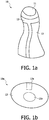
- FIG 1a shows a side view of an exemplary embodiment of a pawn 10 according to the invention.
- the pawn 10 comprises an insulating body 13 and two electrically conductive triggerable sub-parts 11 and 12.
- Figure 1b shows a bottom view of this pawn 10.
- the pawn 10 comprises a contact surface 10a for supporting the pawn on a board surface of the board.
- the contact surface 10a comprises two electrode contacts 11a and 12a.
- the triggerable sub-parts 11 and 12 are coupled to their respective electrode contacts 11a and 12a by an electrode.
- the electrode that couples the triggerable sub-part 11 on top of the pawn 10 to the central electrode contact 11a is buried in the mass of the pawn 10. This electrode is therefore well protected against damaging.
- the electrode that couples the triggerable sub-part 12 on the side of the pawn 10 to the outer electrode contact 12a runs along the surface of the pawn 10, which provides for a large triggerable area.
- the pawn 10 may have any possible shape and may comprise any number of triggerable sub parts.
- the electrodes can be made of bulk material wiring, or by conductive material like Indium Tin Oxide (ITO), copper, another metal or comparable materials, that offer transparent electrodes that can be structured in thin films. Alternatively, conducting polymers or carbon loaded materials may be used.
- ITO Indium Tin Oxide
- copper copper
- another metal or comparable materials that offer transparent electrodes that can be structured in thin films.
- conducting polymers or carbon loaded materials may be used.
- the triggerable sub-parts 11 and 12 are coupled to an input of an electronic circuit which may be buried in the mass of the pawn 10.
- the electronic circuit creates a trigger signal, which trigger signal comprises information about which triggerable sub-part 11, 12 was touched.
- the trigger signal may further comprise other information, such as how long the triggerable sub-part 11, 12 was touched, the time at which the triggerable sub-part 11, 12 was touched or an identification of the pawn 10 which the triggerable sub-part 11, 12 is a part of.
- the information about which sub-part 11, 12 was touched is encoded in the trigger signal, only one electrode is required for communicating the trigger signal to the board.
- the trigger signal may also be communicated to the board using other communication means.
- wireless communication means such as radio wave (e.g. Bluetooth) or infrared communication may be used for communicating the trigger signal to the board.
- radio wave e.g. Bluetooth
- infrared communication may be used for communicating the trigger signal to the board.
- FIG. 2 schematically shows a system 20 according to the invention.
- the system 20 comprises a game board 21 and a set of pawns 10 as described above.
- the game board 21 comprises a board surface 22 whereon the game is played.
- the board surface 22 may show a permanent layout according to the rules of a board game which the game board 21 is made for. Possibly, the board surface 22 comprises parts of which the appearance changes during the progress of the game.
- the board surface 22 is a surface of an LCD-screen or other type of monitor, which makes it possible to display an unlimited amount of different layouts on the board surface 22. On such a game board 21 an unlimited amount of different board games may be played.
- the layout of the board surface 22 may also change during the game for indicating a change of the game situation.
- Changes of the game situation may also be indicated by a sound from the speakers 23, by a text or score displayed on a text display 25 or by any other means capable of providing information.
- pawns 10 may be placed on or taken from the board surface 22 or may be moved from one position on the board surface 22 to another.
- the game board 21 further comprises a receiving unit 26 for receiving trigger signals from the pawns 10.
- the receiving unit 26 therefore has to communicate with a communication unit of the pawn 10. If, for example, the trigger signals are provided via the electrode contacts 11a, 12a at the contact surface of the pawn 10, the receiving unit 26 has to be electrically coupled to the board surface 22. If the trigger signals are provided via Bluetooth or infrared communication, the receiving unit 26 has to comprise a Bluetooth or infrared receiver respectively. Alternatively, the receiving unit 26 is connected to an array of electrodes for localization of contacts with the pawn.
- a processor 27 in the game board 21 has a processor input coupled to the receiving unit 26 and a processor output coupled to a device, such as the LCD-screen, the text display 25 and/or the speakers 23, for presenting the game situation.
- a device such as the LCD-screen, the text display 25 and/or the speakers 23, for presenting the game situation.
- the processor 27 determines the new game situation which is changed by the touching of one of the triggerable sub-parts 11, 12.
- the new game situation is determined from the previous game situation and the received trigger signal.
- the processor 27 sends instructions to the LCD-screen, text display 25 and/or speakers 23 for enabling the presentation of the changed situation.
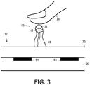
- Figure 3 shows a pawn 10 and part of a board according to the invention.
- Figure 3 further shows a user's finger, touching the triggerable sub-part 11 on top of the pawn 10.
- the finger 31 brings the triggerable sub-part 11, the electrode and the electrode contact 11a to the same potential as the body of the user.
- the electrode contact 11a contacts the board surface 22
- the variation of the potential is detected by the elements 33 which are embedded in the board 21.
- the embedding of an array of elements 33 in the board allows localizing the point of contact with high accuracy.
- FIG 4 shows a block diagram of the system according to the invention.
- the system comprises a board 42 and at least one pawn 41.
- the pawn 41 comprises at least two separate triggerable sub-parts, of which only one triggerable sub-part 43 is shown in Figure 4 .
- the triggerable sub-part 43 may be an electrically conductive contact, a pressure sensor, a heat sensor, a button or any other type of sensitive contact, capable of sensing a touch by a user.
- a touch can be detected regardless of how it is performed.
- the user may, for example, touch the triggerable sub-part 43 with bare fingers, with gloves on or with an electrically conductive or insulating pointing device.
- a trigger signal is provided, which corresponds to the touched sub-part 43.
- the trigger signal may, for example, be an electric signal, a light signal or a radio signal.
- a different trigger signal is provided. Therefore it will be possible for the board 42 to differentiate between the touching of different sub-parts.
- the difference between two signals may, for example, be obtained by providing frequency modulated or phase modulated radio signals, by providing electric currents of different magnitude or by providing identical signals via different paths.
- the pawn 41 comprises a communication unit 44 for communicating the trigger signal to the board 42 when the triggerable sub-part 43 is touched.
- electrodes may be used, as described above with reference to Figure 1 and 3 .
- wireless communication techniques such as Bluetooth or infrared communication may be used.
- the pawn 41 may comprise an electronic circuit for creating and/or processing the trigger signals and for sending the trigger signals to the board 42.
- the electronic circuit may convert the original signals coming from the triggerable sub-parts to other signals for sending to the board 42.
- the converted signals may also comprise additional information like, for example, an identity code of the pawn or a time at which the touch is detected.
- the pawn 41 comprises a power unit or a unit for receiving power from an external power source.
- the board 42 comprises a receiving unit 45 for receiving the trigger signal from the communication unit 44.
- the receiving unit 45 and the processor may be integrated in the game board 42 or may be present in a separate unit which is coupled to the board 42.
- the receiving unit 45 may also be part of or coupled to a personal computer which is coupled to the board 42.
- a processor of the personal computer may be used for processing the trigger signal and changing the situation and an output of the personal computer is coupled to the board 42 for providing the changed situation to the presentation means 47 for presenting the situation to the user.
- Figure 5a, 5b and 5c show three orientations of a pawn comprising a pattern of electrode contacts 14, 15, 16 at the contact surface 10a.
- the pattern is rotation asymmetric.
- Figure 5a one random orientation of the pawn is shown.
- Figure 5b and 5c show that it is not possible to rotate and/or replace the pawn without changing the orientation of the pattern of electrodes 14, 15, 16 relative to the board.
- the orientation of the pawn can be determined.
- Figure 6a shows a front view of an exemplary embodiment of a pawn 60 according to the invention.
- This pawn 60 is preferably used for a board game and represents a warrior.
- the pawn 60 comprises three triggerable sub-parts with the shape of a head 61, a shield 62 or a sword 63. These triggerable sub-parts are coupled to their respective electrode contacts 61a, 62a, 63a.
- a user may, for example, choose to let the character attack an unfriendly character of another player by touching the sword 63, fend off an attack by touching the shield 62 or try to negotiate by touching the helmet 61.
- Figure 6b shows a bottom view of the exemplary embodiment of the pawn 60 shown in Figure 6a . The bottom view shows a possible arrangement of the electrode contacts 61a, 62a and 63a.
- Figure 7 shows an exemplary embodiment of a pawn 60 according to the invention, comprising a switch 70.
- the switch 70 has two states: 'sword up' 70a and 'sword down' 70b.
- the switch 70 When the switch 70 is in a 'sword up'-state the user may, for example, choose to let the character attack an unfriendly character of another player by touching the sword 70a, fend off an attack by touching the shield 62 or try to negotiate by touching the helmet 61.
- the switch 70 is in a 'sword-down'-state 70b, the attack option is disabled and the user should choose between negotiating and shielding.
- the disabling may, for example be obtained by interrupting the electrode which extends from the triggerable sub-part 70 to the electrode contact at the support surface of the pawn 60.
Landscapes
- Engineering & Computer Science (AREA)
- Multimedia (AREA)
- Switches That Are Operated By Magnetic Or Electric Fields (AREA)
- Position Input By Displaying (AREA)
- User Interface Of Digital Computer (AREA)
- Nozzles (AREA)
Claims (12)
- Pion (10) à utiliser sur un plateau (21) et comprenant :- une surface de support (10a) pour supporter le pion (10) sur une surface de plateau (22) du plateau (21),- un corps isolant (5),- au moins deux sous-parties séparées déclenchables, électriquement conductrices (11, 12), moyennant quoi lors de l'utilisation, au toucher de chacune des au moins deux sous-parties séparées déclenchables (11, 12) par un utilisateur, un premier et un deuxième signal de déclenchement électrique sont respectivement fournis, le premier et le deuxième signal de déclenchement électrique pouvant être différenciés l'un de l'autre, et- un moyen de communication pour communiquer le premier et le deuxième signal de déclenchement électrique au plateau (21), le moyen de communication comprenant au moins une électrode, s'étendant depuis un contact d'électrode (11a, 12a) au niveau de la surface de support (10a) jusqu'à l'une des sous-parties déclenchables (11, 12), moyennant quoi lors de l'utilisation, au toucher de ladite sous-partie déclenchable (11, 12), le signal électrique correspondant entre ladite une des sous-parties déclenchables (11, 12) et la surface de plateau (22) est conduit, changeant de ce fait une charge électrique sur la surface de plateau (22).
- Pion (10) selon la revendication 1, dans lequel les contacts d'électrode (11a, 12a) au niveau de la surface de support (10a) forment un motif géométrique pour identifier le pion (10).
- Pion (10) selon la revendication 2, dans lequel le motif est asymétrique en rotation.
- Pion (10) selon la revendication 1, comprenant en outre un commutateur (70) pour désactiver ou activer la conduction du signal électrique entre ladite une des sous-parties déclenchables et la surface de plateau (22).
- Pion (10) selon la revendication 1, comprenant en outre un circuit électronique, lequel circuit électronique comprend :- une entrée couplée aux au moins deux sous-parties déclenchables (11, 12), et- une sortie pour fournir le premier et le deuxième signal de déclenchement électrique au moyen de communication.
- Pion (10) selon la revendication 5 dans lequel le moyen de communication comprend également un moyen de communication sans fil pour communiquer le premier et le deuxième signal de déclenchement électrique au plateau (21).
- Pion (10) selon la revendication 1 étant agencé pour fournir un troisième signal de déclenchement électrique lors d'un toucher simultané des deux sous-parties déclenchables (11, 12) par un utilisateur, le troisième signal de déclenchement électrique pouvant être différencié du premier et du deuxième signal de déclenchement électrique.
- Système (20) comprenant un plateau (21) et au moins un pion selon la revendication 1, le système comprenant en outre :- des moyens de présentation (22, 23, 25) pour présenter une situation à l'utilisateur,- un moyen de réception (26) pour recevoir le premier et le deuxième signal de déclenchement électrique, et- un processeur (27) comprenant une entrée de processeur et une sortie de processeur, l'entrée de processeur étant couplée au moyen de réception (26), la sortie de processeur étant couplée aux moyens de présentation (22, 23, 25) pour changer la situation en réponse au premier et au deuxième signal de déclenchement électrique.
- Système (20) selon la revendication 8, dans lequel le plateau (21) est un plateau de jeu et la situation est une situation de jeu.
- Système (20) selon la revendication 8, dans lequel les contacts d'électrode (11a, 12a) au niveau de la surface de support (10a) forment un motif géométrique pour identifier le pion (10), et le processeur (27) sert à reconnaître le motif géométrique.
- Système (20) selon la revendication 10, dans lequel le processeur (27) sert en outre à déterminer une position du motif par rapport au plateau (21).
- Système (20) selon la revendication 8, dans lequel le processeur (27) sert en outre à déterminer une orientation du motif par rapport au plateau (21).
Priority Applications (1)
| Application Number | Priority Date | Filing Date | Title |
|---|---|---|---|
| EP06710771.4A EP1850928B1 (fr) | 2005-02-02 | 2006-01-27 | Pion a sous-pieces declenchables |
Applications Claiming Priority (3)
| Application Number | Priority Date | Filing Date | Title |
|---|---|---|---|
| EP05100700 | 2005-02-02 | ||
| EP06710771.4A EP1850928B1 (fr) | 2005-02-02 | 2006-01-27 | Pion a sous-pieces declenchables |
| PCT/IB2006/050300 WO2006082547A2 (fr) | 2005-02-02 | 2006-01-27 | Pion a sous-pieces declenchables |
Publications (2)
| Publication Number | Publication Date |
|---|---|
| EP1850928A2 EP1850928A2 (fr) | 2007-11-07 |
| EP1850928B1 true EP1850928B1 (fr) | 2017-11-08 |
Family
ID=36658669
Family Applications (1)
| Application Number | Title | Priority Date | Filing Date |
|---|---|---|---|
| EP06710771.4A Expired - Lifetime EP1850928B1 (fr) | 2005-02-02 | 2006-01-27 | Pion a sous-pieces declenchables |
Country Status (5)
| Country | Link |
|---|---|
| US (1) | US8568216B2 (fr) |
| EP (1) | EP1850928B1 (fr) |
| JP (1) | JP5009814B2 (fr) |
| CN (1) | CN101111295B (fr) |
| WO (1) | WO2006082547A2 (fr) |
Families Citing this family (43)
| Publication number | Priority date | Publication date | Assignee | Title |
|---|---|---|---|---|
| EP2077142A1 (fr) | 2008-01-04 | 2009-07-08 | Koninklijke Philips Electronics N.V. | Objet, procédé et système pour la transmission d'informations à un utilisateur |
| US8816961B2 (en) | 2008-04-01 | 2014-08-26 | Koninklijke Philips N.V. | Pointing device for use on an interactive surface |
| JP6043482B2 (ja) * | 2008-06-03 | 2016-12-14 | トウィードルテック リミテッド ライアビリティ カンパニー | インテリジェントボードゲームシステム、ゲーム駒、インテリジェントボードゲームシステムを操作する方法、インテリジェントボードゲームをプレイする方法 |
| JP5577202B2 (ja) * | 2009-11-30 | 2014-08-20 | 高司 山本 | 情報処理装置用の駆動装置及びマルチタッチ機能を利用した情報処理システム |
| MX2012010864A (es) * | 2010-03-22 | 2013-04-03 | Mattel Inc | Dispositivo electronico y la entrada y salida de datos. |
| US9274641B2 (en) | 2010-07-08 | 2016-03-01 | Disney Enterprises, Inc. | Game pieces for use with touch screen devices and related methods |
| US20120007808A1 (en) * | 2010-07-08 | 2012-01-12 | Disney Enterprises, Inc. | Interactive game pieces using touch screen devices for toy play |
| GB2482559A (en) * | 2010-08-06 | 2012-02-08 | Disruptive Ltd | Interacting with touch screen devices via a multi touch device. |
| FR2970352B1 (fr) * | 2011-01-12 | 2016-02-05 | Jean Etienne Mineur | Dispositif de reconnaissance de grille picot statique conductive sur ecran capacitif |
| FR2970353B1 (fr) * | 2011-01-12 | 2013-09-27 | Jean Etienne Mineur | Pion a semelle picot emetteur de bit sur ecran capacitif |
| US20120194457A1 (en) * | 2011-01-28 | 2012-08-02 | Bruce Cannon | Identifiable Object and a System for Identifying an Object by an Electronic Device |
| FR2973530B1 (fr) * | 2011-04-01 | 2013-08-09 | Editions Volumiques | Dispositif interactif a fibre optique conductrice monte sur figurine |
| US20140024287A1 (en) * | 2011-02-09 | 2014-01-23 | Jean Etienne Mineur | Figurine that interacts with a capacitive screen in an illuminated manner |
| FR2971166A1 (fr) * | 2011-02-09 | 2012-08-10 | Editions Volumiques | Figurine materielle physique lumineuse sur ecran numerique |
| US20120249430A1 (en) * | 2011-03-31 | 2012-10-04 | Oster David Phillip | Multi-Touch Screen Recognition of Interactive Objects, and Application Thereof |
| FR2976187A1 (fr) * | 2011-06-09 | 2012-12-14 | Editions Volumiques | Plateau de jeu cooperant avec ecran de tablette numerique. |
| GB2493139A (en) * | 2011-07-15 | 2013-01-30 | Blue Sky Designs Ltd | A handheld device with contact member to contact a touch screen |
| FR2985821B1 (fr) * | 2012-01-17 | 2015-07-10 | Editions Volumiques | Chambre d'illusion optique pour figurine cooperant avec terminal numerique |
| CA2863069C (fr) * | 2012-02-02 | 2020-03-10 | Smart Technologies Ulc | Systeme d'entree interactif et procede de detection d'objets |
| WO2013122798A1 (fr) | 2012-02-17 | 2013-08-22 | Technology One, Inc. | Ensemble de plaque de base pour utilisation avec des pièces de jeu |
| US9372568B2 (en) * | 2012-03-05 | 2016-06-21 | Beijing Lenovo Software Ltd. | Method, device and system for interacting |
| US9492762B2 (en) * | 2012-05-08 | 2016-11-15 | Funfare, Llc | Sensor configuration for toy |
| FI124483B (en) * | 2012-05-28 | 2014-09-30 | Frozenbyte Oy | Identification of the object |
| GB2512266B (en) * | 2012-10-02 | 2016-04-13 | Interactive Product Solutions Ltd | Means of providing a three dimentional touch screen interface device using conventional or printed materials |
| WO2015113365A1 (fr) * | 2014-01-30 | 2015-08-06 | Zheng Shi | Système et procédé de reconnaissance d'id, d'orientation et de position d'un objet par rapport à une surface interactive |
| US20140327645A1 (en) * | 2013-05-06 | 2014-11-06 | Nokia Corporation | Touchscreen accessory attachment |
| US10114486B2 (en) * | 2013-09-19 | 2018-10-30 | Change Healthcare Holdings, Llc | Method and apparatus for providing touch input via a touch sensitive surface utilizing a support object |
| CN105592897A (zh) * | 2014-01-30 | 2016-05-18 | 施政 | 用连续电容传感识别物体的系统和方法 |
| WO2015113395A1 (fr) * | 2014-01-30 | 2015-08-06 | Zheng Shi | Système et procédé permettant de diriger un objet mobile sur une surface interactive |
| US10599831B2 (en) | 2014-02-07 | 2020-03-24 | Snowshoefood Inc. | Increased security method for hardware-tool-based authentication |
| US10105589B2 (en) | 2014-03-06 | 2018-10-23 | Zheng Shi | System and method for directing an object to move on an interactive surface through a defined path |
| JP6923995B2 (ja) * | 2014-09-24 | 2021-08-25 | 任天堂株式会社 | 情報処理システム、情報処理装置、情報処理プログラム、および情報処理方法 |
| EP3001288B1 (fr) * | 2014-09-24 | 2018-10-31 | Nintendo Co., Ltd. | Systeme de traitement d'informations, appareil de traitement d'informations, programme de traitement d'informations et procede de traitement d'informations |
| DK3253467T3 (da) | 2015-02-04 | 2019-08-26 | Lego As | Legetøjssystem omfattende legetøjselementer, som kan detekteres af en behandlingsindretning |
| JP5771761B1 (ja) * | 2015-02-09 | 2015-09-02 | 淳一 榎本 | 接触検出から取得したアドレスを用いた通信の可能な情報通信システム、プログラム及び方法 |
| US10026333B2 (en) | 2015-02-24 | 2018-07-17 | Alexandra Rose HUFFMAN | Educational balancing game |
| WO2017115437A1 (fr) * | 2015-12-28 | 2017-07-06 | 泰和 西尾 | Système d'entrée |
| JP6152211B1 (ja) * | 2016-10-07 | 2017-06-21 | 株式会社Cygames | ボードゲームシステム等 |
| AU2018310872B2 (en) * | 2017-07-03 | 2021-04-01 | Lai Wa WONG | Device having multi-touch applications |
| US11194464B1 (en) * | 2017-11-30 | 2021-12-07 | Amazon Technologies, Inc. | Display control using objects |
| JP6490288B1 (ja) * | 2018-08-31 | 2019-03-27 | 株式会社Cygames | 電子装置、システム、方法及びプログラム |
| CN111214823B (zh) * | 2020-01-09 | 2020-09-01 | 周柏香 | 执子姿势训练用围棋棋子及其使用方法 |
| US11517812B2 (en) * | 2021-02-19 | 2022-12-06 | Blok Party, Inc. | Application of RFID gamepieces for a gaming console |
Citations (1)
| Publication number | Priority date | Publication date | Assignee | Title |
|---|---|---|---|---|
| WO2002021432A1 (fr) * | 2000-09-06 | 2002-03-14 | Innovision Research & Technology Ltd | Appareil de détermination de position |
Family Cites Families (21)
| Publication number | Priority date | Publication date | Assignee | Title |
|---|---|---|---|---|
| US680746A (en) * | 1901-06-14 | 1901-08-20 | Thomas L Tremblay | Cooking apparatus. |
| US3893671A (en) * | 1974-09-03 | 1975-07-08 | Robert C Gardner | Fiber optic chessboard |
| US4391447A (en) * | 1980-11-20 | 1983-07-05 | Raymond Dudley | Electronic chess game |
| JPS58105771A (ja) * | 1981-12-16 | 1983-06-23 | 松下電器産業株式会社 | ゲ−ムボ−ドにおける駒の検出装置 |
| US4545582A (en) * | 1983-02-25 | 1985-10-08 | Andrews Walter H | Translucent electronic board game with magnetic pawn |
| DE69030846T2 (de) | 1989-07-28 | 1998-01-22 | Canon Kk | Bildherstellungsapparat |
| GB8920204D0 (en) * | 1989-09-07 | 1989-10-18 | Saitek Ltd | Sensory games |
| DE68901599D1 (de) * | 1989-10-25 | 1992-06-25 | Saitek Ltd | Elektronisches spielgeraet. |
| JPH03222977A (ja) * | 1990-01-30 | 1991-10-01 | I C Denshi Kogyo Kk | オセロゲーム〔登録商標〕装置 |
| US5190285A (en) * | 1991-09-30 | 1993-03-02 | At&T Bell Laboratories | Electronic game having intelligent game pieces |
| US5462281A (en) * | 1994-06-30 | 1995-10-31 | Gaito; Andre A. | Electrified board game |
| CA2196048A1 (fr) * | 1994-07-28 | 1996-02-08 | Super Dimension Inc. | Table de jeu avec ordinateur |
| US5823782A (en) * | 1995-12-29 | 1998-10-20 | Tinkers & Chance | Character recognition educational system |
| DE29611937U1 (de) * | 1996-07-09 | 1996-11-14 | Meyer, Werner, 75417 Mühlacker | Programmierbare Schachfigur, die mit einem Zufallsgenerator ausgestattet ist |
| CN2321495Y (zh) * | 1997-12-29 | 1999-06-02 | 潘友耕 | 棋盘自动计时系统 |
| GB2344257A (en) * | 1998-11-26 | 2000-05-31 | Innovision Research And Techno | Data communication apparatus and board game |
| WO2001015059A2 (fr) * | 1999-08-24 | 2001-03-01 | Gamalong Ltd. | Systeme et procede de detection de l'emplacement d'un objet physique place sur un ecran |
| US6443796B1 (en) * | 2000-06-19 | 2002-09-03 | Judith Ann Shackelford | Smart blocks |
| JP3901163B2 (ja) * | 2001-02-02 | 2007-04-04 | 株式会社セガ | カードゲーム装置 |
| FR2848871B1 (fr) * | 2002-12-18 | 2009-09-18 | Sylvius | Element pour jeu, tel qu'un pion, et systeme de jeu associe |
| DE602005015606D1 (de) | 2004-09-21 | 2009-09-03 | Koninkl Philips Electronics Nv | Spielbrett, spielfigur und system zum spielen von brettspielen |
-
2006
- 2006-01-27 EP EP06710771.4A patent/EP1850928B1/fr not_active Expired - Lifetime
- 2006-01-27 JP JP2007553758A patent/JP5009814B2/ja not_active Expired - Fee Related
- 2006-01-27 WO PCT/IB2006/050300 patent/WO2006082547A2/fr not_active Ceased
- 2006-01-27 US US11/815,017 patent/US8568216B2/en not_active Expired - Fee Related
- 2006-01-27 CN CN2006800038587A patent/CN101111295B/zh not_active Expired - Fee Related
Patent Citations (1)
| Publication number | Priority date | Publication date | Assignee | Title |
|---|---|---|---|---|
| WO2002021432A1 (fr) * | 2000-09-06 | 2002-03-14 | Innovision Research & Technology Ltd | Appareil de détermination de position |
Also Published As
| Publication number | Publication date |
|---|---|
| WO2006082547A3 (fr) | 2007-03-01 |
| CN101111295A (zh) | 2008-01-23 |
| US8568216B2 (en) | 2013-10-29 |
| JP5009814B2 (ja) | 2012-08-22 |
| CN101111295B (zh) | 2010-06-23 |
| EP1850928A2 (fr) | 2007-11-07 |
| US20080161086A1 (en) | 2008-07-03 |
| JP2008528226A (ja) | 2008-07-31 |
| WO2006082547A2 (fr) | 2006-08-10 |
Similar Documents
| Publication | Publication Date | Title |
|---|---|---|
| US8568216B2 (en) | Pawn with triggerable sub parts | |
| JP4810573B2 (ja) | 対象物情報検出のための装置およびそれを使用する方法 | |
| JP4909996B2 (ja) | 操作方向検出装置 | |
| CN105242772B (zh) | 提供静电触觉效果的表面元件的系统和方法 | |
| EP2405330B1 (fr) | Pièces de jeu interactif utilisant des dispositifs à écran tactile pour jouer avec des jouets | |
| US6572108B1 (en) | Game pad controller | |
| JP7455832B2 (ja) | 取り外し可能なオーバーレイ付きハンドヘルドコントローラ | |
| US9925456B1 (en) | Single manipulatable physical and virtual game assembly | |
| WO2003007227A2 (fr) | Ecran tactile a sources de pression selectives | |
| WO2012017205A2 (fr) | Interaction avec des dispositifs à écran tactile | |
| WO2017202921A1 (fr) | Appareil et procédé pour communiquer la présence d'un objet à un ordinateur | |
| KR200429458Y1 (ko) | 좌표지정장치 및 이를 장착한 게임용 조정기 | |
| WO2014047675A1 (fr) | Jeu interactif | |
| EP3723882A1 (fr) | Système de jeu d'arcade domestique | |
| JP6770103B2 (ja) | 近接感知を備えた入力デバイスにおける指追跡 | |
| JP2013538077A (ja) | ゲームピースの静電容量検知と識別とを組み込んだ双方向ゲームボードシステム | |
| AU2002345834A1 (en) | Touch screen with selective touch sources |
Legal Events
| Date | Code | Title | Description |
|---|---|---|---|
| PUAI | Public reference made under article 153(3) epc to a published international application that has entered the european phase |
Free format text: ORIGINAL CODE: 0009012 |
|
| 17P | Request for examination filed |
Effective date: 20070903 |
|
| AK | Designated contracting states |
Kind code of ref document: A2 Designated state(s): AT BE BG CH CY CZ DE DK EE ES FI FR GB GR HU IE IS IT LI LT LU LV MC NL PL PT RO SE SI SK TR |
|
| DAX | Request for extension of the european patent (deleted) | ||
| 17Q | First examination report despatched |
Effective date: 20121213 |
|
| RAP1 | Party data changed (applicant data changed or rights of an application transferred) |
Owner name: KONINKLIJKE PHILIPS N.V. |
|
| GRAP | Despatch of communication of intention to grant a patent |
Free format text: ORIGINAL CODE: EPIDOSNIGR1 |
|
| INTG | Intention to grant announced |
Effective date: 20170608 |
|
| RIN1 | Information on inventor provided before grant (corrected) |
Inventor name: BERGMAN, ANTHONIE, H. Inventor name: DECRE, MICHEL, M., J. Inventor name: CORTENRAAD, HUBERTUS, M., R. |
|
| GRAS | Grant fee paid |
Free format text: ORIGINAL CODE: EPIDOSNIGR3 |
|
| GRAA | (expected) grant |
Free format text: ORIGINAL CODE: 0009210 |
|
| AK | Designated contracting states |
Kind code of ref document: B1 Designated state(s): AT BE BG CH CY CZ DE DK EE ES FI FR GB GR HU IE IS IT LI LT LU LV MC NL PL PT RO SE SI SK TR |
|
| REG | Reference to a national code |
Ref country code: GB Ref legal event code: FG4D |
|
| REG | Reference to a national code |
Ref country code: AT Ref legal event code: REF Ref document number: 943599 Country of ref document: AT Kind code of ref document: T Effective date: 20171115 Ref country code: CH Ref legal event code: EP |
|
| REG | Reference to a national code |
Ref country code: IE Ref legal event code: FG4D |
|
| REG | Reference to a national code |
Ref country code: DE Ref legal event code: R096 Ref document number: 602006054039 Country of ref document: DE |
|
| REG | Reference to a national code |
Ref country code: FR Ref legal event code: PLFP Year of fee payment: 13 |
|
| REG | Reference to a national code |
Ref country code: NL Ref legal event code: MP Effective date: 20171108 |
|
| REG | Reference to a national code |
Ref country code: LT Ref legal event code: MG4D |
|
| REG | Reference to a national code |
Ref country code: AT Ref legal event code: MK05 Ref document number: 943599 Country of ref document: AT Kind code of ref document: T Effective date: 20171108 |
|
| PG25 | Lapsed in a contracting state [announced via postgrant information from national office to epo] |
Ref country code: FI Free format text: LAPSE BECAUSE OF FAILURE TO SUBMIT A TRANSLATION OF THE DESCRIPTION OR TO PAY THE FEE WITHIN THE PRESCRIBED TIME-LIMIT Effective date: 20171108 Ref country code: NL Free format text: LAPSE BECAUSE OF FAILURE TO SUBMIT A TRANSLATION OF THE DESCRIPTION OR TO PAY THE FEE WITHIN THE PRESCRIBED TIME-LIMIT Effective date: 20171108 Ref country code: LT Free format text: LAPSE BECAUSE OF FAILURE TO SUBMIT A TRANSLATION OF THE DESCRIPTION OR TO PAY THE FEE WITHIN THE PRESCRIBED TIME-LIMIT Effective date: 20171108 Ref country code: ES Free format text: LAPSE BECAUSE OF FAILURE TO SUBMIT A TRANSLATION OF THE DESCRIPTION OR TO PAY THE FEE WITHIN THE PRESCRIBED TIME-LIMIT Effective date: 20171108 Ref country code: SE Free format text: LAPSE BECAUSE OF FAILURE TO SUBMIT A TRANSLATION OF THE DESCRIPTION OR TO PAY THE FEE WITHIN THE PRESCRIBED TIME-LIMIT Effective date: 20171108 |
|
| PG25 | Lapsed in a contracting state [announced via postgrant information from national office to epo] |
Ref country code: AT Free format text: LAPSE BECAUSE OF FAILURE TO SUBMIT A TRANSLATION OF THE DESCRIPTION OR TO PAY THE FEE WITHIN THE PRESCRIBED TIME-LIMIT Effective date: 20171108 Ref country code: IS Free format text: LAPSE BECAUSE OF FAILURE TO SUBMIT A TRANSLATION OF THE DESCRIPTION OR TO PAY THE FEE WITHIN THE PRESCRIBED TIME-LIMIT Effective date: 20180308 Ref country code: GR Free format text: LAPSE BECAUSE OF FAILURE TO SUBMIT A TRANSLATION OF THE DESCRIPTION OR TO PAY THE FEE WITHIN THE PRESCRIBED TIME-LIMIT Effective date: 20180209 Ref country code: LV Free format text: LAPSE BECAUSE OF FAILURE TO SUBMIT A TRANSLATION OF THE DESCRIPTION OR TO PAY THE FEE WITHIN THE PRESCRIBED TIME-LIMIT Effective date: 20171108 Ref country code: BG Free format text: LAPSE BECAUSE OF FAILURE TO SUBMIT A TRANSLATION OF THE DESCRIPTION OR TO PAY THE FEE WITHIN THE PRESCRIBED TIME-LIMIT Effective date: 20180208 |
|
| PG25 | Lapsed in a contracting state [announced via postgrant information from national office to epo] |
Ref country code: CY Free format text: LAPSE BECAUSE OF FAILURE TO SUBMIT A TRANSLATION OF THE DESCRIPTION OR TO PAY THE FEE WITHIN THE PRESCRIBED TIME-LIMIT Effective date: 20171108 Ref country code: EE Free format text: LAPSE BECAUSE OF FAILURE TO SUBMIT A TRANSLATION OF THE DESCRIPTION OR TO PAY THE FEE WITHIN THE PRESCRIBED TIME-LIMIT Effective date: 20171108 Ref country code: DK Free format text: LAPSE BECAUSE OF FAILURE TO SUBMIT A TRANSLATION OF THE DESCRIPTION OR TO PAY THE FEE WITHIN THE PRESCRIBED TIME-LIMIT Effective date: 20171108 Ref country code: CZ Free format text: LAPSE BECAUSE OF FAILURE TO SUBMIT A TRANSLATION OF THE DESCRIPTION OR TO PAY THE FEE WITHIN THE PRESCRIBED TIME-LIMIT Effective date: 20171108 Ref country code: SK Free format text: LAPSE BECAUSE OF FAILURE TO SUBMIT A TRANSLATION OF THE DESCRIPTION OR TO PAY THE FEE WITHIN THE PRESCRIBED TIME-LIMIT Effective date: 20171108 |
|
| REG | Reference to a national code |
Ref country code: DE Ref legal event code: R097 Ref document number: 602006054039 Country of ref document: DE |
|
| PG25 | Lapsed in a contracting state [announced via postgrant information from national office to epo] |
Ref country code: RO Free format text: LAPSE BECAUSE OF FAILURE TO SUBMIT A TRANSLATION OF THE DESCRIPTION OR TO PAY THE FEE WITHIN THE PRESCRIBED TIME-LIMIT Effective date: 20171108 Ref country code: PL Free format text: LAPSE BECAUSE OF FAILURE TO SUBMIT A TRANSLATION OF THE DESCRIPTION OR TO PAY THE FEE WITHIN THE PRESCRIBED TIME-LIMIT Effective date: 20171108 Ref country code: IT Free format text: LAPSE BECAUSE OF FAILURE TO SUBMIT A TRANSLATION OF THE DESCRIPTION OR TO PAY THE FEE WITHIN THE PRESCRIBED TIME-LIMIT Effective date: 20171108 |
|
| REG | Reference to a national code |
Ref country code: CH Ref legal event code: PL |
|
| PLBE | No opposition filed within time limit |
Free format text: ORIGINAL CODE: 0009261 |
|
| STAA | Information on the status of an ep patent application or granted ep patent |
Free format text: STATUS: NO OPPOSITION FILED WITHIN TIME LIMIT |
|
| 26N | No opposition filed |
Effective date: 20180809 |
|
| PG25 | Lapsed in a contracting state [announced via postgrant information from national office to epo] |
Ref country code: LU Free format text: LAPSE BECAUSE OF NON-PAYMENT OF DUE FEES Effective date: 20180127 |
|
| REG | Reference to a national code |
Ref country code: IE Ref legal event code: MM4A |
|
| REG | Reference to a national code |
Ref country code: BE Ref legal event code: MM Effective date: 20180131 |
|
| PG25 | Lapsed in a contracting state [announced via postgrant information from national office to epo] |
Ref country code: CH Free format text: LAPSE BECAUSE OF NON-PAYMENT OF DUE FEES Effective date: 20180131 Ref country code: LI Free format text: LAPSE BECAUSE OF NON-PAYMENT OF DUE FEES Effective date: 20180131 Ref country code: BE Free format text: LAPSE BECAUSE OF NON-PAYMENT OF DUE FEES Effective date: 20180131 Ref country code: SI Free format text: LAPSE BECAUSE OF FAILURE TO SUBMIT A TRANSLATION OF THE DESCRIPTION OR TO PAY THE FEE WITHIN THE PRESCRIBED TIME-LIMIT Effective date: 20171108 |
|
| PG25 | Lapsed in a contracting state [announced via postgrant information from national office to epo] |
Ref country code: IE Free format text: LAPSE BECAUSE OF NON-PAYMENT OF DUE FEES Effective date: 20180127 |
|
| PG25 | Lapsed in a contracting state [announced via postgrant information from national office to epo] |
Ref country code: MC Free format text: LAPSE BECAUSE OF FAILURE TO SUBMIT A TRANSLATION OF THE DESCRIPTION OR TO PAY THE FEE WITHIN THE PRESCRIBED TIME-LIMIT Effective date: 20171108 |
|
| PG25 | Lapsed in a contracting state [announced via postgrant information from national office to epo] |
Ref country code: TR Free format text: LAPSE BECAUSE OF FAILURE TO SUBMIT A TRANSLATION OF THE DESCRIPTION OR TO PAY THE FEE WITHIN THE PRESCRIBED TIME-LIMIT Effective date: 20171108 |
|
| PGFP | Annual fee paid to national office [announced via postgrant information from national office to epo] |
Ref country code: GB Payment date: 20200129 Year of fee payment: 15 Ref country code: DE Payment date: 20200131 Year of fee payment: 15 |
|
| PG25 | Lapsed in a contracting state [announced via postgrant information from national office to epo] |
Ref country code: PT Free format text: LAPSE BECAUSE OF FAILURE TO SUBMIT A TRANSLATION OF THE DESCRIPTION OR TO PAY THE FEE WITHIN THE PRESCRIBED TIME-LIMIT Effective date: 20171108 Ref country code: HU Free format text: LAPSE BECAUSE OF FAILURE TO SUBMIT A TRANSLATION OF THE DESCRIPTION OR TO PAY THE FEE WITHIN THE PRESCRIBED TIME-LIMIT; INVALID AB INITIO Effective date: 20060127 |
|
| PGFP | Annual fee paid to national office [announced via postgrant information from national office to epo] |
Ref country code: FR Payment date: 20200128 Year of fee payment: 15 |
|
| REG | Reference to a national code |
Ref country code: DE Ref legal event code: R119 Ref document number: 602006054039 Country of ref document: DE |
|
| GBPC | Gb: european patent ceased through non-payment of renewal fee |
Effective date: 20210127 |
|
| PG25 | Lapsed in a contracting state [announced via postgrant information from national office to epo] |
Ref country code: FR Free format text: LAPSE BECAUSE OF NON-PAYMENT OF DUE FEES Effective date: 20210131 |
|
| PG25 | Lapsed in a contracting state [announced via postgrant information from national office to epo] |
Ref country code: DE Free format text: LAPSE BECAUSE OF NON-PAYMENT OF DUE FEES Effective date: 20210803 Ref country code: GB Free format text: LAPSE BECAUSE OF NON-PAYMENT OF DUE FEES Effective date: 20210127 |