EP1851733B1 - Commande sequentielle pour un distributeur automatique - Google Patents
Commande sequentielle pour un distributeur automatique Download PDFInfo
- Publication number
- EP1851733B1 EP1851733B1 EP05798495A EP05798495A EP1851733B1 EP 1851733 B1 EP1851733 B1 EP 1851733B1 EP 05798495 A EP05798495 A EP 05798495A EP 05798495 A EP05798495 A EP 05798495A EP 1851733 B1 EP1851733 B1 EP 1851733B1
- Authority
- EP
- European Patent Office
- Prior art keywords
- merchandise
- removal
- vending machine
- removal trough
- compartment
- Prior art date
- Legal status (The legal status is an assumption and is not a legal conclusion. Google has not performed a legal analysis and makes no representation as to the accuracy of the status listed.)
- Expired - Lifetime
Links
Images




Classifications
-
- G—PHYSICS
- G07—CHECKING-DEVICES
- G07F—COIN-FREED OR LIKE APPARATUS
- G07F9/00—Details other than those peculiar to special kinds or types of apparatus
- G07F9/02—Devices for alarm or indication, e.g. when empty; Advertising arrangements in coin-freed apparatus
- G07F9/026—Devices for alarm or indication, e.g. when empty; Advertising arrangements in coin-freed apparatus for alarm, monitoring and auditing in vending machines or means for indication, e.g. when empty
-
- G—PHYSICS
- G07—CHECKING-DEVICES
- G07F—COIN-FREED OR LIKE APPARATUS
- G07F11/00—Coin-freed apparatus for dispensing, or the like, discrete articles
- G07F11/02—Coin-freed apparatus for dispensing, or the like, discrete articles from non-movable magazines
- G07F11/04—Coin-freed apparatus for dispensing, or the like, discrete articles from non-movable magazines in which magazines the articles are stored one vertically above the other
- G07F11/16—Delivery means
- G07F11/18—Recessed drawers
-
- G—PHYSICS
- G07—CHECKING-DEVICES
- G07F—COIN-FREED OR LIKE APPARATUS
- G07F11/00—Coin-freed apparatus for dispensing, or the like, discrete articles
- G07F11/02—Coin-freed apparatus for dispensing, or the like, discrete articles from non-movable magazines
- G07F11/36—Coin-freed apparatus for dispensing, or the like, discrete articles from non-movable magazines in which the magazines are of helical or spiral form
Definitions
- the invention relates to a vending machine with a plurality of stacked goods compartments, with output means for each product compartment, which each deliver a product from the goods compartment upon activation, with at least one transport device which is driven by drive means, and which the output of the output means by means of a removal tray transported to a removal position.
- the vending machine has an electronic control and storage unit for controlling the transport device in order to move the removal trough into a desired position in front of the respective activated goods compartment for receiving a product and subsequently into the goods issue area into the removal position for removal of the goods.
- the invention also relates to a method for operating a vending machine with a transport device.
- a vending machine for dispensing bottles or cans which has a plurality of superposed, inclined in the direction of a respectively associated transfer position goods compartments.
- a transport device moves a goods carrier. Of the The goods carrier can pick up goods from a goods compartment on request at the relevant transfer position. The goods are moved by means of the transport device to a transfer position in an upper section of the vending machine, where the goods roll into a removal compartment and ready for removal by a customer.
- the known vending machine is complicated.
- a vending machine with a transport device is disclosed.
- the transport device between the front wall of the vending machine and the goods compartments is arranged.
- a removal tray moves by means of the drive in a receiving position or target position in front of the respectively activated goods compartment and then in the goods issue area in the removal position.
- the front wall of such vending machines is e.g. formed as a door, and the transport device is fixed to the inner surface of the door by means of fastening elements.
- the transport device is particularly easy to access, such as to wait for them.
- the transport device typically contains transmission organs, on which the removal trough can be moved.
- the transmission organs form, for example, endless loops, which rotate over upper and lower deflecting members and drive members.
- the removal trough is attached to the transmission organs by means of fastening elements.
- the fastening elements, with which the removal trough is attached to the transmission organs can be displaceably guided in lateral guide rails.
- the transmission organs are designed as endless toothed belts. The transport of the removal trough is particularly precise with the guided in the lateral guide rails endless timing belt and feasible.
- the transport device includes the drive members, a drive shaft for driving the drive members, and a transport drive motor for driving the drive shaft and the deflecting members.
- the trained as a door front wall is hinged hinged in a fixed side wall of the machine.
- the front wall is usually designed as a viewing window, wherein a removal opening is arranged below the viewing window.
- the transmission organs, the deflection members, the drive members, the drive shaft and the drive are arranged behind the enclosure of the viewing window.
- the goods stored in the goods compartments are visible through the transparent front window from the outside and the drive elements are disguised due to their arrangement behind the enclosure of the viewing window with an outwardly-effective privacy screen.
- a customer is stimulated when looking at the vending machine to purchase the presented goods.
- the vending machines have locking means which hold a removal flap in a closed position in front of the removal opening and release the removal flap for opening only when the removal trough has reached the removal position in which the user can remove the goods through the removal opening from the removal trough. A theft of goods is thereby prevented during operation of the transport device.
- the object of the invention is to provide a vending machine whose structure and operation in the dispensing of goods is better than in the prior art.
- the object is achieved by a vending machine according to claim 1 and a method according to claim 11.
- the electronic control and storage unit of a vending machine is configured to determine and store a blockage position from which the removal trough is not moved in the direction of the desired position before reaching the desired position.
- a blockage position from which the removal trough is not moved in the direction of the desired position before reaching the desired position.
- conventional vending machines e.g. due to poor filling of the vending machines or subsequent slippage of the goods problems.
- the goods which are not in the correct position can block the removal trough during the movement to a setpoint position at which the removal trough is to take over a product from an activated goods compartment. This is e.g. then the case when a commodity, or the packaging of a commodity protrudes from a commodity compartment.
- Such a blockage in conventional vending machines causes the vending machine to go out of operation.
- the vending machine according to the invention is able to detect and store a blockage position by means of the electronic control and storage unit, which enables it to deal with a blockade in the present and in future sales transactions, without the vending machine according to the invention completely must go out of service.
- the sale of goods is still possible without the vending machine must be immediately subjected to extensive maintenance.
- the inventive vending machine has position control means for generating a position signal corresponding to an actual position of the removal trough.
- position control means for generating a position signal corresponding to an actual position of the removal trough.
- this can be done on the basis of the movements and the forces within the transport device and on the basis of the drive means.
- position control means in the vending machine which provide additional position information. This can be, for example, a light barrier or the like which transmits to the electronic control and storage unit whether a desired actual position has been reached.
- additional Position control means have the particular advantage that an independent position signal or an independent position information is provided, which is not derived only from the relative movements and forces of the transport device and the drive means.
- the electronic control and storage unit is designed such that the exceeding of a time limit is detected if the removal trough does not reach a predefined actual position during the approach of the desired position. As a result, an unacceptably high load on the transport device during blockage should be additionally prevented.
- the electronic control and storage unit has means not only to determine the blockage position itself, but one or more actual positions during the starting operation towards the target position. The electronic control and storage unit may then be e.g. derive the blockage position from these actual positions. If the start-up procedure for a target position with the removal trough is unsuccessful, then this is permitted only for a specific time interval or until a specific time limit has been exceeded.
- the electronic control and storage unit executes a special routine related to the presence of a blockage position.
- a special routine related to the presence of a blockage position.
- blockages can be determined earlier.
- the electronic control and storage unit performs at least a second attempt to start with the removal tray to reach the target position, if in the previous attempted start an exceeding of the time limit has been detected.
- the fact is taken into account that when starting a blockage with the removal trough under certain circumstances, this blockage is solved.
- a further attempt to start it may then be possible to reach the target position, ie the activated goods compartment, even if this was initially not possible in the first attempt.
- control and storage unit is configured such that the number of startup attempts is detected, in which an exceeding of the time limit was detected.
- the control and storage unit is configured such that the number of startup attempts is detected, in which an exceeding of the time limit was detected.
- a favorable number of start-up attempts may e.g. be determined empirically or result from practical considerations.
- control and storage unit terminates the sales process.
- This is a workable value, which does not mean waiting too long for the customer waiting for the goods to be delivered, but still makes a reasonable number of attempts to still spend the goods.
- the control and storage unit of a vending machine according to the invention may preferably take into account the blockage position determined and stored during a first sales attempt in a second, later sales attempt.
- This can e.g. It consists in the fact that goods from an unreachable goods compartment, which is behind a blockade, are no longer offered for sale. Goods that are still accessible with the removal tray despite the blockade, because they are before the blockade, but are still sold.
- a vending machine according to the invention is not completely shut down due to a blockade, but remains operational for at least some of the goods.
- the blockage position determined and stored during a first sales attempt is taken into account in a second, later sales attempt of a different kind.
- even goods that are located at a target position located behind the block are offered for sale if the goods can be handed over despite the blockade to the removal trough.
- One criterion may be that the goods are not damaged by a fall from a higher merchandise compartment in the removal tray.
- a product which is too sensitive or unsuitable for a transfer is not transferred according to this embodiment to the removal trough.
- This aspect of the invention makes it possible to sell even more of the goods despite the blockage position.
- An inventive vending machine preferably has a plurality of juxtaposed goods compartments, which together form a horizontal product compartment group.
- these merchandise groups may be spaced above each other and thus form a kind of floors.
- the removal trough can then preferably extend over the entire horizontal width of a department group, so that the goods of all goods belonging to a department group (to a floor) goods compartments can be delivered to the removal trough in a single desired position of the removal tray.
- the invention also relates to a method for operating a vending machine with a plurality of superimposed goods compartments with output means for each product compartment, which each release a product from the goods compartment upon activation, with at least one transport device, which the output of the output means by means of a removal tray to a removal position transported.
- the vending machine has an electronic control and storage unit for controlling the transport device to move the removal trough in a desired position in front of the respectively activated goods compartment for receiving a product and then in the goods issue area in the removal position for removal of the goods.
- a blockage position is determined and stored, from which the removal trough can not be moved further in the direction of the desired position before reaching the desired position.
- the path traveled by the removal trough until it makes a new attempt at starting can be practically arbitrarily low.
- the removal tray moves from the blockage position initially to a neutral position at any small or large distance from the blockage position and then moves back to the blockade.
- Each renewed access to the blockade can be regarded as a start-up attempt.
- the blockage position is preferably stored and taken into account in a second, later sales attempt.
- the customer is then shown that a certain product, which the customer has requested, is not available.
- the determination of which goods can still be issued and which are not, is made due to the blockage position of the control and storage unit. This process has also been explained before.
- the memory and control unit in a special or in the form of a special treatment the blockage position also take into account by continuing to output goods from actually due to the blockade not accessible goods compartments, if these goods are suitable for the output.
- a sequence control may preferably bring about the following operations: the selected set position is e.g. trying to reach it three times. If this does not lead to success, the position of the blockage is stored in the controller. Since the sale was not carried out, the customer keeps his credit in the device and can either reclaim the money or make another choice. In future elections within the blockade position, the sale is carried out as normal, since the respective merchandise heights and thus target positions are reachable. Positions of the removal trough outside the blockage position are no longer selectable and lead to the customer in the display to a message, such as. "Please make another choice". Now the customer either has the opportunity to reclaim his money or make another selection.
- a special treatment can be provided, on the basis of which the operator can always release certain product selections in the service mode. Even if there is a blockage. Hereby he can preferentially label products which withstand higher drop heights unscathed. Such a released goods selection is therefore also in the case of a blockade in front of purchase by the removal trough moves to just below the blockage position, then the product is issued from one of the higher-lying goods subjects and the sale then proceeds quite normal.
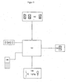
- FIG. 1 shows in the form of a block diagram the typical components, which has an inventive vending machine.
- the focus is on an electronic control and storage unit 101, which is preferably a microprocessor-controlled electronics, which among other things controls the functions of the invention in the vending machine.
- a defined number of spiral drive motors 102 are coupled to the control unit 101, corresponding to the number of goods selection options or goods compartments in the vending machine.
- To the control unit 101 is also a transport drive motor 103 (DC gear motor) coupled to drive the transport device, which moves the removal tray up and down.
- the control unit 101 is provided with a display 104 for customer feedback and any coin / bill acceptor 105 coupled.
- a position control 106 for generating position signals is also coupled to the electronic control and storage unit 101.
- the position control is preferably designed as an infrared fork light barrier.
- FIG. 1 illustrated components are suitable, for example, a vending machine, as in FIG. 2 in a perspective partial sectional view is shown to design according to the invention.
- the in FIG. 2 illustrated vending machine has a front wall 2, which closes the vending machine forward.
- the vending machine has a goods issue area 6 in a lower section.
- a goods storage area is arranged above the goods issue area.
- the goods storage area there are a plurality of superimposed goods compartment groups 12, each having a plurality of juxtaposed goods compartments 10.
- two spirals 18 are arranged in parallel, which are respectively provided for receiving goods, possibly also shock-sensitive goods, between the spiral turns.
- the spirals 18 are opposite to each other and have the spiral drive motors 102 according to FIG.
- the spiral drive motors 102 are in FIG. 2 not shown), which can be driven to feed goods by respective rotation of the spiral 18 with the goods.
- the adjacent goods compartments 10 are separated from each other by partitions 16.
- the goods compartments 10 of the goods compartment group 12 have a common bottom, at the front edge of an edge profile 14 is arranged.
- the front wall 2 of the vending machine is designed as a door, which is posted on a fixed side wall (not shown) of the vending machine.
- the front wall 2 or door has a viewing window 4, which allows a viewer from outside the view of the goods compartment groups 12 in the goods storage area.
- the front wall 2 has a removal opening 8, through which the goods can be removed after the sale of the goods issue area 6 of the vending machine.
- the removal opening 8 is provided with a removal flap 7, which is articulated on the inner surface of the front wall 2 above the removal opening 8 and which is pivotable into the interior of the vending machine.
- the front wall 2 is spaced from the Warrenfach groups 12.
- the area between the front wall 2 and the goods compartment groups 12 forms a transport space in which a transport device 20 is arranged, which is provided for transporting the goods pushed by the spirals 18 over the edge profile 14 of the floor to a removal position in the discharge area 6.
- the transport device 20 contains transmission elements 24, which are designed as endless toothed belts.
- the transmission members 24 pass over upper and lower deflecting members 26 and drive members 28, which are each formed as rotatably mounted rollers.
- the transport device 20 further comprises a drive shaft 30 for driving the drive members 28 and a transport drive motor 103 with a gear 32 for driving the drive shaft 30.
- a removal trough 22 is fastened by means of fastening elements 44.
- the length of the removal trough 22 corresponds to the width of the goods compartment group 12.
- the removal trough 22 is arranged horizontally with its longitudinal axis parallel to the edge profiles 14 and can be moved vertically by means of the transmission elements 24.
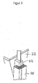
- a transmission member 24 of the transport device 20 is shown in fragmentary detail.
- the transmission member 24 is formed as a toothed belt.
- a fastening element 44 is arranged in each case.
- the fastening element 44 has, for example, a cuboid shape.
- the fastening element 44 consists of two equally parallelepiped jaws. Between opposite surfaces of the jaws, a portion of the toothed belt is guided. The jaws are pressed against each other and attached to the toothed belt.
- the fastener 44 is slidably received in a guide rail 46 which is vertically disposed in the vending machine.
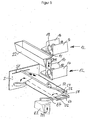
- FIGS. 4 and 5 the goods issue area and a lower portion of the goods storage area of the vending machine are shown.
- the goods issue area 6 is located below the goods storage area with the goods compartment groups 12, which have the goods compartment 10 spaced apart by partitions 16 with the or the spirals 18.
- the goods issue area 6 can be separated from the goods storage area by a blocking flap 50.
- the blocking flap 50 is behind the removal opening 8 (in the FIGS. 4 and 5 not shown).
- the removal flap 50 has two elongate plate-shaped flap sections 52, 56.
- the flap sections 52, 56 are arranged in the longitudinal direction by means of a first hinge 54 to each other pivotally.
- the pivot axis runs horizontally
- the blocking flap 50 is hinged to a fortified in the vending machine horizontal intermediate wall 60 pivotally.
- the pivot axis of the second hinge 55 is parallel to the pivot axis of the first hinge 54.
- a spring 58 is fixed, which is connected to the second flap portion 56 and biases the pivotally attached to the intermediate wall 60 locking flap 50 against the intermediate wall 60.
- the blocking flap 50 and the intermediate wall 60 are bordered by two vertically arranged side walls 3, which are spaced from one another by the length of the first and second flap section 52, 56 and the intermediate wall 60, respectively.
- a guide groove 51 is formed in a portion of the side wall 3.
- the first flap portion 52 has at the opposite end faces in each case a guide pin 66, which is in engagement with the guide groove 51 and forcibly guides the blocking flap 50 during a pivoting movement.
- two actuating lever 64 pivotally mounted.
- a fastener is a third hinge 62 which is struck on the surface with the first hinge 54 of the second hinge 55 opposite.
- the pivot axis of the third hinge 62 is parallel to the pivot axes of the hinges 54, 55.
- the operating levers 64 are formed with a stop and close in a stop position with the second flap portion 56 an angle of not quite 180 a.
- the operating levers 64 below the second flap portion 56 are slightly inclined forwardly from a vertical plane.
- the removal trough 22 is in a removal position in the goods issue area 6 of the vending machine.
- the arranged on the end faces of the removal tray 22 blocks 144 abut the actuating levers 64, and the locking flap 50 is pivoted against the bias of the spring 58 in a closed position.
- the goods storage area of the vending machine located above the blocking flap 50 is closed against the goods issue area 6 in this position of the blocking flap 50.
- a passage through the removal opening 8 (in the FIGS. 4 and 5 not shown) through the goods issue area 6 in the goods storage area is prevented by the locking flap 50 in the closed position.
- the goods storage area is thermally sealed against the goods issue area 6. The goods storage area is thus easy to cool to keep the goods fresh.
- the removal trough 22 is moved from the removal position vertically upward into a desired position.
- a portion of the upper edge of the removal tray 22 is located approximately in front of the profile 14 of the bottom of the goods compartment group 12.
- the locking flap 50 is folded due to the bias of the spring 58 against the intermediate wall 60 and is in a release position, in which Transport space for a movement of the removal tray is released.
- the operating levers 64 are in this. Position folded in an approximately horizontal position. The free ends of the actuating lever 64 project forward to close behind the removal flap 7 (in Figures 3 and 4 not shown), block the removal flap 7 against pivotal movement and thus act as locking means for the removal flap 7, when the removal trough 22 is moved from the removal position.
- the first flap portion 52 which is retracted to the rear due to the action of the spring 58 which holds the locking flap 50 in the release position and biases against the intermediate wall 60.
- the blocks 144 on the end faces of the removal trough 22 press against the actuation levers 64 as the removal trough 22 is lowered further into the goods issue area.
- the removal trough 22 exerts a torque about the axis of the second hinge 55 when lowering onto the blocking flap 50 via the actuating lever 64 and the second flap section 56. The torque causes the second flap portion 56 to pivot against the bias of the spring 58 to a vertical position.
- first flap portion 52 is thereby moved to from in a horizontal position on the removal tray 22.
- the blocking flap 50 is in the closed position.
- the removal trough 22 can be moved from the removal position further down to a maintenance position; in FIG. 5 a portion of the removal tray 22 is shown in dashed lines in the maintenance position.
- the removal trough 22 is located so low in the maintenance position, that the blocks 144 are below the operating lever 64 and they do not hit the blocks 144.
- the barrier flap 50 is pivoted in accordance with the bias of the spring 58 or withdrawn to the rear wall of the vending machine.
- the removal trough 22 is moved back to the removal position above the maintenance position.
- the pivotally mounted on the second flap portion 56 actuating lever 64 are thereby pivoted by the upwardly driven removal tray 22 upwards.
- the removal trough 22 has moved so far into the height that the removal trough 22 releases the actuation lever 64, the actuation levers 64 fall back downwards due to their own weight.
- FIG. 6 shows the flowchart or the logic diagram of a typical sales process with the possible flow options related to the movement of the removal trough 22.
- the required logic is preferably as software in the electronic control and storage unit 101 of FIG. 1 realized.
- the transport drive motor 103 receives a signal to move the removal trough, the removal trough from a neutral position, which is typically in the vicinity or in the dispensing area 6 of the vending machine, toward a target position for taking over To move goods.
- the position control means 106 provide a position pulse.
- a counter or other timer
- step 204 it is checked whether a time limit has been exceeded. As long as no time limit has been exceeded, the removal trough is moved further in the direction of the desired position in step 201.
- step 205 If a position pulse then arrives at the control and storage unit 101 in step 202, it is checked in step 205 whether the target position has already been reached. If the target position has not yet been reached, a branch is made back to step 201, in which the transport device 20 is further caused to move the removal trough in the direction of the desired position. In step 202 it is again checked whether a position pulse arrives and the logic branches back to step 201 according to the criteria already described.
- step 205 if it is detected in step 205 that the target position has been reached, a product is ejected in step 206.
- the corresponding spiral drive motor 102 is put into operation until the goods are issued and this is then in the removal trough 22. Then, in step 207, the removal trough 22 is moved to the removal position. If the removal position is reached in step 208, the sales process ends, with any excess money being returned, etc.
- the operation will be described when the sampling tray 22 is blocked in a position so that it can not exceed a certain position which does not yet correspond to the target position. This is done in practice, for example, by poor filling of the vending machine, which can lead to a blockage of the removal tray 22 in the upward movement by protruding from the goods compartments 10 goods. But there are also other reasons for a blockage conceivable, such. Foreign bodies or dysfunctions of the transport device.
- step 201 the removal trough 22 as previously moved in the direction of the desired position.
- the control unit 101 checks the position pulses of the position control means 106 in step 202. During this check, a counter arranged in the electronic memory and control unit 101, which acts as a timekeeper, is incremented in step 203. Based on this timer, the control unit 101 determines in step 204 whether a predetermined time limit has been exceeded is, without in step 202, another position pulse has occurred. If the time limit is exceeded, the logic branches to step 212.
- step 212 the electronic storage and control unit 101 stores the last determined position of the removal trough 22 or alternatively the not yet reached position as a blockage position.
- step 213 a count for the number of start attempts is incremented by one.
- step 214 a blocking flag is set indicating that there is a blockage.
- step 207 the removal trough 22 is moved down again in the direction of the removal position. Instead of the removal position, another neutral position comes into question.
- step 208 it is checked if this position is reached. If not, the process branches back to step 207 and the removal trough 22 is moved further down. If the removal position (or other neutral position) is reached, it is checked in step 209 whether there was a blockage. This is done by checking the blocking flag in step 209. If the blocking flag is set, a branch is made to step 211.
- step 211 a check of the number of start attempts takes place. As long as a predefined number of attempts to start - for example, three attempts - has not been reached, a branch is made to step 201.
- step 201 the removal tray is moved up again from the picking position or the neutral position. As described above, an attempt is again made to reach the desired position with the removal trough 22. If the time limit is exceeded once more in step 204 before another position pulse occurs, the blockage position is again stored in step 212 and the number of attempts to start again in step 213 is increased by 1 and the blocking flag is set in step 214.
- the withdrawal tub 22 is returned to the removal position or the neutral position in steps 207 and 208 and it is checked in step 209 whether there was a blockage. If this is the case, the number of startup attempts is checked again. Finally agrees with the number of start attempts the predefined maximum number of attempts to start, the sales process is terminated in step 210. The customer is then informed on the display 104 that he can either change the selection for the goods or get his money back. Subsequently, the electronic control and storage unit 101 of the invention can take the blockage position in the control process and apply in future sales transactions, a special treatment routine, which will be described below with reference to Fig. 7 is described.
- step 301 the electronic control and storage unit 101 checks in step 301 whether a blockage position is stored. If this is not the case, a normal sales routine is performed in step 302 and the sales process is ended in step 307. However, if it is determined in step 301 that a blockage position is stored, it is determined in the following step 303, whether the goods requested by the customer's goods selection in a goods compartment 10, which is unreachable due to the stored blockage position with the removal tray 22 , If this is not the case, a normal sales routine is performed in step 302.
- step 304 the control unit 101 decides whether a sales process can be carried out even if the removal trough 22 is still away from the target position. This is decided, for example, according to whether a product can fall from a higher area of the vending machine into the removal tray 22 without the goods being damaged. If the output of the product is possible, although the removal trough 22 does not reach the actual target position for the gentle dispensing of the product, the choice is released in step 304.
- step 305 the target position for future sales transactions is replaced by a value corresponding to the blockage position (eg blockage position -1 depending on the type of counter).
- step 302 a normal sales routine is executed, which is completed in step 307.
- the vending machine signals in step 306, the sale stop and asks the customer to choose another product or cancel the sale process to get the money back.
- step 307 the sales process is then completed.
Landscapes
- Physics & Mathematics (AREA)
- General Physics & Mathematics (AREA)
- Business, Economics & Management (AREA)
- Accounting & Taxation (AREA)
- Control Of Vending Devices And Auxiliary Devices For Vending Devices (AREA)
- Vending Machines For Individual Products (AREA)
Claims (16)
- Distributeur automatique comportant plusieurs compartiments de distribution superposés (10) comportant des moyens de délivrance (18, 102) pour chaque compartiment de distribution (10), qui délivre respectivement lors de l'activation un produit depuis le compartiment de distribution en (10), comportant au moins un dispositif de transport (20), qui peut être entraîné par des moyens d'entraînement (26, 28, 30, 32, 103), et qui transporte les produits délivrés par les moyens de délivrance (18) grâce à un bac de réception (22) vers une position de réception, et comportant une unité électronique de commande et de mémoire (101) pour commander le dispositif de transport (20), afin d'amener le bac de réception (22) dans une position de consigne devant le compartiment de distribution activé respectif (10) pour recevoir un produit, et ensuite dans la zone de délivrance du produit (6) dans la position de réception pour recevoir le produit, caractérisé en ce que l'unité électronique de commande et de mémoire (101) est réalisée, pour déterminer et mémoriser une position de blocage, à partir de laquelle le bac de réception (22) ne peut pas être amené plus loin dans la direction de la position de consigne avant d'avoir atteint la position de consigne.
- Distributeur automatique selon la revendication 1, caractérisé par des moyens de contrôle de position (106) pour générer un signal de position correspondant à une position réelle du bac de réception (22).
- Distributeur automatique selon la revendication 1 ou 2, caractérisé en ce que l'unité électronique de commande et de mémoire (101) est réalisée, afin de détecter le dépassement d'une limite de temps, au cas où le bac de réception (22) n'atteint pas une position réelle prédéfinie pendant l'approche de la position de consigne.
- Distributeur automatique selon la revendication 3, caractérisé en ce que l'unité électronique de commande et de mémoire (101) est réalisée, afin de mémoriser une position de blocage, lorsque le dépassement de la limite de temps a été détecté.
- Distributeur automatique selon la revendication 3 ou 4, caractérisé en ce que l'unité de commande et de mémoire (101) est réalisée, afin d'effectuer au moins une seconde tentative d'approche avec le bac de réception (22), pour atteindre une position de consigne, au cas où un dépassement de la limite de temps a été détecté pendant la tentative d'approche respective précédente.
- Distributeur automatique selon la revendication 5, caractérisé en ce que l'unité de commande et de mémoire (101) est réalisée, afin de détecter le nombre de tentatives d'approche, lors desquelles un dépassement de la limite de temps a été détecté.
- Distributeur automatique selon la revendication 6, caractérisé en ce que l'unité de commande et de mémoire (101) est réalisée, afin de terminer le processus de vente après avoir atteint un chiffre prédéfini de plus de deux tentatives d'approche dépassant la limite de temps.
- Distributeur automatique selon l'une des revendications précédentes, caractérisé en ce que l'unité de commande et de mémoire (101) est réalisée, afin de tenir compte de la position de blocage détectée et mémorisée lors de la première tentative de vente pendant une seconde tentative de vente ultérieure, pendant laquelle les produits du compartiment de produits activé (10) ne sont plus proposés à la vente dans une position de consigne du bac de réception (22) correspondant ne pouvant plus être atteint.
- Distributeur automatique selon l'une des revendications 1 à 7, caractérisé en ce que l'unité électronique de commande et de mémoire (101) est réalisée, afin de tenir compte de la position de blocage détectée et mémorisée lors d'une première tentative de vente pendant une seconde tentative de vente ultérieure, dans laquelle les produits du compartiment de produits activé (10) dans une position de consigne du bac de réception correspondant ne pouvant pas être atteint sont mis en vente uniquement, dans le cas où le produit a été délivré par le compartiment de produits activé (10) dans le bac de réception (22) malgré le blocage.
- Distributeur automatique selon l'une des revendications précédentes, caractérisé en ce que plusieurs compartiments de produits respectifs (10) sont disposés les uns à côté des autres de sorte que les compartiments de produits (10) forment un groupe horizontal de compartiments de produits (12), plusieurs groupes de compartiments de produits (12) sont disposés écartés les uns au-dessus des autres et le bac de réception (22) s'étend sur toute la largeur horizontale d'un groupe de compartiments de produits (12).
- Procédé pour actionner un distributeur automatique comportant plusieurs compartiments de produits superposés (10) comportant des moyens de délivrance (18) pour chaque compartiment de produits (10), qui délivre respectivement lors de l'activation, un produit à partir du compartiment de produits (10), comportant au moins un dispositif de transport (20), qui transporte vers une position de réception les produits délivrés par les moyens de délivrance (18) grâce à un bac de réception (22), et comportant une unité électronique de commande et de mémoire (101) pour commander le dispositif de transport (20), afin d'amener le bac de réception (22) dans une position de consigne devant le compartiment de produits respectif activé (10) pour réceptionner un produit, et ensuite dans la zone de délivrance du produit (6) dans la position de réception pour recevoir le produit, caractérisé par l'étape consistant à :- détecter et mémoriser une position de blocage, à partir de laquelle le bac de réception (22) ne peut plus être déplacé dans la direction de la position de consigne avant d'avoir atteint la position de consigne.
- Procédé selon la revendication 11, caractérisé par l'étape consistant à- générer un signal de position correspondant à une position réelle du bac de réception (22).
- Procédé selon la revendication 11 ou 12, caractérisé par l'étape consistant à- détecter un dépassement d'une limite de temps, dans le cas où le bac de réception (22) n'atteint pas une position réelle prédéfinie pendant l'approche de la position de consigne.
- Procédé selon la revendication 13, caractérisé par les étapes consistant à- effectuer une autre tentative d'approche de la position de consigne avec le bac de réception (22), lorsqu'un dépassement de la limite de temps a été détecté pendant la tentative d'approche respective précédente,- détecter le nombre de tentatives d'approche, lors desquelles un dépassement de la limite de temps a été détecté, et- mettre fin au processus de vente après avoir atteint un nombre prédéterminé de plus de deux tentatives d'approche dépassant la limite de temps.
- Procédé selon l'une des revendications 11 à 14, caractérisé par les étapes consistant à- mémoriser la position de blocage détectée lors d'une première tentative de vente pour une seconde tentative de vente ultérieure, et- annoncer que les produits du compartiment de produits activé (10) ne peuvent plus être vendus dans une position de consigne du bac de réception (22) correspondant ne pouvant pas être atteint prédéfini en fonction de la position de blocage mémorisée.
- Procédé selon l'une des revendications 11 à 14, caractérisé par les étapes consistant à- mémoriser la position de blocage détectée lors de la première tentative de vente pour au moins une seconde tentative de vente ultérieure, et- délivrer les produits à partir d'un compartiment de produits activé (10) dans une position de consigne du bac de réception (22) correspondant ne pouvant pas être atteint en fonction de la position de blocage mémorisée, au cas où le produit peut être délivré par le compartiment de produits activé (10) malgré le blocage du bac de réception (22).
Applications Claiming Priority (2)
| Application Number | Priority Date | Filing Date | Title |
|---|---|---|---|
| DE102005006473A DE102005006473A1 (de) | 2005-02-12 | 2005-02-12 | Ablaufsteuerung für Warenautomat |
| PCT/EP2005/011268 WO2006084487A2 (fr) | 2005-02-12 | 2005-10-20 | Commande sequentielle pour un distributeur automatique |
Publications (2)
| Publication Number | Publication Date |
|---|---|
| EP1851733A2 EP1851733A2 (fr) | 2007-11-07 |
| EP1851733B1 true EP1851733B1 (fr) | 2008-05-21 |
Family
ID=35985247
Family Applications (1)
| Application Number | Title | Priority Date | Filing Date |
|---|---|---|---|
| EP05798495A Expired - Lifetime EP1851733B1 (fr) | 2005-02-12 | 2005-10-20 | Commande sequentielle pour un distributeur automatique |
Country Status (4)
| Country | Link |
|---|---|
| US (1) | US20070257054A1 (fr) |
| EP (1) | EP1851733B1 (fr) |
| DE (2) | DE102005006473A1 (fr) |
| WO (1) | WO2006084487A2 (fr) |
Families Citing this family (4)
| Publication number | Priority date | Publication date | Assignee | Title |
|---|---|---|---|---|
| ITTO20070894A1 (it) * | 2007-12-11 | 2009-06-12 | N&W Global Vending Spa | Metodo e dispositivo per il trasferimento di prodotti all'interno di un distributore automatico |
| ITMI20120295A1 (it) * | 2012-02-28 | 2013-08-29 | Damian S R L | Macchina distributrice automatica di prodotti |
| DE102014106360B4 (de) * | 2014-05-07 | 2022-01-20 | R. Weiss Verpackungstechnik Gmbh & Co. Kg | Ausgabeeinheit für Backprodukte |
| ITUA20163104A1 (it) * | 2016-05-03 | 2017-11-03 | Rheavendors Services Spa | Macchina distributrice automatica di prodotti. |
Family Cites Families (8)
| Publication number | Priority date | Publication date | Assignee | Title |
|---|---|---|---|---|
| US4896024A (en) * | 1987-10-19 | 1990-01-23 | Diebold, Incorporated | Apparatus for dispensing and accepting return of reusable articles |
| US5499707A (en) * | 1995-01-31 | 1996-03-19 | Compu-Shop, Inc. | Automated merchandising kiosk |
| US6131399A (en) * | 1997-12-04 | 2000-10-17 | Hall; Donald M. | Refrigerated vending machine |
| US6199720B1 (en) * | 1998-03-20 | 2001-03-13 | The Coca-Cola Company | Vending machine |
| DE19946609B4 (de) * | 1999-09-29 | 2005-08-11 | Deutsche Wurlitzer Gmbh | Warenautomat mit mehreren übereinander angeordneten Warenfächern |
| US6755322B1 (en) * | 2000-02-22 | 2004-06-29 | Hettie J. Herzog | Automated shopping system and apparatus |
| US7123989B2 (en) * | 2003-07-01 | 2006-10-17 | Asteres, Inc. | System and method for providing a random access and random load dispensing unit |
| US7233241B2 (en) * | 2004-11-19 | 2007-06-19 | Goliath Solutions, Llc | Low stock alert system |
-
2005
- 2005-02-12 DE DE102005006473A patent/DE102005006473A1/de not_active Withdrawn
- 2005-10-20 US US11/662,807 patent/US20070257054A1/en not_active Abandoned
- 2005-10-20 WO PCT/EP2005/011268 patent/WO2006084487A2/fr not_active Ceased
- 2005-10-20 EP EP05798495A patent/EP1851733B1/fr not_active Expired - Lifetime
- 2005-10-20 DE DE502005004234T patent/DE502005004234D1/de not_active Expired - Lifetime
Also Published As
| Publication number | Publication date |
|---|---|
| DE502005004234D1 (de) | 2008-07-03 |
| WO2006084487A3 (fr) | 2006-12-07 |
| DE102005006473A1 (de) | 2006-08-17 |
| EP1851733A2 (fr) | 2007-11-07 |
| WO2006084487A2 (fr) | 2006-08-17 |
| US20070257054A1 (en) | 2007-11-08 |
Similar Documents
| Publication | Publication Date | Title |
|---|---|---|
| DE69826305T2 (de) | Vorrichtung und verfahren zum verkaufen von erzeugnissen | |
| EP1119830B1 (fr) | Distributeur automatique de cigarettes | |
| DE3789709T2 (de) | Ausgeber für flache Gegenstände. | |
| DE3516384C2 (fr) | ||
| DE69720036T2 (de) | Verkaufsautomat | |
| DE1926634A1 (de) | Warenautomat | |
| EP1947619B1 (fr) | Rayon de marchandises, dispositif de prélèvement, automate de vente et procédé | |
| DE3630191A1 (de) | Vorrichtung zur ausgabe von muenzenrollen | |
| DE19946609B4 (de) | Warenautomat mit mehreren übereinander angeordneten Warenfächern | |
| EP1423314A1 (fr) | Magasin a rayonnage comportant des tiroirs montes dans les compartiments de rayonnage | |
| DE102013012763B4 (de) | Warenautomat | |
| EP1851733A2 (fr) | Commande sequentielle pour un distributeur automatique | |
| WO2017021456A1 (fr) | Système de distribution d'articles | |
| DE10061462A1 (de) | Leerflaschen-Rücknahmeautomat | |
| DE102014008885A1 (de) | Verkaufsautomat | |
| DE69607080T2 (de) | Verkaufsautomat, insbesondere zum Verkauf von Verpackungen von Speiseeis oder tiefgefrorenen Lebensmitteln | |
| DE4444791A1 (de) | Verkaufsautomat | |
| DE3140084A1 (de) | Zeitungsverkaufsautomat | |
| DE19710624B4 (de) | Vorrichtung zur Ausgabe von Druckerzeugnissen, insbesondere Zeitungen und Zeitschriften | |
| EP1347423A2 (fr) | Dispositif de distribution | |
| EP4488972A1 (fr) | Station de vente pour la distribution automatique de marchandises à un acheteur | |
| EP4492350A1 (fr) | Distributeur automatique pour stocker et distribuer un produit, station de distribution automatique pour distribuer automatiquement des produits à un acheteur, et procédé de distribution d'un produit à partir d'un distributeur automatique | |
| DE102007058978A1 (de) | Getränkeautomaten-Container-System | |
| EP0795495A2 (fr) | Dispositif de chargement | |
| DE3941893A1 (de) | Ausgabevorrichtung |
Legal Events
| Date | Code | Title | Description |
|---|---|---|---|
| PUAI | Public reference made under article 153(3) epc to a published international application that has entered the european phase |
Free format text: ORIGINAL CODE: 0009012 |
|
| 17P | Request for examination filed |
Effective date: 20070912 |
|
| AK | Designated contracting states |
Kind code of ref document: A2 Designated state(s): CH DE FR LI NL |
|
| GRAP | Despatch of communication of intention to grant a patent |
Free format text: ORIGINAL CODE: EPIDOSNIGR1 |
|
| DAX | Request for extension of the european patent (deleted) | ||
| RBV | Designated contracting states (corrected) |
Designated state(s): CH DE FR LI NL |
|
| GRAS | Grant fee paid |
Free format text: ORIGINAL CODE: EPIDOSNIGR3 |
|
| GRAA | (expected) grant |
Free format text: ORIGINAL CODE: 0009210 |
|
| AK | Designated contracting states |
Kind code of ref document: B1 Designated state(s): CH DE FR LI NL |
|
| REG | Reference to a national code |
Ref country code: CH Ref legal event code: EP Ref country code: CH Ref legal event code: PFA Owner name: DEUTSCHE WURLITZER GMBH Free format text: DEUTSCHE WURLITZER GMBH#NIEDERDORF 5#32351 STEMWEDE-LEVERN (DE) -TRANSFER TO- DEUTSCHE WURLITZER GMBH#WURLITZER STRASSE 6#32609 HUELLHORST (DE) Ref country code: CH Ref legal event code: NV Representative=s name: E. BLUM UND CO. AG PATENT- UND MARKENANWAELTE VSP |
|
| REF | Corresponds to: |
Ref document number: 502005004234 Country of ref document: DE Date of ref document: 20080703 Kind code of ref document: P |
|
| PLBE | No opposition filed within time limit |
Free format text: ORIGINAL CODE: 0009261 |
|
| STAA | Information on the status of an ep patent application or granted ep patent |
Free format text: STATUS: NO OPPOSITION FILED WITHIN TIME LIMIT |
|
| 26N | No opposition filed |
Effective date: 20090224 |
|
| REG | Reference to a national code |
Ref country code: CH Ref legal event code: PUE Owner name: GIBSON GUITAR CORP. Free format text: DEUTSCHE WURLITZER GMBH#WURLITZER STRASSE 6#32609 HUELLHORST (DE) -TRANSFER TO- GIBSON GUITAR CORP.#309 PLUS PARK BOULEVARD#NASHVILLE, TN 37217 (US) |
|
| REG | Reference to a national code |
Ref country code: NL Ref legal event code: SD Effective date: 20121017 |
|
| REG | Reference to a national code |
Ref country code: FR Ref legal event code: TP Owner name: GIBSON GUITAR CORP., US Effective date: 20121026 |
|
| REG | Reference to a national code |
Ref country code: DE Ref legal event code: R082 Ref document number: 502005004234 Country of ref document: DE Representative=s name: EISENFUEHR SPEISER PATENTANWAELTE RECHTSANWAEL, DE Effective date: 20130307 Ref country code: DE Ref legal event code: R082 Ref document number: 502005004234 Country of ref document: DE Representative=s name: VON KREISLER SELTING WERNER, DE Effective date: 20130307 Ref country code: DE Ref legal event code: R081 Ref document number: 502005004234 Country of ref document: DE Owner name: GIBSON GUITAR CORP., US Free format text: FORMER OWNER: DEUTSCHE WURLITZER GMBH, 32351 STEMWEDE, DE Effective date: 20130307 Ref country code: DE Ref legal event code: R081 Ref document number: 502005004234 Country of ref document: DE Owner name: DEUTSCHE WURLITZER GMBH, DE Free format text: FORMER OWNER: DEUTSCHE WURLITZER GMBH, 32351 STEMWEDE, DE Effective date: 20130307 |
|
| REG | Reference to a national code |
Ref country code: CH Ref legal event code: PUE Owner name: DEUTSCHE WURLITZER GMBH, DE Free format text: FORMER OWNER: GIBSON GUITAR CORP., US |
|
| REG | Reference to a national code |
Ref country code: DE Ref legal event code: R082 Ref document number: 502005004234 Country of ref document: DE Representative=s name: EISENFUEHR SPEISER PATENTANWAELTE RECHTSANWAEL, DE Effective date: 20131024 Ref country code: DE Ref legal event code: R081 Ref document number: 502005004234 Country of ref document: DE Owner name: DEUTSCHE WURLITZER GMBH, DE Free format text: FORMER OWNER: GIBSON GUITAR CORP., NASHVILLE, US Effective date: 20131024 Ref country code: DE Ref legal event code: R081 Ref document number: 502005004234 Country of ref document: DE Owner name: DEUTSCHE WURLITZER GMBH, DE Free format text: FORMER OWNER: GIBSON GUITAR CORP., NASHVILLE, TENN., US Effective date: 20131024 |
|
| REG | Reference to a national code |
Ref country code: FR Ref legal event code: TP Owner name: DEUTSCHE WURLITZER GMBH, DE Effective date: 20131206 |
|
| REG | Reference to a national code |
Ref country code: NL Ref legal event code: SD Effective date: 20140312 |
|
| REG | Reference to a national code |
Ref country code: FR Ref legal event code: PLFP Year of fee payment: 11 |
|
| PGFP | Annual fee paid to national office [announced via postgrant information from national office to epo] |
Ref country code: DE Payment date: 20151103 Year of fee payment: 11 Ref country code: CH Payment date: 20151026 Year of fee payment: 11 |
|
| PGFP | Annual fee paid to national office [announced via postgrant information from national office to epo] |
Ref country code: NL Payment date: 20151026 Year of fee payment: 11 Ref country code: FR Payment date: 20151026 Year of fee payment: 11 |
|
| REG | Reference to a national code |
Ref country code: DE Ref legal event code: R082 Ref document number: 502005004234 Country of ref document: DE |
|
| REG | Reference to a national code |
Ref country code: DE Ref legal event code: R119 Ref document number: 502005004234 Country of ref document: DE |
|
| REG | Reference to a national code |
Ref country code: CH Ref legal event code: PL |
|
| REG | Reference to a national code |
Ref country code: NL Ref legal event code: MM Effective date: 20161101 |
|
| REG | Reference to a national code |
Ref country code: FR Ref legal event code: ST Effective date: 20170630 |
|
| PG25 | Lapsed in a contracting state [announced via postgrant information from national office to epo] |
Ref country code: FR Free format text: LAPSE BECAUSE OF NON-PAYMENT OF DUE FEES Effective date: 20161102 Ref country code: CH Free format text: LAPSE BECAUSE OF NON-PAYMENT OF DUE FEES Effective date: 20161031 Ref country code: LI Free format text: LAPSE BECAUSE OF NON-PAYMENT OF DUE FEES Effective date: 20161031 Ref country code: DE Free format text: LAPSE BECAUSE OF NON-PAYMENT OF DUE FEES Effective date: 20170503 |
|
| PG25 | Lapsed in a contracting state [announced via postgrant information from national office to epo] |
Ref country code: NL Free format text: LAPSE BECAUSE OF NON-PAYMENT OF DUE FEES Effective date: 20161101 |