EP1852038A1 - Drehgelenk für Bettseitenschutz - Google Patents
Drehgelenk für Bettseitenschutz Download PDFInfo
- Publication number
- EP1852038A1 EP1852038A1 EP06113517A EP06113517A EP1852038A1 EP 1852038 A1 EP1852038 A1 EP 1852038A1 EP 06113517 A EP06113517 A EP 06113517A EP 06113517 A EP06113517 A EP 06113517A EP 1852038 A1 EP1852038 A1 EP 1852038A1
- Authority
- EP
- European Patent Office
- Prior art keywords
- gear
- shells
- button
- fixing
- rotating shaft
- Prior art date
- Legal status (The legal status is an assumption and is not a legal conclusion. Google has not performed a legal analysis and makes no representation as to the accuracy of the status listed.)
- Withdrawn
Links
- 230000008878 coupling Effects 0.000 claims description 8
- 238000010168 coupling process Methods 0.000 claims description 8
- 238000005859 coupling reaction Methods 0.000 claims description 8
- 238000003780 insertion Methods 0.000 description 6
- 230000037431 insertion Effects 0.000 description 6
- 230000008859 change Effects 0.000 description 1
- 238000000034 method Methods 0.000 description 1
- 238000012986 modification Methods 0.000 description 1
- 230000004048 modification Effects 0.000 description 1
- 230000008569 process Effects 0.000 description 1
Images


Classifications
-
- F—MECHANICAL ENGINEERING; LIGHTING; HEATING; WEAPONS; BLASTING
- F16—ENGINEERING ELEMENTS AND UNITS; GENERAL MEASURES FOR PRODUCING AND MAINTAINING EFFECTIVE FUNCTIONING OF MACHINES OR INSTALLATIONS; THERMAL INSULATION IN GENERAL
- F16C—SHAFTS; FLEXIBLE SHAFTS; ELEMENTS OR CRANKSHAFT MECHANISMS; ROTARY BODIES OTHER THAN GEARING ELEMENTS; BEARINGS
- F16C11/00—Pivots; Pivotal connections
- F16C11/04—Pivotal connections
- F16C11/10—Arrangements for locking
-
- A—HUMAN NECESSITIES
- A47—FURNITURE; DOMESTIC ARTICLES OR APPLIANCES; COFFEE MILLS; SPICE MILLS; SUCTION CLEANERS IN GENERAL
- A47C—CHAIRS; SOFAS; BEDS
- A47C21/00—Attachments for beds, e.g. sheet holders or bed-cover holders; Ventilating, cooling or heating means in connection with bedsteads or mattresses
- A47C21/08—Devices for prevention against falling-out, e.g. detachable side walls
-
- A—HUMAN NECESSITIES
- A47—FURNITURE; DOMESTIC ARTICLES OR APPLIANCES; COFFEE MILLS; SPICE MILLS; SUCTION CLEANERS IN GENERAL
- A47D—FURNITURE SPECIALLY ADAPTED FOR CHILDREN
- A47D15/00—Accessories for children's furniture, e.g. safety belts or baby-bottle holders
- A47D15/005—Restraining devices, e.g. safety belts, contoured cushions or side bumpers
- A47D15/008—Restraining devices, e.g. safety belts, contoured cushions or side bumpers in beds, play-pens or cradles
-
- A—HUMAN NECESSITIES
- A61—MEDICAL OR VETERINARY SCIENCE; HYGIENE
- A61G—TRANSPORT, PERSONAL CONVEYANCES, OR ACCOMMODATION SPECIALLY ADAPTED FOR PATIENTS OR DISABLED PERSONS; OPERATING TABLES OR CHAIRS; CHAIRS FOR DENTISTRY; FUNERAL DEVICES
- A61G7/00—Beds specially adapted for nursing; Devices for lifting patients or disabled persons
- A61G7/05—Parts, details or accessories of beds
- A61G7/0507—Side-rails
- A61G7/0518—Side-rails quickly removable
Definitions
- the present invention relates to an easily operable rotating shaft for a handrail of a bed, which is suitable for a baby bed, a sickbed or the like.
- the protection handrails are usually mounted beside baby beds and sickbeds to protect babies, children, and patients from the risk of fall.
- Two turning devices are mounted on both ends of the handrails, respectively, so as to stand up or fold up the handrails by releasing these two turning devices simultaneously.
- the turning device comprises a slidable insertion device, a bracket, an elastic device, and a resisting device, wherein the elastic device is connected to one end of the resisting device and the slidable insertion device is connected to the other end of the resisting device.
- a U-shaped trench is formed on the bracket for the insertion of the slidable insertion device, whereby the slideable insertion device is slidably mounted in the bracket by using the resisting device and the elastic device, which are connected to the inside of the slideable insertion device, so as to overturn the handrail.
- the present inventor makes diligent studies in providing the consumers with a rotating shaft that can be released easily by a single user.
- a rotating shaft for a handrail of a bed comprises: two shells; a spring; a gear; and a button, wherein two fixing pillars are protrudent from one side of the gear, two matched chambers are formed on the shells, respectively, for being coupled with each other.
- Two fixing trenches are formed in the chamber of one of the shells for holding the fixing pillars of the gear.
- a button trench is formed on the backside of the fixing trenches for holding a button.
- the shells are coupled with each other after the spring and the gear are located in the chambers of the shells, whereby the fixing pillars of the gear are separable from the fixing trenches of the shell by pressing the button such that the other shell is angularly adjustable by rotation.
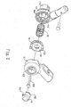
- a rotating shaft 1 of the present invention comprises two shells 10, 11, a spring 12, a gear 13, and a button 14, wherein two matched chambers, which are formed on one side of these two shells 10, 11, respectively, can be jointed together.
- the other side of the shells 10, 11 is designed to be a coupling part for being coupled with another tube.
- a coupling pillar 101 is protrudent from the center of the chamber of the shell 10, wherein a trench is formed on the backside of the coupling pillar 101.
- two arc-shaped openings 103 and 104 are formed oppositely on the both sides of the coupling pillar 101.
- two fixing trenches 102 are formed on the shell 10 adjacent to the openings 103 and 104, respectively.
- a larger-diameter protrudent pillar III is located on the center of the chamber of the shell 11 for holding the coupling pillar 101 of the shell 10.
- An inner-toothed trench 112, which is engageable with the gear 13, is formed on the periphery of the chamber of the shell 11.
- a horizontal jointer 113 is located on the backside of the chamber of the shell 11.
- the gear 13 has a tooth-shaped periphery and a central hole 131 on the center thereof, wherein the central hole 131 matches with the protrudent pillar 11 of the shell 11 in diameter dimension.
- Two fixing pillars 132 are mounted oppositely on the same plane of the gear 131.
- the button 14 is a hollow cylinder having a top surface.
- Two trenches 141 are formed oppositely on the body of cylinder.
- two protrudent flanges 142 are mounted oppositely on the outer surface of the bottom of the remained body of the cylinder.
- the protrudent pillar 111 of the chamber of the shell 11 is inserted into the spring 12.
- the fixing pillars 132 of the gear 13 are located upward such that the central hole 131 of the gear 13 is posited to aim at the protrudent pillar 111.
- the tooth-shaped periphery of the gear 13 is engaged with the trench 112 of the shell 11.
- the chamber of the shell 10 is coupled with the chamber of the shell 11 so as to insert the coupling pillar 101 of the shell 10 into the protrudent pillar 111 of the shell 11.
- a rivet 105 is inserted into the coupling pillar 101 and riveted so as to integrate the shell 11, the spring 12, the gear 13, and the shell 10 into a unity.
- the body of the cylinder of the button 14 is inserted into the openings 103 and 104 so as to hook the openings 103 and 104 by using the protrudent flanges 142, thereby positing the button 14 in the trenches of the shell 10 securely to prevent them from detachment.
- the assembling process of the rotating shaft 1 is completed.
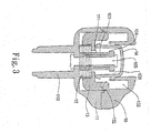
- the spring 12 is located to lean against the bottom surface of the gear 13.
- the fixing pillars 132 of the gear 13 are located in the fixing trenches 102.
- the tube on the other end of the shell 10 is perpendicular to the tube on the other end of the shell 11.
- the body of the cylinder is also pressed down to lean against the top surface of the gear 13 so as to separate the fixing pillars 132 of the gear 3 from the fixing trenches 102 (shown in FIG. 3).
- the shells 10, 11 are rotatable so as to change the included angle between the tubes of the shells 10, 11.
- a flat tube 4 is coupled with the tubes of the shells 10 simultaneously; wherein the tubes of the shells 11 are coupled with two tubes 2, respectively.
- the tubes 2 are coupled with one end of two turning devices 3, respectively.
- another two tubes 2 are further coupled with the other end of the turning devices 3, respectively.
- the horizontal jointers 113 of the shells 11 are further coupled with further two tubes 2, respectively.
- the horizontal tubes 2 are coupled with each other to form a longer handrail.
- the handrail is located above the lateral of a sickbed. If there is a need to put down the handrail, the button 14 on one side of the handrail is pressed down first and the vertical tubes 2 are shifted slightly to enable the shell 11 to drive the gear 13, thereby separating the fixing pillars 132 from the fixing trenches 102. At this moment, the user can go to the other side of the sickbed to press the button 14 on the other side of the handrail. Thereafter, the vertical tubes 2 are rotated downward so as to rotate and shift the handrail to the lower portion of the sickbed.
- the present invention indeed achieves the expected objects of providing the easily operable rotating shaft. Accordingly, the present invention satisfies the requirement for patentability and is therefore submitted for a patent.
Landscapes
- Health & Medical Sciences (AREA)
- General Health & Medical Sciences (AREA)
- Nursing (AREA)
- Life Sciences & Earth Sciences (AREA)
- Animal Behavior & Ethology (AREA)
- Public Health (AREA)
- Veterinary Medicine (AREA)
- Engineering & Computer Science (AREA)
- General Engineering & Computer Science (AREA)
- Mechanical Engineering (AREA)
- Pediatric Medicine (AREA)
- Invalid Beds And Related Equipment (AREA)
Priority Applications (1)
| Application Number | Priority Date | Filing Date | Title |
|---|---|---|---|
| EP06113517A EP1852038A1 (de) | 2006-05-04 | 2006-05-04 | Drehgelenk für Bettseitenschutz |
Applications Claiming Priority (1)
| Application Number | Priority Date | Filing Date | Title |
|---|---|---|---|
| EP06113517A EP1852038A1 (de) | 2006-05-04 | 2006-05-04 | Drehgelenk für Bettseitenschutz |
Publications (1)
| Publication Number | Publication Date |
|---|---|
| EP1852038A1 true EP1852038A1 (de) | 2007-11-07 |
Family
ID=37055133
Family Applications (1)
| Application Number | Title | Priority Date | Filing Date |
|---|---|---|---|
| EP06113517A Withdrawn EP1852038A1 (de) | 2006-05-04 | 2006-05-04 | Drehgelenk für Bettseitenschutz |
Country Status (1)
| Country | Link |
|---|---|
| EP (1) | EP1852038A1 (de) |
Cited By (5)
| Publication number | Priority date | Publication date | Assignee | Title |
|---|---|---|---|---|
| EP2430949A1 (de) * | 2010-09-16 | 2012-03-21 | Brevi S.R.L. | Sicherheitsabgrenzung für Betten, insbesondere des abklappbaren Typs |
| CN101849750B (zh) * | 2009-04-02 | 2012-07-04 | 明门香港股份有限公司 | 用于连接一顶蓬的顶蓬卡座组 |
| CN103909964A (zh) * | 2014-04-28 | 2014-07-09 | 浙江德清久胜车业有限公司 | 旋转亲子车的推把固定座 |
| CN106724400A (zh) * | 2017-01-22 | 2017-05-31 | 夏畏 | 一种床护栏 |
| CN107117201A (zh) * | 2017-06-23 | 2017-09-01 | 黄兵修 | 一种多用途扶手及推车 |
Citations (6)
| Publication number | Priority date | Publication date | Assignee | Title |
|---|---|---|---|---|
| DE29706026U1 (de) * | 1997-03-17 | 1997-05-28 | Lan, Red, Chia-Li, Tainan | Schwenkgelenk für einen Kinderwagenrahmen |
| US5671790A (en) | 1996-01-24 | 1997-09-30 | V. Kann Rasmussen Industri A/S | Screening device for a wall opening |
| WO2002064986A1 (en) * | 2001-02-09 | 2002-08-22 | Igc (Australia) Pty Ltd | Angularly adjustable coupling |
| JP2003159288A (ja) * | 2001-11-28 | 2003-06-03 | Paramount Bed Co Ltd | ベッドにおける落下予防装置 |
| JP2004357875A (ja) * | 2003-06-03 | 2004-12-24 | Iura Co Ltd | 全面柵の機能を兼ねた立ち上がり介助用のサイドレール |
| JP2006021015A (ja) * | 2004-06-11 | 2006-01-26 | Matsushita Electric Works Ltd | 角度可変回動柵の回動ロック機構、角度可変回動柵、ベッド |
-
2006
- 2006-05-04 EP EP06113517A patent/EP1852038A1/de not_active Withdrawn
Patent Citations (6)
| Publication number | Priority date | Publication date | Assignee | Title |
|---|---|---|---|---|
| US5671790A (en) | 1996-01-24 | 1997-09-30 | V. Kann Rasmussen Industri A/S | Screening device for a wall opening |
| DE29706026U1 (de) * | 1997-03-17 | 1997-05-28 | Lan, Red, Chia-Li, Tainan | Schwenkgelenk für einen Kinderwagenrahmen |
| WO2002064986A1 (en) * | 2001-02-09 | 2002-08-22 | Igc (Australia) Pty Ltd | Angularly adjustable coupling |
| JP2003159288A (ja) * | 2001-11-28 | 2003-06-03 | Paramount Bed Co Ltd | ベッドにおける落下予防装置 |
| JP2004357875A (ja) * | 2003-06-03 | 2004-12-24 | Iura Co Ltd | 全面柵の機能を兼ねた立ち上がり介助用のサイドレール |
| JP2006021015A (ja) * | 2004-06-11 | 2006-01-26 | Matsushita Electric Works Ltd | 角度可変回動柵の回動ロック機構、角度可変回動柵、ベッド |
Non-Patent Citations (2)
| Title |
|---|
| PATENT ABSTRACTS OF JAPAN vol. 2003, no. 10 8 October 2003 (2003-10-08) * |
| PATENT ABSTRACTS OF JAPAN vol. 2003, no. 12 5 December 2003 (2003-12-05) * |
Cited By (6)
| Publication number | Priority date | Publication date | Assignee | Title |
|---|---|---|---|---|
| CN101849750B (zh) * | 2009-04-02 | 2012-07-04 | 明门香港股份有限公司 | 用于连接一顶蓬的顶蓬卡座组 |
| EP2430949A1 (de) * | 2010-09-16 | 2012-03-21 | Brevi S.R.L. | Sicherheitsabgrenzung für Betten, insbesondere des abklappbaren Typs |
| CN103909964A (zh) * | 2014-04-28 | 2014-07-09 | 浙江德清久胜车业有限公司 | 旋转亲子车的推把固定座 |
| CN106724400A (zh) * | 2017-01-22 | 2017-05-31 | 夏畏 | 一种床护栏 |
| CN106724400B (zh) * | 2017-01-22 | 2023-09-29 | 青岛森青木业有限公司 | 一种床护栏 |
| CN107117201A (zh) * | 2017-06-23 | 2017-09-01 | 黄兵修 | 一种多用途扶手及推车 |
Similar Documents
| Publication | Publication Date | Title |
|---|---|---|
| EP3351469A1 (de) | Klappbares kickboard | |
| CN106572937B (zh) | 具有另外的安装框架的行驶辅助装置 | |
| US9033351B2 (en) | Baby walker | |
| EP2305075A1 (de) | Stuhlbeinrahmen und Kinderstuhl mit diesem Rahmen | |
| US9545969B2 (en) | Conversion scooter | |
| USD579827S1 (en) | Frame for a stroller | |
| JP6867135B2 (ja) | 長手方向に伸びる物体に対して取り付け可能な回転ハンドル | |
| USD561791S1 (en) | Push stick | |
| JP5793533B2 (ja) | 歩行車 | |
| CN107428355A (zh) | 可折拢的儿童座椅以及具有这种儿童座椅的儿童车 | |
| US9637194B1 (en) | Scooter for kids | |
| EP1852038A1 (de) | Drehgelenk für Bettseitenschutz | |
| USD569982S1 (en) | Glucose meter | |
| EP2363334B1 (de) | Drehgelenk mit Verriegelungseinrichtung | |
| KR200482267Y1 (ko) | 조립식 매트 펜스 | |
| WO2021103946A1 (zh) | 一种自动推进式辅食器 | |
| CN210930538U (zh) | 秋千架以及婴童秋千 | |
| TWI359261B (de) | ||
| USD570130S1 (en) | Infant changing table | |
| CN2904822Y (zh) | 床侧护栏转轴结构 | |
| CN105559434B (zh) | 幼儿承载装置 | |
| TW201900499A (zh) | 自行車和自行車的製造方法 | |
| USD501818S1 (en) | Ramped wheel torque assisting device | |
| JP3123415U (ja) | 床側防護さくの回転軸構造 | |
| JP3122097U (ja) | 折り畳み式杖の改良構造 |
Legal Events
| Date | Code | Title | Description |
|---|---|---|---|
| PUAI | Public reference made under article 153(3) epc to a published international application that has entered the european phase |
Free format text: ORIGINAL CODE: 0009012 |
|
| AK | Designated contracting states |
Kind code of ref document: A1 Designated state(s): AT BE BG CH CY CZ DE DK EE ES FI FR GB GR HU IE IS IT LI LT LU LV MC NL PL PT RO SE SI SK TR |
|
| AX | Request for extension of the european patent |
Extension state: AL BA HR MK YU |
|
| AKX | Designation fees paid | ||
| STAA | Information on the status of an ep patent application or granted ep patent |
Free format text: STATUS: THE APPLICATION IS DEEMED TO BE WITHDRAWN |
|
| 18D | Application deemed to be withdrawn |
Effective date: 20080508 |
|
| REG | Reference to a national code |
Ref country code: DE Ref legal event code: 8566 |