EP1852048A2 - Aspirateur presentant une reduction des bruits et des vibrations - Google Patents
Aspirateur presentant une reduction des bruits et des vibrations Download PDFInfo
- Publication number
- EP1852048A2 EP1852048A2 EP06125798A EP06125798A EP1852048A2 EP 1852048 A2 EP1852048 A2 EP 1852048A2 EP 06125798 A EP06125798 A EP 06125798A EP 06125798 A EP06125798 A EP 06125798A EP 1852048 A2 EP1852048 A2 EP 1852048A2
- Authority
- EP
- European Patent Office
- Prior art keywords
- separation unit
- vacuum cleaner
- main body
- cyclone dust
- dust separation
- Prior art date
- Legal status (The legal status is an assumption and is not a legal conclusion. Google has not performed a legal analysis and makes no representation as to the accuracy of the status listed.)
- Granted
Links
- 230000003247 decreasing effect Effects 0.000 title 1
- 238000000926 separation method Methods 0.000 claims abstract description 95
- 239000000428 dust Substances 0.000 claims abstract description 77
- JTJMJGYZQZDUJJ-UHFFFAOYSA-N phencyclidine Chemical class C1CCCCN1C1(C=2C=CC=CC=2)CCCCC1 JTJMJGYZQZDUJJ-UHFFFAOYSA-N 0.000 claims description 18
- 230000009467 reduction Effects 0.000 description 14
- 230000008878 coupling Effects 0.000 description 3
- 238000010168 coupling process Methods 0.000 description 3
- 238000005859 coupling reaction Methods 0.000 description 3
- 230000000694 effects Effects 0.000 description 3
- 239000000463 material Substances 0.000 description 2
- 230000004048 modification Effects 0.000 description 2
- 238000012986 modification Methods 0.000 description 2
- 239000012780 transparent material Substances 0.000 description 2
- 238000010521 absorption reaction Methods 0.000 description 1
- 238000001914 filtration Methods 0.000 description 1
- 238000000034 method Methods 0.000 description 1
- 239000011148 porous material Substances 0.000 description 1
- 230000000644 propagated effect Effects 0.000 description 1
Images
Classifications
-
- A—HUMAN NECESSITIES
- A47—FURNITURE; DOMESTIC ARTICLES OR APPLIANCES; COFFEE MILLS; SPICE MILLS; SUCTION CLEANERS IN GENERAL
- A47L—DOMESTIC WASHING OR CLEANING; SUCTION CLEANERS IN GENERAL
- A47L9/00—Details or accessories of suction cleaners, e.g. mechanical means for controlling the suction or for effecting pulsating action; Storing devices specially adapted to suction cleaners or parts thereof; Carrying-vehicles specially adapted for suction cleaners
- A47L9/10—Filters; Dust separators; Dust removal; Automatic exchange of filters
- A47L9/16—Arrangement or disposition of cyclones or other devices with centrifugal action
-
- A—HUMAN NECESSITIES
- A47—FURNITURE; DOMESTIC ARTICLES OR APPLIANCES; COFFEE MILLS; SPICE MILLS; SUCTION CLEANERS IN GENERAL
- A47L—DOMESTIC WASHING OR CLEANING; SUCTION CLEANERS IN GENERAL
- A47L9/00—Details or accessories of suction cleaners, e.g. mechanical means for controlling the suction or for effecting pulsating action; Storing devices specially adapted to suction cleaners or parts thereof; Carrying-vehicles specially adapted for suction cleaners
- A47L9/10—Filters; Dust separators; Dust removal; Automatic exchange of filters
- A47L9/16—Arrangement or disposition of cyclones or other devices with centrifugal action
- A47L9/1616—Multiple arrangement thereof
- A47L9/1641—Multiple arrangement thereof for parallel flow
-
- A—HUMAN NECESSITIES
- A47—FURNITURE; DOMESTIC ARTICLES OR APPLIANCES; COFFEE MILLS; SPICE MILLS; SUCTION CLEANERS IN GENERAL
- A47L—DOMESTIC WASHING OR CLEANING; SUCTION CLEANERS IN GENERAL
- A47L9/00—Details or accessories of suction cleaners, e.g. mechanical means for controlling the suction or for effecting pulsating action; Storing devices specially adapted to suction cleaners or parts thereof; Carrying-vehicles specially adapted for suction cleaners
-
- A—HUMAN NECESSITIES
- A47—FURNITURE; DOMESTIC ARTICLES OR APPLIANCES; COFFEE MILLS; SPICE MILLS; SUCTION CLEANERS IN GENERAL
- A47L—DOMESTIC WASHING OR CLEANING; SUCTION CLEANERS IN GENERAL
- A47L9/00—Details or accessories of suction cleaners, e.g. mechanical means for controlling the suction or for effecting pulsating action; Storing devices specially adapted to suction cleaners or parts thereof; Carrying-vehicles specially adapted for suction cleaners
- A47L9/0081—Means for exhaust-air diffusion; Means for sound or vibration damping
-
- A—HUMAN NECESSITIES
- A47—FURNITURE; DOMESTIC ARTICLES OR APPLIANCES; COFFEE MILLS; SPICE MILLS; SUCTION CLEANERS IN GENERAL
- A47L—DOMESTIC WASHING OR CLEANING; SUCTION CLEANERS IN GENERAL
- A47L9/00—Details or accessories of suction cleaners, e.g. mechanical means for controlling the suction or for effecting pulsating action; Storing devices specially adapted to suction cleaners or parts thereof; Carrying-vehicles specially adapted for suction cleaners
- A47L9/10—Filters; Dust separators; Dust removal; Automatic exchange of filters
Definitions
- the present invention relates to a vacuum cleaner, and more particularly, to a vacuum cleaner for lowering noise and vibration that are generated during the separation of dusts in a cyclone dust separation unit.
- a vacuum cleaner is a device that can suck air containing dusts using suction generated by a motor mounted in a main body and filter off the dusts in a dust filtering unit.
- the vacuum cleaner is classified into a canister type and an upright type.
- the canister type vacuum cleaner includes a main body and a suction nozzle connected to the main body by a connection pipe.
- the canister type vacuum cleaner includes a main body and a suction nozzle integrally formed with the main body.
- a cyclone type vacuum cleaner that can separate dusts using a cyclone principle and collect the separated dusts in a dust collection unit.
- a plurality of cyclone units are provided in the dust collection unit.
- the air containing the dusts When suction is generated by a suction generation unit, the air containing the dusts is sucked into the suction nozzle and is then directed into a main body through an extending pipe.
- the dusts contained in the sucked air are directed into the dust collection unit along a passage and spirally rotate along an inner wall of the cyclone unit.
- the air and the dusts receive different centrifugal forces due to weight differences between them and thus are separated from each other.
- the separated dusts are collected in the dust collection unit and the air separated from the dusts is discharged to an external side through a discharge portion formed on a side of the main body.
- the air containing the dusts is sucked from an external side into the cyclone unit by the suction generated by a vacuum motor and separated from the dusts, in the coursed of which noise and vibration may be generated by, for example, the airflow.
- the present invention is directed to a vacuum cleaner that substantially obviate one or more problems due to limitations and disadvantages of the related art.
- An object of the present invention is to provide a vacuum cleaner for lowering noise and vibration that are generated during the separation of dusts in a cyclone dust separation unit.
- Another object of the present invention is to provide a vacuum cleaner that can solve the displeasure of the user by lowering noise and vibration that are generated in the dust separation unit.
- a vacuum cleaner including: a main body; a cyclone dust separation unit provided on the main body; and a cover installed on the main body and covering at least a portion of the cyclone dust separation unit for reducing noise generated from the cyclone dust separation unit.
- the outer circumference of the cyclone separation unit having a plurality of the small cyclones is at least partly enclosed by the cover member, noise and vibration generated during the dust separation process in the cyclone separation unit can be lowered.
- the cover member is spaced apart from the cyclone separation unit, a space is defined between the cover member and the cyclone separation unit and thus the noise and vibration cannot be propagated to an external side by the space.
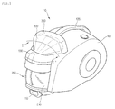
- Fig. 1 is a perspective view of a vacuum cleaner having a dust separation device according to an embodiment of the present invention.
- a vacuum cleaner 10 includes a main body 100 and a dust separation device for separating and storing dusts contained in air sucked into the main body 100.
- a suction nozzle (not shown) for sucking the air containing the dusts and a connection pipe for connecting the suction nozzle to the main body 100.
- a main body suction portion 110 communicating with the suction nozzle is formed on a front-lower portion of the main body 100.
- a main body discharge portion (not shown) through which the air whose dusts are separated is formed on a side of the main body 100.
- a main body handle is formed on a top of the main body 100 for the user convenience.
- the dust separation device includes a dust collection unit for storing the dusts contained in the air and a cyclone separation unit 300 for separating the dusts contained in the air sucked into the main body 100 using a cyclone principle.
- the cyclone separation unit 300 is provided in the main body 100.
- the dust collection unit 200 is detachably mounted on a front portion of the main body 100.
- a mounting/dismounting lever 130 is provided on a front-upper portion of the main body 100.
- the dust collection unit 200 functions to store the dusts separated by the cyclone separation unit 300 and to primarily separate the dusts from the air introduced in to the cyclone separation unit 300 using the cyclone principle.
- the dust collection unit 200 includes a dust collection body 210 generating the cyclone current and provided with a dust storing portion in which the dusts separated by the cyclone current are stored.
- the dust collection body 210 becomes a primary cyclone unit and the cyclone separation unit 300 becomes a secondary cyclone unit.
- a cover member 310 for at least partly enclosing an outer circumference of the cyclone separation unit 300 is provided in the main body 100.
- the dust collection unit 200 is detachably mounted on the main body 100 and communicates with the cyclone separation unit 300 as the dust collection unit 200 is mounted in the main body 100.
- the cyclone separation unit 300 includes a plurality of cone-shaped small cyclones 301 arranged fanwise.
- the cyclone separation unit 300 is provided on a front-upper portion of the main body 100. That is, the cyclone separation unit 300 is comprised of the plurality of the small cyclones 301.
- a connection passage for connecting the dust collection unit 200 to the cyclone separation unit 300 is provided in the main body 100.
- the dusts separated at the cyclone separation unit 300 are stored in the dust collection unit 200.
- a dust storing portion for storing the dusts separated at the cyclone separation unit 300 are formed and separated from the dust storing portion for storing the dusts separated at the first cyclone unit.
- the dust storing portion formed in the dust collection body 210 may include a first dust storing portion for storing the dusts separated in the dust collection body 210 and a second dust storing portion for storing the dusts separated by the cyclone separation unit 300.
- the cover member 310 is detachably provided on the main body 100.
- the cover member 310 is provided with a coupling hook and the main body 100 is provided with a hook coupling portion interlocked with the coupling hook.
- the present invention is not limited to this.
- the cover member 310 may be formed of a transparent material so that the user can identify the dust separation process in the cyclone separation unit 300. Therefore, the cyclone separation unit 300 is also formed of a transparent material.
- the dusts contained in the air is primarily separated in the dust collection body 210.
- the separated dusts are stored in the dust collection body 210.
- the air whose dusts are primarily separated is discharged from the dust collection unit 200 and introduced into the main body 100. Then, the air is directed to the cyclone separation unit 300 along the connection passage provided in the main body 100.
- the dusts still contained in the air are further separated in the cyclone separation unit 300.
- the separated dusts are stored in the dust collection unit 200.
- the air whose dusts are secondarily separated flows along a passage in the main body and is finally discharged to an external side.
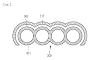
- Fig. 2 is a sectional view taken along line I-I' of Fig. 1.
- the vacuum cleaner 10 is configured to lower the vibration and noise generated during the dust separation process in the cyclone separation unit 300 using the cover member 310 at least partly enclosing the outer circumference of the cyclone separation unit 300.
- the cyclone separation unit 300 includes one or more small cyclones 301 arranged in parallel. Therefore, the air discharged from the dust collection unit 200 is separated into the small cyclones 301.
- the dust collection unit 200 and the cyclone separation unit 300 are interconnected in series.
- the air discharged from the dust collection unit 200 is directed to the cyclone separation unit 300 through the connection passage. Then, the air, as shown in Fig. 2, is separated at the inlet of the cyclone separation unit 300 and then introduced into the small cyclones 301. The dusts contained in the air introduced into the small cyclones 301 are separated therein.
- the air discharged from the dust collection unit 200 passes through the small cyclones in order but simultaneously passes through the small cyclones 301.
- the cyclone separation unit 300 is comprised of the plurality of small cyclones 301 having identical functions are arranged in parallel.
- the parallel arrangement of the small cyclones 301 includes a zigzag arrangement of the small cyclones having different sizes and shapes and a parallel arrangement of the small cyclones having different sizes and shapes.
- the air discharged from the dust collection unit 200 is simultaneously introduced into the small cyclones 301.
- the cover member 310 is formed in a shape corresponding to the cyclone separation unit 300 to at least partly enclose the outer circumference of the cyclone separation unit 300. Accordingly, the portion of the cover member 310, which encloses the cyclone separation unit 300, defines an outer surface of the main body 100.
- the vibration and noise generated during the dust separation process in the cyclone separation unit 300 can be interrupted by the cover member 310.
- the cover member 310 is formed in a shape corresponding to the cyclone separation unit 300, the outer appearance of the cleaner can be improved.
- a predetermined space 302 may be formed between the cover member 310 and the cyclone separation unit 300 to more effectively intercept the noise and vibration generated from the cyclone separation unit 300.
- the noise generated from the cyclone separation unit 300 is primarily intercepted by the space 302 and secondarily intercepted by the cover member 310. Therefore, the noise intercepting effect can be enhanced.
- cover member 310 is formed in the shape corresponding to the cyclone separation unit 300, the present invention is not limited to this embodiment.
- the cover member may be formed in a variety of shapes.
- the cover member 310 is spaced apart from the cyclone separation unit 300, the present invention is not limited to this. That is, the cover member 310 may closely contact the cyclone separation unit 300. In this case, the vibration reduction can be further improved.
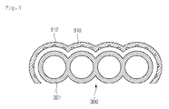
- Fig. 3 is a sectional view taken along line I-I' according to another embodiment of the present invention.
- a cover member 310 of this embodiment encloses the cyclone separation unit 300 in a state where it is spaced apart from the cyclone separation unit 300. Therefore, a space 302 is formed between the cyclone separation unit 300 and the cover member 310.
- the cover member 310 is provided at an inner surface with a plurality of noise reduction grooves 312 for reducing the noise generated ruing the dust separation process in the cyclone separation unit 300.
- noise is a longitudinal wave that returns after colliding with a wall. Therefore, when the noise generated from the cyclone separation unit 300 is directed to the noise reduction grooves 312, the noise may be confined in the noise reduction groove 312 and thus disappeared, absorbed in the noise reduction groove 312, or diffused to be compensated for each other. Therefore, the noise reduction effect can be enhanced.
- the noise is primarily reduced by the space 302 defined between the cover member 310 and the cyclone separation unit 300 and secondarily reduced by the noise reduction grooves 312. Then, the noise is thirdly reduced by the cover member 310. Therefore, the noise reduction effect can be further enhanced.
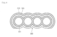
- FIG. 4 is a sectional view taken along line I-I' of FIG. 1 according to still another embodiment of the present invention.
- a cover member 310 covers an outer portion of the cyclone separation unit 300.
- a noise reduction member 320 is interposed between the cover member 310 and the cyclone separation unit 300.
- the noise reduction member 320 is formed in a shape corresponding to the cyclone separation unit 300 to enclose the outer circumference of the cyclone separation unit 300.
- the cover member 310 covers the outer side of the cyclone separation unit 300 in a state where the noise reduction member 320 encloses the outer circumference of the cyclone separation unit 300.
- the noise reduction member 320 may be formed of a sound absorption material such as a porous material or a sound shielding material for intercepting the sound.
- the noised reduction member 320 for absorbing or intercepting the noise is interposed between the cover member 310 and the cyclone separation unit 300, the noise generated from the cyclone separation unit 300 is primarily absorbed or intercepted and secondarily reduced and intercepted by the cover member 310. Furthermore, since the noise reduction member 320 is disposed to enclose the cyclone separation unit 300, the vibration generated from the cyclone separation unit 300 can be also reduced.
Landscapes
- Engineering & Computer Science (AREA)
- Mechanical Engineering (AREA)
- Filters For Electric Vacuum Cleaners (AREA)
- Electric Suction Cleaners (AREA)
Applications Claiming Priority (1)
| Application Number | Priority Date | Filing Date | Title |
|---|---|---|---|
| KR1020060040106A KR101282457B1 (ko) | 2006-05-03 | 2006-05-03 | 먼지분리기구 및 이를 구비한 진공 청소기 |
Publications (3)
| Publication Number | Publication Date |
|---|---|
| EP1852048A2 true EP1852048A2 (fr) | 2007-11-07 |
| EP1852048A3 EP1852048A3 (fr) | 2011-03-02 |
| EP1852048B1 EP1852048B1 (fr) | 2012-10-17 |
Family
ID=38377301
Family Applications (1)
| Application Number | Title | Priority Date | Filing Date |
|---|---|---|---|
| EP06125798A Not-in-force EP1852048B1 (fr) | 2006-05-03 | 2006-12-11 | Aspirateur presentant une reduction des bruits et des vibrations |
Country Status (6)
| Country | Link |
|---|---|
| EP (1) | EP1852048B1 (fr) |
| JP (1) | JP4824535B2 (fr) |
| KR (1) | KR101282457B1 (fr) |
| CN (1) | CN101066199B (fr) |
| AU (1) | AU2006249292B2 (fr) |
| RU (1) | RU2335228C1 (fr) |
Cited By (1)
| Publication number | Priority date | Publication date | Assignee | Title |
|---|---|---|---|---|
| GB2534304A (en) * | 2013-03-13 | 2016-07-20 | Techtronic Floor Care Tech Ltd | Vacuum cleaner |
Families Citing this family (1)
| Publication number | Priority date | Publication date | Assignee | Title |
|---|---|---|---|---|
| KR101480304B1 (ko) * | 2008-01-16 | 2015-01-13 | 삼성전자주식회사 | 사이클론 집진장치 및 진공청소기 |
Citations (1)
| Publication number | Priority date | Publication date | Assignee | Title |
|---|---|---|---|---|
| KR100553042B1 (ko) | 2004-12-27 | 2006-02-15 | 엘지전자 주식회사 | 진공 청소기의 집진유닛 |
Family Cites Families (10)
| Publication number | Priority date | Publication date | Assignee | Title |
|---|---|---|---|---|
| RU2019120C1 (ru) * | 1992-04-23 | 1994-09-15 | Геннадий Федосеевич Казунин | Мобильный пылеотсасывающий аппарат |
| RU2069062C1 (ru) * | 1992-07-28 | 1996-11-20 | Александр Николаевич Головин | Пылесос |
| RU2150226C1 (ru) * | 1998-04-21 | 2000-06-10 | Акционерное общество "Нижегородский машиностроительный завод" | Пылесос |
| KR100500833B1 (ko) * | 2003-05-24 | 2005-07-12 | 삼성광주전자 주식회사 | 진공청소기의 이중사이클론 집진장치 |
| KR100536506B1 (ko) * | 2003-09-09 | 2005-12-14 | 삼성광주전자 주식회사 | 사이클론 분리장치 및 이를 구비한 진공청소기 |
| KR100554237B1 (ko) * | 2003-09-08 | 2006-02-22 | 삼성광주전자 주식회사 | 사이클론 분리장치 및 이를 구비한 진공청소기 |
| KR100533830B1 (ko) * | 2004-05-14 | 2005-12-07 | 삼성광주전자 주식회사 | 다중 사이클론 집진장치 |
| KR100554238B1 (ko) * | 2004-11-15 | 2006-02-22 | 삼성광주전자 주식회사 | 사이클론 집진장치 |
| KR100546629B1 (ko) * | 2005-01-04 | 2006-01-26 | 엘지전자 주식회사 | 진공 청소기의 집진장치 |
| GB2423037A (en) * | 2005-02-15 | 2006-08-16 | Techtronic Ind Co Ltd | Cyclonic separator for suction cleaner |
-
2006
- 2006-05-03 KR KR1020060040106A patent/KR101282457B1/ko not_active Expired - Fee Related
- 2006-12-11 CN CN2006101688480A patent/CN101066199B/zh not_active Expired - Fee Related
- 2006-12-11 AU AU2006249292A patent/AU2006249292B2/en not_active Ceased
- 2006-12-11 JP JP2006333685A patent/JP4824535B2/ja not_active Expired - Fee Related
- 2006-12-11 RU RU2006143775/11A patent/RU2335228C1/ru not_active IP Right Cessation
- 2006-12-11 EP EP06125798A patent/EP1852048B1/fr not_active Not-in-force
Patent Citations (1)
| Publication number | Priority date | Publication date | Assignee | Title |
|---|---|---|---|---|
| KR100553042B1 (ko) | 2004-12-27 | 2006-02-15 | 엘지전자 주식회사 | 진공 청소기의 집진유닛 |
Cited By (1)
| Publication number | Priority date | Publication date | Assignee | Title |
|---|---|---|---|---|
| GB2534304A (en) * | 2013-03-13 | 2016-07-20 | Techtronic Floor Care Tech Ltd | Vacuum cleaner |
Also Published As
| Publication number | Publication date |
|---|---|
| AU2006249292A1 (en) | 2007-11-22 |
| JP4824535B2 (ja) | 2011-11-30 |
| KR20070107508A (ko) | 2007-11-07 |
| CN101066199B (zh) | 2011-05-18 |
| EP1852048B1 (fr) | 2012-10-17 |
| EP1852048A3 (fr) | 2011-03-02 |
| CN101066199A (zh) | 2007-11-07 |
| RU2006143775A (ru) | 2008-06-20 |
| JP2007296316A (ja) | 2007-11-15 |
| AU2006249292B2 (en) | 2009-02-26 |
| KR101282457B1 (ko) | 2013-07-17 |
| RU2335228C1 (ru) | 2008-10-10 |
Similar Documents
| Publication | Publication Date | Title |
|---|---|---|
| US7556661B2 (en) | Dust collection unit and vacuum cleaner with same | |
| EP1857032B1 (fr) | Aspirateur avec unités cycloniques primaires et secondaires | |
| AU2004202417B2 (en) | Motor Assembly and Vacuum Cleaner having the Same | |
| US7485164B2 (en) | Dust collection unit for vacuum cleaner | |
| AU2006201236B2 (en) | Cyclone dust separating apparatus | |
| AU2005290417B2 (en) | Multi cyclone collector | |
| US8782850B2 (en) | Vacuum cleaner | |
| JP2005081137A (ja) | サイクロン分離装置およびこれを備えた真空掃除機 | |
| US20090229074A1 (en) | Dual-cyclone type dust collector and cleaner having the same | |
| CN101272722B (zh) | 真空吸尘器的集尘设备 | |
| CN113080791B (zh) | 集尘基站 | |
| KR100934668B1 (ko) | 진공 청소기의 집진장치 | |
| EP1674021B1 (fr) | Unité de collection de poussière et aspirateur comportant une telle unité | |
| EP1676514B1 (fr) | Aspirateur | |
| EP1852048B1 (fr) | Aspirateur presentant une reduction des bruits et des vibrations | |
| CN209285354U (zh) | 手持式吸尘器 | |
| KR100606795B1 (ko) | 다중 싸이클론 집진장치 | |
| KR101174915B1 (ko) | 진공 청소기의 집진 바디 구조 | |
| EP1674010A1 (fr) | Aspirateur avec dispositif de retenue pour un ensemble d'aspiration | |
| JP2004129852A (ja) | 集塵装置およびそれを用いた電気掃除機 |
Legal Events
| Date | Code | Title | Description |
|---|---|---|---|
| PUAI | Public reference made under article 153(3) epc to a published international application that has entered the european phase |
Free format text: ORIGINAL CODE: 0009012 |
|
| 17P | Request for examination filed |
Effective date: 20061213 |
|
| AK | Designated contracting states |
Kind code of ref document: A2 Designated state(s): AT BE BG CH CY CZ DE DK EE ES FI FR GB GR HU IE IS IT LI LT LU LV MC NL PL PT RO SE SI SK TR |
|
| AX | Request for extension of the european patent |
Extension state: AL BA HR MK YU |
|
| PUAL | Search report despatched |
Free format text: ORIGINAL CODE: 0009013 |
|
| AK | Designated contracting states |
Kind code of ref document: A3 Designated state(s): AT BE BG CH CY CZ DE DK EE ES FI FR GB GR HU IE IS IT LI LT LU LV MC NL PL PT RO SE SI SK TR |
|
| AX | Request for extension of the european patent |
Extension state: AL BA HR MK RS |
|
| TPAC | Observations filed by third parties |
Free format text: ORIGINAL CODE: EPIDOSNTIPA |
|
| AKY | No designation fees paid | ||
| REG | Reference to a national code |
Ref country code: DE Ref legal event code: R108 |
|
| RBV | Designated contracting states (corrected) |
Designated state(s): AT BE BG CH CY CZ DE DK EE ES FI FR GB GR HU IE IS IT LI LT LU LV MC NL PL PT RO SE SI SK TR |
|
| REG | Reference to a national code |
Ref country code: DE Ref legal event code: R108 Ref document number: 602006032478 Country of ref document: DE Effective date: 20111109 |
|
| 17Q | First examination report despatched |
Effective date: 20111227 |
|
| GRAP | Despatch of communication of intention to grant a patent |
Free format text: ORIGINAL CODE: EPIDOSNIGR1 |
|
| GRAS | Grant fee paid |
Free format text: ORIGINAL CODE: EPIDOSNIGR3 |
|
| GRAA | (expected) grant |
Free format text: ORIGINAL CODE: 0009210 |
|
| AK | Designated contracting states |
Kind code of ref document: B1 Designated state(s): AT BE BG CH CY CZ DE DK EE ES FI FR GB GR HU IE IS IT LI LT LU LV MC NL PL PT RO SE SI SK TR |
|
| REG | Reference to a national code |
Ref country code: GB Ref legal event code: FG4D |
|
| REG | Reference to a national code |
Ref country code: CH Ref legal event code: EP |
|
| REG | Reference to a national code |
Ref country code: IE Ref legal event code: FG4D |
|
| REG | Reference to a national code |
Ref country code: AT Ref legal event code: REF Ref document number: 579498 Country of ref document: AT Kind code of ref document: T Effective date: 20121115 |
|
| REG | Reference to a national code |
Ref country code: DE Ref legal event code: R096 Ref document number: 602006032478 Country of ref document: DE Effective date: 20121213 |
|
| REG | Reference to a national code |
Ref country code: AT Ref legal event code: MK05 Ref document number: 579498 Country of ref document: AT Kind code of ref document: T Effective date: 20121017 |
|
| REG | Reference to a national code |
Ref country code: NL Ref legal event code: VDEP Effective date: 20121017 |
|
| REG | Reference to a national code |
Ref country code: LT Ref legal event code: MG4D |
|
| PG25 | Lapsed in a contracting state [announced via postgrant information from national office to epo] |
Ref country code: SE Free format text: LAPSE BECAUSE OF FAILURE TO SUBMIT A TRANSLATION OF THE DESCRIPTION OR TO PAY THE FEE WITHIN THE PRESCRIBED TIME-LIMIT Effective date: 20121017 Ref country code: ES Free format text: LAPSE BECAUSE OF FAILURE TO SUBMIT A TRANSLATION OF THE DESCRIPTION OR TO PAY THE FEE WITHIN THE PRESCRIBED TIME-LIMIT Effective date: 20130128 Ref country code: NL Free format text: LAPSE BECAUSE OF FAILURE TO SUBMIT A TRANSLATION OF THE DESCRIPTION OR TO PAY THE FEE WITHIN THE PRESCRIBED TIME-LIMIT Effective date: 20121017 Ref country code: LT Free format text: LAPSE BECAUSE OF FAILURE TO SUBMIT A TRANSLATION OF THE DESCRIPTION OR TO PAY THE FEE WITHIN THE PRESCRIBED TIME-LIMIT Effective date: 20121017 Ref country code: FI Free format text: LAPSE BECAUSE OF FAILURE TO SUBMIT A TRANSLATION OF THE DESCRIPTION OR TO PAY THE FEE WITHIN THE PRESCRIBED TIME-LIMIT Effective date: 20121017 Ref country code: IS Free format text: LAPSE BECAUSE OF FAILURE TO SUBMIT A TRANSLATION OF THE DESCRIPTION OR TO PAY THE FEE WITHIN THE PRESCRIBED TIME-LIMIT Effective date: 20130217 |
|
| PG25 | Lapsed in a contracting state [announced via postgrant information from national office to epo] |
Ref country code: PL Free format text: LAPSE BECAUSE OF FAILURE TO SUBMIT A TRANSLATION OF THE DESCRIPTION OR TO PAY THE FEE WITHIN THE PRESCRIBED TIME-LIMIT Effective date: 20121017 Ref country code: GR Free format text: LAPSE BECAUSE OF FAILURE TO SUBMIT A TRANSLATION OF THE DESCRIPTION OR TO PAY THE FEE WITHIN THE PRESCRIBED TIME-LIMIT Effective date: 20130118 Ref country code: SI Free format text: LAPSE BECAUSE OF FAILURE TO SUBMIT A TRANSLATION OF THE DESCRIPTION OR TO PAY THE FEE WITHIN THE PRESCRIBED TIME-LIMIT Effective date: 20121017 Ref country code: BE Free format text: LAPSE BECAUSE OF FAILURE TO SUBMIT A TRANSLATION OF THE DESCRIPTION OR TO PAY THE FEE WITHIN THE PRESCRIBED TIME-LIMIT Effective date: 20121017 Ref country code: CY Free format text: LAPSE BECAUSE OF FAILURE TO SUBMIT A TRANSLATION OF THE DESCRIPTION OR TO PAY THE FEE WITHIN THE PRESCRIBED TIME-LIMIT Effective date: 20121017 Ref country code: LV Free format text: LAPSE BECAUSE OF FAILURE TO SUBMIT A TRANSLATION OF THE DESCRIPTION OR TO PAY THE FEE WITHIN THE PRESCRIBED TIME-LIMIT Effective date: 20121017 Ref country code: PT Free format text: LAPSE BECAUSE OF FAILURE TO SUBMIT A TRANSLATION OF THE DESCRIPTION OR TO PAY THE FEE WITHIN THE PRESCRIBED TIME-LIMIT Effective date: 20130218 |
|
| PG25 | Lapsed in a contracting state [announced via postgrant information from national office to epo] |
Ref country code: AT Free format text: LAPSE BECAUSE OF FAILURE TO SUBMIT A TRANSLATION OF THE DESCRIPTION OR TO PAY THE FEE WITHIN THE PRESCRIBED TIME-LIMIT Effective date: 20121017 |
|
| PG25 | Lapsed in a contracting state [announced via postgrant information from national office to epo] |
Ref country code: CZ Free format text: LAPSE BECAUSE OF FAILURE TO SUBMIT A TRANSLATION OF THE DESCRIPTION OR TO PAY THE FEE WITHIN THE PRESCRIBED TIME-LIMIT Effective date: 20121017 Ref country code: EE Free format text: LAPSE BECAUSE OF FAILURE TO SUBMIT A TRANSLATION OF THE DESCRIPTION OR TO PAY THE FEE WITHIN THE PRESCRIBED TIME-LIMIT Effective date: 20121017 Ref country code: SK Free format text: LAPSE BECAUSE OF FAILURE TO SUBMIT A TRANSLATION OF THE DESCRIPTION OR TO PAY THE FEE WITHIN THE PRESCRIBED TIME-LIMIT Effective date: 20121017 Ref country code: DK Free format text: LAPSE BECAUSE OF FAILURE TO SUBMIT A TRANSLATION OF THE DESCRIPTION OR TO PAY THE FEE WITHIN THE PRESCRIBED TIME-LIMIT Effective date: 20121017 Ref country code: MC Free format text: LAPSE BECAUSE OF NON-PAYMENT OF DUE FEES Effective date: 20121231 |
|
| REG | Reference to a national code |
Ref country code: CH Ref legal event code: PL |
|
| PLBE | No opposition filed within time limit |
Free format text: ORIGINAL CODE: 0009261 |
|
| STAA | Information on the status of an ep patent application or granted ep patent |
Free format text: STATUS: NO OPPOSITION FILED WITHIN TIME LIMIT |
|
| PG25 | Lapsed in a contracting state [announced via postgrant information from national office to epo] |
Ref country code: RO Free format text: LAPSE BECAUSE OF FAILURE TO SUBMIT A TRANSLATION OF THE DESCRIPTION OR TO PAY THE FEE WITHIN THE PRESCRIBED TIME-LIMIT Effective date: 20121017 |
|
| 26N | No opposition filed |
Effective date: 20130718 |
|
| REG | Reference to a national code |
Ref country code: IE Ref legal event code: MM4A |
|
| PG25 | Lapsed in a contracting state [announced via postgrant information from national office to epo] |
Ref country code: LI Free format text: LAPSE BECAUSE OF NON-PAYMENT OF DUE FEES Effective date: 20121231 Ref country code: CH Free format text: LAPSE BECAUSE OF NON-PAYMENT OF DUE FEES Effective date: 20121231 Ref country code: IE Free format text: LAPSE BECAUSE OF NON-PAYMENT OF DUE FEES Effective date: 20121211 |
|
| REG | Reference to a national code |
Ref country code: DE Ref legal event code: R097 Ref document number: 602006032478 Country of ref document: DE Effective date: 20130718 |
|
| PG25 | Lapsed in a contracting state [announced via postgrant information from national office to epo] |
Ref country code: TR Free format text: LAPSE BECAUSE OF FAILURE TO SUBMIT A TRANSLATION OF THE DESCRIPTION OR TO PAY THE FEE WITHIN THE PRESCRIBED TIME-LIMIT Effective date: 20121017 |
|
| PG25 | Lapsed in a contracting state [announced via postgrant information from national office to epo] |
Ref country code: LU Free format text: LAPSE BECAUSE OF NON-PAYMENT OF DUE FEES Effective date: 20121211 |
|
| PG25 | Lapsed in a contracting state [announced via postgrant information from national office to epo] |
Ref country code: HU Free format text: LAPSE BECAUSE OF FAILURE TO SUBMIT A TRANSLATION OF THE DESCRIPTION OR TO PAY THE FEE WITHIN THE PRESCRIBED TIME-LIMIT Effective date: 20061211 |
|
| PG25 | Lapsed in a contracting state [announced via postgrant information from national office to epo] |
Ref country code: BG Free format text: LAPSE BECAUSE OF NON-PAYMENT OF DUE FEES Effective date: 20121017 |
|
| REG | Reference to a national code |
Ref country code: FR Ref legal event code: PLFP Year of fee payment: 10 |
|
| REG | Reference to a national code |
Ref country code: FR Ref legal event code: PLFP Year of fee payment: 11 |
|
| PGFP | Annual fee paid to national office [announced via postgrant information from national office to epo] |
Ref country code: FR Payment date: 20161114 Year of fee payment: 11 Ref country code: GB Payment date: 20161110 Year of fee payment: 11 |
|
| PGFP | Annual fee paid to national office [announced via postgrant information from national office to epo] |
Ref country code: IT Payment date: 20161215 Year of fee payment: 11 |
|
| GBPC | Gb: european patent ceased through non-payment of renewal fee |
Effective date: 20171211 |
|
| REG | Reference to a national code |
Ref country code: FR Ref legal event code: ST Effective date: 20180831 |
|
| PG25 | Lapsed in a contracting state [announced via postgrant information from national office to epo] |
Ref country code: FR Free format text: LAPSE BECAUSE OF NON-PAYMENT OF DUE FEES Effective date: 20180102 Ref country code: IT Free format text: LAPSE BECAUSE OF NON-PAYMENT OF DUE FEES Effective date: 20171211 |
|
| PG25 | Lapsed in a contracting state [announced via postgrant information from national office to epo] |
Ref country code: GB Free format text: LAPSE BECAUSE OF NON-PAYMENT OF DUE FEES Effective date: 20171211 |
|
| PGFP | Annual fee paid to national office [announced via postgrant information from national office to epo] |
Ref country code: DE Payment date: 20220615 Year of fee payment: 17 |
|
| REG | Reference to a national code |
Ref country code: DE Ref legal event code: R119 Ref document number: 602006032478 Country of ref document: DE |
|
| PG25 | Lapsed in a contracting state [announced via postgrant information from national office to epo] |
Ref country code: DE Free format text: LAPSE BECAUSE OF NON-PAYMENT OF DUE FEES Effective date: 20240702 |
|
| PG25 | Lapsed in a contracting state [announced via postgrant information from national office to epo] |
Ref country code: DE Free format text: LAPSE BECAUSE OF NON-PAYMENT OF DUE FEES Effective date: 20240702 |