EP1852131B1 - Wasserspender mit Desinfektionskreislauf - Google Patents
Wasserspender mit Desinfektionskreislauf Download PDFInfo
- Publication number
- EP1852131B1 EP1852131B1 EP07251878A EP07251878A EP1852131B1 EP 1852131 B1 EP1852131 B1 EP 1852131B1 EP 07251878 A EP07251878 A EP 07251878A EP 07251878 A EP07251878 A EP 07251878A EP 1852131 B1 EP1852131 B1 EP 1852131B1
- Authority
- EP
- European Patent Office
- Prior art keywords
- water
- hot water
- reservoir
- flow line
- dispense
- Prior art date
- Legal status (The legal status is an assumption and is not a legal conclusion. Google has not performed a legal analysis and makes no representation as to the accuracy of the status listed.)
- Not-in-force
Links
Images



Classifications
-
- B—PERFORMING OPERATIONS; TRANSPORTING
- B67—OPENING, CLOSING OR CLEANING BOTTLES, JARS OR SIMILAR CONTAINERS; LIQUID HANDLING
- B67D—DISPENSING, DELIVERING OR TRANSFERRING LIQUIDS, NOT OTHERWISE PROVIDED FOR
- B67D1/00—Apparatus or devices for dispensing beverages on draught
- B67D1/07—Cleaning beverage-dispensing apparatus
-
- A—HUMAN NECESSITIES
- A61—MEDICAL OR VETERINARY SCIENCE; HYGIENE
- A61L—METHODS OR APPARATUS FOR STERILISING MATERIALS OR OBJECTS IN GENERAL; DISINFECTION, STERILISATION OR DEODORISATION OF AIR; CHEMICAL ASPECTS OF BANDAGES, DRESSINGS, ABSORBENT PADS OR SURGICAL ARTICLES; MATERIALS FOR BANDAGES, DRESSINGS, ABSORBENT PADS OR SURGICAL ARTICLES
- A61L2/00—Disinfection or sterilisation of materials or objects, in general; Accessories therefor
- A61L2/02—Disinfection or sterilisation of materials or objects, in general; Accessories therefor using physical processes
- A61L2/04—Heat
-
- A—HUMAN NECESSITIES
- A61—MEDICAL OR VETERINARY SCIENCE; HYGIENE
- A61L—METHODS OR APPARATUS FOR STERILISING MATERIALS OR OBJECTS IN GENERAL; DISINFECTION, STERILISATION OR DEODORISATION OF AIR; CHEMICAL ASPECTS OF BANDAGES, DRESSINGS, ABSORBENT PADS OR SURGICAL ARTICLES; MATERIALS FOR BANDAGES, DRESSINGS, ABSORBENT PADS OR SURGICAL ARTICLES
- A61L2/00—Disinfection or sterilisation of materials or objects, in general; Accessories therefor
- A61L2/02—Disinfection or sterilisation of materials or objects, in general; Accessories therefor using physical processes
- A61L2/04—Heat
- A61L2/06—Hot gas
- A61L2/07—Steam
-
- B—PERFORMING OPERATIONS; TRANSPORTING
- B67—OPENING, CLOSING OR CLEANING BOTTLES, JARS OR SIMILAR CONTAINERS; LIQUID HANDLING
- B67D—DISPENSING, DELIVERING OR TRANSFERRING LIQUIDS, NOT OTHERWISE PROVIDED FOR
- B67D3/00—Apparatus or devices for controlling flow of liquids under gravity from storage containers for dispensing purposes
- B67D3/0009—Apparatus or devices for controlling flow of liquids under gravity from storage containers for dispensing purposes provided with cooling arrangements
-
- B—PERFORMING OPERATIONS; TRANSPORTING
- B67—OPENING, CLOSING OR CLEANING BOTTLES, JARS OR SIMILAR CONTAINERS; LIQUID HANDLING
- B67D—DISPENSING, DELIVERING OR TRANSFERRING LIQUIDS, NOT OTHERWISE PROVIDED FOR
- B67D3/00—Apparatus or devices for controlling flow of liquids under gravity from storage containers for dispensing purposes
- B67D3/0022—Apparatus or devices for controlling flow of liquids under gravity from storage containers for dispensing purposes provided with heating arrangements
-
- B—PERFORMING OPERATIONS; TRANSPORTING
- B67—OPENING, CLOSING OR CLEANING BOTTLES, JARS OR SIMILAR CONTAINERS; LIQUID HANDLING
- B67D—DISPENSING, DELIVERING OR TRANSFERRING LIQUIDS, NOT OTHERWISE PROVIDED FOR
- B67D3/00—Apparatus or devices for controlling flow of liquids under gravity from storage containers for dispensing purposes
- B67D3/0029—Apparatus or devices for controlling flow of liquids under gravity from storage containers for dispensing purposes provided with holders for bottles or similar containers
-
- B—PERFORMING OPERATIONS; TRANSPORTING
- B67—OPENING, CLOSING OR CLEANING BOTTLES, JARS OR SIMILAR CONTAINERS; LIQUID HANDLING
- B67D—DISPENSING, DELIVERING OR TRANSFERRING LIQUIDS, NOT OTHERWISE PROVIDED FOR
- B67D2210/00—Indexing scheme relating to aspects and details of apparatus or devices for dispensing beverages on draught or for controlling flow of liquids under gravity from storage containers for dispensing purposes
- B67D2210/00002—Purifying means
- B67D2210/00013—Sterilising means
-
- B—PERFORMING OPERATIONS; TRANSPORTING
- B67—OPENING, CLOSING OR CLEANING BOTTLES, JARS OR SIMILAR CONTAINERS; LIQUID HANDLING
- B67D—DISPENSING, DELIVERING OR TRANSFERRING LIQUIDS, NOT OTHERWISE PROVIDED FOR
- B67D2210/00—Indexing scheme relating to aspects and details of apparatus or devices for dispensing beverages on draught or for controlling flow of liquids under gravity from storage containers for dispensing purposes
- B67D2210/00002—Purifying means
- B67D2210/00013—Sterilising means
- B67D2210/00026—Heaters
-
- C—CHEMISTRY; METALLURGY
- C02—TREATMENT OF WATER, WASTE WATER, SEWAGE, OR SLUDGE
- C02F—TREATMENT OF WATER, WASTE WATER, SEWAGE, OR SLUDGE
- C02F2307/00—Location of water treatment or water treatment device
- C02F2307/10—Location of water treatment or water treatment device as part of a potable water dispenser, e.g. for use in homes or offices
Definitions
- This invention relates to water dispensers and in particular to bottled waster dispensers as set from in the preamble of claim 1.
- a dispenser is known from US-A-6 201 046 . More specifically, the invention concerns disinfection of bottled water dispensers to improve bacteriological quality of the dispensed water.
- Bottled water dispensers for dispensing chilled water are well known in which a reservoir is supplied with water from a bottle that is inverted to connect the bottle to an inlet of the reservoir. In use, water in the reservoir is cooled to a desired temperature for dispense and delivered to an outlet for dispense into a glass, cup or similar vessel. The dispensed water is replaced by water from the bottle and, when the bottle is empty it can be detached and replaced by a full bottle.
- a problem with these types of dispensers is that the water contained in the bottle contains bacteria which are introduced into the dispenser where the bacteria can rapidly grow with the result that the bacteriological quality of the dispensed water deteriorates with time. This can also lead to formation of a bio-film on internal surfaces of the dispenser that leads to rapid growth of bacteria when the bottle is removed and replaced by a new bottle.
- US-5766453-A discloses a system that employs reverse osmosis purification or a cartridge filter arrangement
- CA-2101212-A1 disposes a system in which a refrigerated water container directly supplies a cold water tank and a hot water tank for subsequent dispense.
- a pipe connects the tanks for circulating hot water in a sterilisation process independently of the flow delivery lines.
- WO-2005/06834-A discloses a system in which a hot water tank and cold water tank are directly supplied by a water container and a pipe connects the tanks circulating hot water in a sterilisation process independently of the hot water flow delivery line.
- US-5290442-A discloses a system in which a cold water tank is filled by connection to a mains supply.
- the tank can be kept in the fridge for dispense of cold water that is filtered before delivery.
- WO-95/11854 -A discloses a system in which a cleaning fluid is introduced and circulated in the system.
- DE-80938-C discloses a system in which a cleaning/rinsing agent is introduced to the system.
- the present invention has been made from a consideration of the foregoing problem.
- the invention provides a bottled water dispenser as defined in claim 1.
- the bacteriological quality of the dispensed water can be improved by disinfection of internal surfaces of the dispenser.
- the disinfection cycle can be activated automatically, for example with a programmable electronic controller or microprocessor.
- disinfection is effected using steam or hot water generated in the hot water reservoir to disinfect the cold water reservoir.
- disinfection is effected using steam or hot water generated in an auxiliary heater located in the circulation flow line to disinfect the cold water reservoir.
- disinfection is effected using steam or hot water generated in the hot water reservoir and an auxiliary heater located in the circulation flow line to disinfect the cold water reservoir.
- the circulation flow line is preferably connected to a cooling means whereby the hot water or steam can be cooled at the end of the disinfection cycle before re-activating a refrigeration circuit for cooling the water in the cold water reservoir.
- the dispense flow line from the cold water reservoir includes a micro-filter to remove bacteria contained in the water prior to dispense.
- the micro-filter is detachable and can be replaced at pre-determined intervals to maintain effectiveness of the filter. For example, replacement of the filter may be determined according to the length of time the filter has been in place or the volume of water that has passed through the filter.
- Appropriate sensors may be employed to provide a warning when the filter needs to be replaced. Such warning may include a visual and/or audible warning at the dispenser. Alternatively or additionally, such warning may be transmitted to a remote monitoring station to initiate a service call by a maintenance engineer to replace the filter.
- the flow line includes a by-pass for the filter to reduce the amount of water that is re-circulated through the filter during the disinfection cycle. In this way, the life of the filter may be extended.
- the dispense outlets are adapted to inhibit growth of bacteria back into the dispense system caused by contamination of the outlets from human contact or from some other source such as airborne bacteria.
- the dispense outlets may be provided with a coating of silver ions and/or exposed to UV radiation to kill bacteria coming into contact with the outlets.
- the outlets may be configured as described in our European patent application No.1440941 .
- the dispenser can dispense cold or hot water as desired.
- the dispensed water may be mixed with other beverage ingredients to produce a desired cold or hot beverage.
- the other ingredients may be added separately to the receptacle into which the water is dispensed by the user.
- the dispenser may be adapted to mix selected ingredients with the water for dispense of the desired beverage, for example by user selection at an interface panel.
- the dispense of water may be manually controlled or automatically controlled.
- a manually operable dispense valve may be employed or an electrically operable valve may be employed with a flowmeter or timer to dispense a known volume of water.
- the invention provides a method for disinfecting the internal surfaces of a bottled water dispenser with steam or hot water as defined in claim 12. Such a method inhibits growth of bacteria in use of the dispenser.
- steam or hot water generated in the dispenser can be employed during the disinfection cycle.
- a bottled water dispenser 1 not according to the invention having a water dispensing system including a cold water reservoir 3 and a hot water reservoir 5.
- the cold water reservoir 3 is configured at the upper end to support a bottle of water (not shown) in an inverted position with an outlet from the bottle detachably connected to an inlet 7 for supplying water to the cold water reservoir 3.
- the inlet 7 is arranged to admit water to the cold water reservoir 3 and air to the bottle when the water level in the cold water reservoir 3 falls below a pre-determined level. In this way, water dispensed from the system is automatically replenished with water from the bottle.
- the bottle is typically made of clear glass or plastics and is of a size that can be readily handled, for example, the bottle may contain five gallons (approximately 20 litres) of water. It will be understood that the size (volume) of the bottle may be changed.
- the bottle will be visible so that the level of water in the bottle can be inspected and the bottle removed when empty and replaced by a full bottle. It will be understood this is not essential, however, and other means of monitoring the water level in the bottle can be employed to generate a signal when the bottle needs to be replaced.
- the signal may be visual and/or audible.
- the water in the cold water reservoir 3 is cooled by any suitable means such as a refrigeration circuit including an evaporator 9 wrapped around the reservoir 3 to maintain the water in the reservoir 3 at a desired temperature for dispense such as 5-10 °C.
- a refrigeration circuit including an evaporator 9 wrapped around the reservoir 3 to maintain the water in the reservoir 3 at a desired temperature for dispense such as 5-10 °C.
- the temperature of the water in the reservoir 3 may be monitored by a temperature sensor (not shown) with operation of the refrigeration circuit being controlled in response to the temperature of the water in the reservoir 3.
- the cold water reservoir 3 is connected to a dispense outlet 11 via a water flow line 13 including an on/off valve 15 for controlling dispense of cold water from the outlet 11 into a receptacle such as a glass or cup placed under the outlet 11.
- the valve 15 may be an electrically operated valve, for example a solenoid valve, controlled via a user interface panel (not shown) on the dispenser. Alternatively, the valve may be a manually operated valve controlled via a handle or lever accessible to the user.
- the cold water reservoir 3 is also connected to the hot water reservoir 5 via a water flow line 17 for supplying cold water to the hot water reservoir 5.
- the water in the hot water reservoir 5 is heated by any suitable means such as a heating circuit including an electrical heater 19 wrapped around the reservoir 5 to maintain the water in the reservoir 5 at a desired temperature for dispense such as 70-90°C.
- a heating circuit including an electrical heater 19 wrapped around the reservoir 5 to maintain the water in the reservoir 5 at a desired temperature for dispense such as 70-90°C.
- the temperature of the water in the reservoir 5 may be monitored by a temperature sensor (not shown) with operation of the heating circuit being controlled in response to the temperature of the water in the reservoir 5.
- the hot water reservoir 5 is connected to a dispense outlet 21 via a water flow line 23 including an on/off valve 25 for controlling dispense of hot water from the outlet 21 into a receptacle such as a glass or cup placed under the outlet 21.
- the valve 25 may be an electrically operated valve, for example a solenoid valve, controlled via a user interface panel (not shown) on the dispenser. Alternatively, the valve may be a manually operated valve controlled via a handle or lever accessible to the user.
- the hot water reservoir 5 is also provided with a drain outlet 27 having a valve (not shown) that is normally closed and can be opened when it is desired to empty the water dispenser 1.
- the drain valve may be a manually operable valve or an electrically operable valve.
- a water overflow line 29 connects the hot water reservoir 5 to the space above the water level in the cold water reservoir 3 to equalise the pressure in the system.
- the water dispenser 1 can dispense cold or hot water as desired.
- the dispensed water may be mixed with other beverage ingredients to produce a desired cold or hot beverage.
- the other ingredients may be added separately to the receptacle into which the water is dispensed by the user.
- the dispenser may be adapted to mix selected ingredients with the water for dispense of the desired beverage, for example by user selection at an interface panel.
- the bacteriological quality of the dispensed water is affected by the levels of bacteria in the stored water contained in the bottle and in the water dispensing system of the water dispenser 1. If left uncontrolled, rapid growth of bacteria can occur leading to off-taste and health risks when drinking the dispensed water, especially from the cold water reservoir where bio-film can build-up on internal surfaces of the reservoir 3 and the water flow lines to the outlet 11 and to the hot water reservoir 5. Growth of bacteria is less of a problem in water dispensed from the hot water reservoir 5 where the water is heated and maintained at an elevated temperature sufficient to inhibit growth or kill bacteria already present in the water.
- Growth of bacteria in the water dispensing system can be controlled by carrying out a disinfection cycle using steam generated in the hot water reservoir 5.
- the water bottle is detached from the inlet 7 and a closure cap fitted to the inlet 7.
- the cooling circuit for the cold water reservoir 3 is de-activated and water is drained from the cold water reservoir 3 and the flow lines 13,23.
- the hot water reservoir 5 is partially emptied to leave a space above the water level in the hot water reservoir 5.
- the dispense outlets 11 and 21 are then temporarily connected with a length of tubing (not shown) or the like and the valves 15,25 opened.
- the disinfection cycle is then activated, for example via a control panel located within the dispenser 1 or otherwise adapted for restricted access and operation by authorised personnel only.
- water in the hot water reservoir is heated to generate steam that is then circulated in the system.
- the heating circuit for the hot water reservoir 5 may be provided with an auxiliary heater (not shown) to boost temporarily the power input for heating rapidly the water in the hot water reservoir 5 to generate the steam.
- the steam contacts the internal surfaces of the flow lines, the cold water reservoir and the inlet to render any bio-film on the surfaces inactive.
- the duration of the disinfection cycle may be controlled manually or automatically, for example by a timer control circuit to circulate steam for a pre-determined length of time.
- the heating circuit is switched off, the valves 15,25 closed, the tubing connecting the outlets 11,21 removed, and the water bottle or a new water bottle connected to the inlet 7 to re-fill the water dispensing system.
- the disinfection cycle may be carried out at regular intervals, for example by a service technician.
- steam for the disinfection cycle may be generated by heating water in an auxiliary heater temporarily connected between the outlets 11,21 during the disinfection cycle.
- FIG. 2 another bottled water dispenser 101 not according to the invention is shown in which like reference numerals in the series 100 are used to indicate parts corresponding to the first embodiment.
- the water flow line 113 from the cold water reservoir 103 to the dispense outlet 111 includes a pump 131 and a micro-filter 133.
- the pump 131 is operable during the disinfection cycle described later and the micro-filter 133 is operable to remove bacteria from water dispensed via the outlet 111 from the cold water reservoir 103. By removing bacteria from the dispensed water, the bacteriological quality of the dispensed water is improved.
- the micro-filter 133 may be of any suitable type such as a membrane filter available from Filtrix.
- a micro-filter may be provided in the flow line from the cold water reservoir in the first embodiment described above.
- the disinfection cycle is effected by circulating hot water around the water dispensing system. This may be carried out with the water bottle in situ or with the water bottle detached and the closure cap fitted to the inlet 107.
- the dispense outlets 111,121 are again temporarily connected by a length of tubing (not shown) which includes an auxiliary heater (not shown) for heating water flowing through the tubing.
- the auxiliary heater comprises a heat exchanger tank containing an electrical heating element for heating the water as it passes through the tank.
- the auxiliary heater will have a higher power rating than the heating circuit for the hot water reservoir to ensure rapid heating of the water to the required temperature for the disinfection cycle. In this way, the time for the water to reach the required temperature can be reduced.
- the on-site time of the service technician may be reduced.
- the disinfection cycle is then activated, for example via a control panel located within the dispenser 101 or otherwise adapted for restricted access and operation by authorised personnel only.
- the cooling circuit for the cold water reservoir 103 is switched off, the valves 115,125 are opened and the pump 131 is operable to circulate water around the water dispensing system from the cold water reservoir 103 to the hot water reservoir 105 and back to the cold water reservoir 103.
- the pump 131 may operate continuously during the disinfection cycle.
- the pump 131 is operable intermittently, i.e. cycles between on and off conditions, during the disinfection cycle. The times the pump is on and off may be preset or responsive to a sensor according to the operating conditions of the disinfection cycle.
- the circulating water is heated to an elevated temperature by the heater temporarily connected between the dispense outlets 111,121 via the tubing and is circulated around the water dispensing system for a time sufficient to kill bacteria in the water and render any bio-film on the internal surfaces inactive.
- the duration of the disinfection cycle may be controlled manually or automatically, for example by a timer control circuit to circulate steam for a pre-determined length of time.
- the pump 131 and the auxiliary heater between the outlets 111,121 are switched off, the valves 115,125 closed and the tubing connecting the outlets 111,121 removed together with the auxiliary heater.
- the hot water remaining in the cold water reservoir 103 at the end of the disinfection cycle may be left to cool down naturally before re-activating the refrigeration circuit to cool the water to the desired dispense temperature.
- the outlet 111 may be opened to dispense the hot water from the cold water reservoir 103 and re-fill the cold water reservoir from the water bottle connected to the inlet 107.
- the disinfection cycle may be carried out at regular intervals, for example by a service technician.
- the external heater connected between the outlets for heating the water during the disinfection cycle may be omitted and the water heated to the required temperature in the hot water reservoir 105.
- the heating circuit for the hot water reservoir 105 may be provided with an auxiliary heater to boost temporarily the power input for heating rapidly the water in the hot water reservoir 105 for the disinfection cycle.
- the disinfection cycle requires the presence of a service technician or the like to set up the water dispenser for the disinfection cycle by temporarily connecting the outlets from the hot and cold reservoirs.
- a first embodiment of a bottled water dispenser 201 according to the invention is shown in which like reference numerals in the series 200 are used to indicate parts corresponding to the previous embodiments.
- the water dispensing system is configured to enable the disinfection cycle to be automatically activated, for example overnight by employing three-way valves 215,225 in the flow lines 213,223 that can be switched between a dispense position for delivering water from the reservoirs 203,205 to the respective outlets 211,221 for dispense, and a disinfection position for circulating hot water around the water dispensing system via a water flow line 235 connecting the flow lines 213,223 during the disinfection cycle.
- the valves 215,225 can be open or closed.
- the hot water for the disinfection cycle is generated in the hot water reservoir 205 and the heating circuit for the hot water reservoir 205 may be provided with an auxiliary heater to boost temporarily the power input for heating rapidly the water in the hot water reservoir 105 for the disinfection cycle.
- the water heating circuit is switched off and the circulating water is diverted through an air cooled heat exchanger 239 by switching valve 225 to the dispense position and opening an on-off valve 241 in a water flow line 237 extending between the flow line 235 and the flow line 217.
- the on/off valve 241 is closed during the disinfection cycle and is open during the cool-down cycle.
- a programmable controller (not shown) is provided for controlling the disinfection cycle such that the timing and duration of the disinfection cycle can be set to take place automatically, for example overnight.
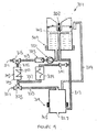
- FIG. 4 a second embodiment of a bottled water dispenser 301 according to the invention is shown in which like reference numerals in the series 300 are used to indicate parts corresponding to the previous embodiments.
- an auxiliary heater 343 is provided in the flow line 335 for heating the circulating water during the disinfection cycle.
- the heater 343 comprises a heat exchanger tank 345 containing an electrical heating element 347 for heating the water as it flows through the tank 345.
- the auxiliary heater will have a higher power rating than the heating circuit for the hot water reservoir to ensure rapid heating of the water to the required temperature for the disinfection cycle.
- the construction and operation of this embodiment is similar to and will be understood from the description of Figure 3 .
- FIG. 5 a third embodiment of a bottled water dispenser 401 according to the invention is shown in which like reference numerals in the series 400 are used to indicate parts corresponding to the previous embodiments.
- a water bottle 449 is shown inverted and connected to the inlet 407 of the cold water reservoir.
- the flow lines 413,423 are connected to a common outlet 451 for selectively dispensing cold or hot water according to actuation of the valves 415,425 during normal operation of the water dispenser in the dispense mode in which on-off valve 441 in flow line 437 is closed and an on-off valve 453 in the flow line 435 connecting the flow lines 413,423 is closed.
- Pump 431 in cold water flow line 413 and a pump 455 in hot water flow line 423 may be operable in response to actuation of a dispense to assist water flow during dispense.
- valves 415,425 are closed and valve 453 is opened to connect the flow lines 413,423.
- Valve 441 is also closed and water heated in the hot water reservoir 405 to a temperature sufficient to kill bacteria is circulated around the system by operating pump 431 continuously or intermittently as described previously.
- an auxiliary heater (not shown) may be employed in the circulation flow line 435 to heat the water during the disinfection cycle.
- pump 455 is switched-off and a valve 457 in by-pass line 459 opened to allow circulating water to by-pass the pump 455.
- a similar by-pass may be provided for the micro-filter 433 to reduce the amount of water flowing through the filter 433 during the disinfection cycle and thereby extend the life of the filter.
- the valve 441 is opened to circulate the hot water through the heat exchanger 439 to cool the water before re-activating the cooling circuit to chill the water in the cold water reservoir 403.
- the operation of this embodiment is similar to and will be understood from the description of Figures 3 and 4 .
- the first to third embodiments of the bottled water dispenser may be adapted so as to be operable to carry out the disinfection cycle using steam generated in the hot water reservoir and/or in the auxiliary heater where provided.
- the present invention provides a bottled water dispenser for dispensing hot or cold water in which growth of bacteria in the dispensed water can be controlled to improve the bacteriological quality of the dispensed water by regular disinfection of the water dispensing system with hot water or steam circulated in the system and/or by removal of bacteria from the water by a micro-filter.
- the circulation of steam or hot water during the disinfection cycle is effective to render inactive any bio-film that has developed on the internal surfaces of the system.
- the rate of growth of bacteria in the water between successive disinfection cycles is reduced thereby improving the bacteriological quality of the dispensed water.
- the dispenser has a built-in disinfection unit and can be programmed to carry out the disinfection cycle automatically when required.
- the water dispenser can be regularly disinfected, for example overnight, such that undesirable formation of a bio-film on the internal surfaces of the system is inhibited thereby reducing any build-up of bio-film leading to an improvement in water quality.
- all the above-described embodiments may benefit from an active sanitisation with chemicals at pre-determined intervals to remove completely any bio-film that has collected on the internal surfaces of the system.
- the time interval between such active sanitisations may be increased in the embodiments with built-in disinfection units which can be operated without the presence of service personnel.
- the outlets may be adapted to prevent growth of bacteria back into the water dispense system.
- the outlets may be coated with silver ions and/or be exposed to a UV source to kill bacteria present from human contact with the outlets or from some other source of bacteria.
- a UV source in the cold water reservoir or elsewhere (e.g. in the bottle) to kill bacteria present in the water.
- pumps provided in the cold and hot water flow lines of Figure 5 to assist dispense may be employed in any of the other embodiments.
- the pump in the hot water flow line of Figure 5 may be omitted and the pump in the cold water flow line used during the disinfection cycle only as described in the other embodiments.
- a single outlet for hot and cold water as shown in Figure 5 may be employed in any of the other embodiments.
Landscapes
- Health & Medical Sciences (AREA)
- Engineering & Computer Science (AREA)
- Mechanical Engineering (AREA)
- General Health & Medical Sciences (AREA)
- Life Sciences & Earth Sciences (AREA)
- Animal Behavior & Ethology (AREA)
- Epidemiology (AREA)
- Public Health (AREA)
- Veterinary Medicine (AREA)
- Devices For Dispensing Beverages (AREA)
- Apparatus For Disinfection Or Sterilisation (AREA)
- Agricultural Chemicals And Associated Chemicals (AREA)
- Air Bags (AREA)
- Telephone Function (AREA)
Claims (15)
- Wasserspender für in Flaschen befindliches Wasser mit einem Wasserausgabesystem für eine lösbare Verbindung an eine das auszugebende Wasser enthaltende Flasche (449), wobei das System ein Kaltwasserreservoir (203;303;403) umfasst, welches geeignet ist, Kaltwasser zu liefern, einem Heißwasserreservoir (205;305;405), welches Mittel (219;319;419) zum Erhitzen des Wassers umfasst, und geeignet ist, Heißwasser zu liefern, einer Ausgabeströmungsleitung (213;313;413) von dem Kaltwasserreservoir (203;303;403) zu einem Auslass (211;311;411) zum Ausgeben von kaltem Wasser, einer Ausgabeströmungsleitung (223;323;423) von dem Heißwasserreservoir zu einem Auslass (221;321;421) zur Ausgabe von Heißwasser, dadurch gekennzeichnet, dass das Kaltwasserreservoir (203;303;403) an einem oberen Ende zum Tragen einer Wasserflasche (449) in einer umgekehrten Position ausgebildet ist, wobei ein Auslass von der Flasche (449) abnehmbar an einem Einlass (207;307;407) des Kaltwasserreservoirs (203;303;403) angeschlossen ist, um Wasser zu dem Kaltwasserreservoir (203;303;403) zuzuführen, eine Versorgungsleitung (217;317;417), welche das Kaltwasserreservoir (203;303;403) mit dem Heißwasserreservoir (205;305;405 verbindet, um Wasser von dem Kaltwasserreservoir (203;303;403) zu dem Heißwasserreservoir (5;105;205;305;405) zuzuführen, eine Zirkulationsströmungsleitung (235;335;435), welche die Kaltwasserausgabeströmungsleitung (213;313;413) mit der Heißwasserausgabeströmungsleitung (223;323;423) verbindet, und Ventilmittel (215,225;315,325;453), um zeitweilig die Zirkulationsströmungsleitung (235;335;435) zu öffnen, um die Ausgabeströmungsleitungen (213,223;313,323;413,423) zu verbinden, um Dampf oder Heißwasser in dem System während des Desinfektionszyklus zirkulieren zu lassen und zum Schließen der Zirkulationsströmungsleitung (235;335;435).
- Wasserspender für in Flaschen befindliches Wasser nach Anspruch 1, dadurch gekennzeichnet, dass ein Mittel vorgesehen ist, um den Desinfektionszyklus zu steuern.
- Wasserspender für in Flaschen befindliches Wasser nach Anspruch 1 oder 2, dadurch gekennzeichnet, dass eine Hilfsheizung (343) in der Zirkulationsströmungsleitung (335) angeordnet ist, um während des Desinfektionszyklus Dampf oder Heißwasser zu erzeugen.
- Wasserspender für in Flaschen befindliches Wasser nach einem der vorstehenden Ansprüche, dadurch gekennzeichnet, dass die Zirkulationsströmungsleitung (235;335) an ein Kühlmittel (239;339) angeschlossen ist, um Heißwasser oder Dampf, die für den Desinfektionszyklus verwendet wurden, zu kühlen.
- Wasserspender für in Flaschen befindliches Wasser nach einem der vorstehenden Ansprüche, dadurch gekennzeichnet, dass die Ausgabeströmungsleitung (113;213;313) von dem Kaltwasserreservoir (103;203;303) einen Mikrofilter (133;233;333) umfasst, um im Wasser enthaltene Bakterien vor der Ausgabe zu entfernen.
- Wasserspender für in Flaschen befindliches Wasser nach Anspruch 5, dadurch gekennzeichnet, dass der Mikrofilter (133;233;333) abnehmbar ist, und dass ein Sensormittel verwendet wird, um eine Warnung zu erzeugen, wenn der Filter ersetzt werden muss.
- Wasserspender für in Flaschen befindliches Wasser nach Anspruch 6, dadurch gekennzeichnet, dass ein Bypass vorgesehen ist, um während des Desinfektionszyklus den Filter zu umgehen.
- Wasserspender für in Flaschen befindliches Wasser nach einem der vorstehenden Ansprüche, dadurch gekennzeichnet, dass eine Pumpe (231;331;431) in der Kaltwasserausgabeströmungsleitung (213;313;413) vorgesehen ist, um das Wasser während des Desinfektionszyklus zu zirkulieren.
- Wasserspender für in Flaschen befindliches Wasser nach Anspruch 8, wobei die Ausgabe von Kaltwasser während des Normalbetriebs durch die Pumpe (231;331;431) unterstützt ist.
- Wasserspender für in Flaschen befindliches Wasser nach einem der vorstehenden Ansprüche, dadurch gekennzeichnet, dass eine Pumpe (455) in der Heißwasserströmungsleitung vorgesehen ist, um die Ausgabe von Heißwasser während des Normalbetriebs zu unterstützen.
- Wasserspender für in Flaschen befindliches Wasser nach Anspruch 10, wobei ein Bypass vorgesehen ist, um während des Desinfektionszyklus die Pumpe (455) zu umgehen.
- Verfahren zum Desinfizieren der Innenfläche eines Wasserspenders für in Flaschen befindliches Wasser, umfassend die Schritte der Bereitstellung eines Ausgabesystems, einschließend ein Kaltwasserreservoir (203;303), welches geeignet ist, um über eine Strömungsleitung (213;313), welche einen Auslass (211;311) aufweist, Kaltwasser auszugeben, und ein Heißwasserreservoir (205;305), welches Mittel (219;319;419) zum Erhitzen des Wassers umfasst und geeignet ist, Heißwasser über eine Strömungsleitung (223;323), die einen Auslass (221;321) aufweist, auszugeben, gekennzeichnet durch die Schritte, eine Flasche (449) mit Wasser umzustülpen und lösbar einen Auslass der Flasche (449) an einen Einlass (207;307;407) des Kaltwasserreservoirs (203;303) anzuschließen, um Wasser zu dem Kaltwasserreservoir (203;303;403) zu leiten, Bereitstellen einer Versorgungsleitung (217;317;417), welche das Kaltwasserreservoir (203;303;403) mit dem Heißwasserreservoir (205;305;405) verbindet, um Wasser von dem Kaltwasserreservoir (203;303;403) zu dem Heißwasserreservoir (205;305) zu leiten, Bereitstellen einer Zirkulationsströmungsleitung (235;335;435), welche die Kaltwasserströmungsleitung (213;313;413) mit der Heißwasserströmungsleitung (223;323;423) verbindet, Bereitstellen von Ventilmitteln (215,225;315,325;453), um zeitweilig die Zirkulationsströmungsleitung (235;335;435) zu öffnen, um die Strömungsleitungen (213,223;313,323;413;423) zum Zirkulieren von Dampf oder Heißwasser in dem System während des Desinfektionszyklus zu öffnen, und um die Zirkulationsströmungsleitung (235;335;435) zu schließen.
- Verfahren nach Anspruch 12, dadurch gekennzeichnet, dass eine Hilfsheizung (343) verwendet wird, um den Dampf oder das Heißwasser zu erzeugen, welches in dem Desinfektionszyklus verwendet wird.
- Verfahren nach Anspruch 13, dadurch gekennzeichnet, dass die Hilfsheizung (343) zwischen den Strömungsleitungen (313;323) angeschlossen ist.
- Verfahren nach einem der Ansprüche 12 bis 14, dadurch gekennzeichnet, dass der Dampf oder das Heißwasser, welche für den Desinfektionszyklus verwendet werden, durch ein Kühlmittel (239;339;439) zirkuliert werden, um den Dampf oder das Heißwasser am Ende des Desinfektionszyklus abzukühlen.
Applications Claiming Priority (1)
| Application Number | Priority Date | Filing Date | Title |
|---|---|---|---|
| GBGB0608968.4A GB0608968D0 (en) | 2006-05-06 | 2006-05-06 | Water dispenser |
Publications (2)
| Publication Number | Publication Date |
|---|---|
| EP1852131A1 EP1852131A1 (de) | 2007-11-07 |
| EP1852131B1 true EP1852131B1 (de) | 2010-10-27 |
Family
ID=36604045
Family Applications (1)
| Application Number | Title | Priority Date | Filing Date |
|---|---|---|---|
| EP07251878A Not-in-force EP1852131B1 (de) | 2006-05-06 | 2007-05-04 | Wasserspender mit Desinfektionskreislauf |
Country Status (4)
| Country | Link |
|---|---|
| EP (1) | EP1852131B1 (de) |
| AT (1) | ATE485841T1 (de) |
| DE (1) | DE602007010052D1 (de) |
| GB (1) | GB0608968D0 (de) |
Cited By (2)
| Publication number | Priority date | Publication date | Assignee | Title |
|---|---|---|---|---|
| US10220330B2 (en) | 2013-10-08 | 2019-03-05 | Skywell, Llc | Water dispenser system and method |
| US10525373B2 (en) | 2016-04-13 | 2020-01-07 | Skywell, Llc | Atmospheric water generator system and method |
Families Citing this family (14)
| Publication number | Priority date | Publication date | Assignee | Title |
|---|---|---|---|---|
| ES2276638B1 (es) * | 2006-11-29 | 2008-06-01 | Canaletas S.A. | Fuente dispensadora de agua y metodo para la higienizacion de dicha fuente. |
| AT509328B1 (de) * | 2010-06-11 | 2011-08-15 | United Drinks Holding Gmbh | Verfahren zum betreiben eines kaltgetränkebereitstellungssystems |
| ITMI20112164A1 (it) * | 2011-11-28 | 2013-05-29 | Studio Polillo S A S Di Corrente A & C | Sistema per la sanificazione del circuito interno di passaggio acqua, particolarmente per apparecchi dispensatori e raffreddatori di acqua. |
| ITMI20112334A1 (it) * | 2011-12-21 | 2013-06-22 | Absolute Up S R L | Sterilizzatrice a vapore |
| JP6058901B2 (ja) * | 2012-03-01 | 2017-01-11 | サントリー食品インターナショナル株式会社 | ウォーターサーバ |
| FR2998562B1 (fr) * | 2012-11-28 | 2015-01-16 | Peugeot Citroen Automobiles Sa | Dispositif de fourniture de liquide assaini et procede d'assainissement de liquide, pour un systeme |
| EP3175866A1 (de) * | 2015-12-02 | 2017-06-07 | Werner Besch GmbH | Desinfektionsvorrichtung, verwendung dessen an ortsfesten leitungen sowie verfahren zum desinfizieren von ortsfesten leitungen und verfahren zum aufbereiten der desinfektionsvorrichtung |
| DE102015120998B4 (de) | 2015-12-02 | 2021-12-09 | Werner Besch GmbH | Desinfektionsvorrichtung, Verwendung dessen an ortsfesten Leitungen sowie Verfahren zum Desinfizieren von ortsfesten Leitungen und Verfahren zum Aufbereiten der Desinfektionsvorrichtung |
| CN106630363B (zh) * | 2017-01-25 | 2018-05-01 | 广州天露生物科技有限公司 | 一种非接触循环活化桶装小分子团水制水设备 |
| EP3615091A2 (de) | 2017-04-24 | 2020-03-04 | H. Hoffnabb-La Roche Ag | Entnahmevorrichtung zur entnahme von flüssigkeiten zur herstellung parenteraler arzneimittel aus einem leitungssystem |
| CN108852001A (zh) * | 2018-09-11 | 2018-11-23 | 南京讯飞智慧空间信息科技有限公司 | 一种带沸水冲刷消毒杀菌的管线机 |
| EP4402105B1 (de) * | 2021-09-14 | 2026-03-18 | János Darabos | Hygienewasserspender mit geschlossenem system |
| CN116392017A (zh) * | 2023-04-08 | 2023-07-07 | 无锡桑普电器科技发展有限公司 | 客车电热开水器及其使用方法 |
| CN116498780A (zh) * | 2023-04-17 | 2023-07-28 | 广东愉升节能环保设备有限公司 | 饮水机组合阀组件 |
Family Cites Families (8)
| Publication number | Priority date | Publication date | Assignee | Title |
|---|---|---|---|---|
| DE80938C (de) | ||||
| US5290442A (en) | 1991-09-24 | 1994-03-01 | Clack Corporation | Self-contained, purified drinking water refrigerator storage apparatus |
| JP3387526B2 (ja) | 1992-07-24 | 2003-03-17 | サントリー株式会社 | 飲料水のディスペンサ |
| WO1995011854A1 (en) | 1993-10-29 | 1995-05-04 | Alan Edwin Board | Method and apparatus for cleaning liquid dispensing systems |
| US5766453A (en) | 1995-11-13 | 1998-06-16 | Whirlpool Corporation | Filtered water dispensing cabinet |
| JP3746605B2 (ja) * | 1997-12-26 | 2006-02-15 | 富士電機リテイルシステムズ株式会社 | 飲料水のディスペンサ |
| GB0316472D0 (en) | 2003-07-15 | 2003-08-20 | Grimme Uk Ltd | Apparatus for forming raised elongate beds for crop planting |
| JP4549068B2 (ja) * | 2004-01-19 | 2010-09-22 | サントリーホールディングス株式会社 | 飲料水のディスペンサ |
-
2006
- 2006-05-06 GB GBGB0608968.4A patent/GB0608968D0/en not_active Ceased
-
2007
- 2007-05-04 DE DE602007010052T patent/DE602007010052D1/de active Active
- 2007-05-04 EP EP07251878A patent/EP1852131B1/de not_active Not-in-force
- 2007-05-04 AT AT07251878T patent/ATE485841T1/de not_active IP Right Cessation
Cited By (3)
| Publication number | Priority date | Publication date | Assignee | Title |
|---|---|---|---|---|
| US10220330B2 (en) | 2013-10-08 | 2019-03-05 | Skywell, Llc | Water dispenser system and method |
| US10953343B2 (en) | 2013-10-08 | 2021-03-23 | Skywell, Llc | Atmospheric water generator system and method |
| US10525373B2 (en) | 2016-04-13 | 2020-01-07 | Skywell, Llc | Atmospheric water generator system and method |
Also Published As
| Publication number | Publication date |
|---|---|
| EP1852131A1 (de) | 2007-11-07 |
| GB0608968D0 (en) | 2006-06-14 |
| ATE485841T1 (de) | 2010-11-15 |
| DE602007010052D1 (de) | 2010-12-09 |
Similar Documents
| Publication | Publication Date | Title |
|---|---|---|
| EP1852131A1 (de) | Wasserspender mit Desinfektionskreislauf | |
| CA2281743C (en) | Drinking water dispenser with sterilization means | |
| KR100567730B1 (ko) | 냉온수기의 살균장치 | |
| RU2474773C2 (ru) | Способ и устройство для программируемой обработки воды в водяном охладителе | |
| RU2417728C2 (ru) | Аппарат раздачи воды и устройство раздачи напитков с аппаратом раздачи воды | |
| CN115175869A (zh) | 饮料设备和方法 | |
| US10202269B2 (en) | Beverage dispenser and method for sanitation thereof | |
| US20100051519A1 (en) | Water treatment device and water treatment method for a passenger aircraft | |
| KR101629326B1 (ko) | 음용수 공급장치 및 이의 제어방법 | |
| WO2005118462A2 (en) | Method and apparatus for programably treating water in a water cooler | |
| US7895938B2 (en) | Apparatus and method for steam disinfection of liquid dispensing machine | |
| CA2567211A1 (en) | Heat sanitization for reverse osmosis systems | |
| US20120125845A1 (en) | Device and implementation for sanitizing a fluid-dispensing appliance | |
| US10071402B2 (en) | Method for sterilizing water treatment apparatus having plurality of tanks | |
| WO2016197230A1 (en) | Bottom-loading bottled water dispensers with hot water sanitizing features | |
| KR101556176B1 (ko) | 음용수 공급장치 및 이의 제어방법 | |
| JP2006021793A (ja) | 飲料サーバー | |
| RU2460947C2 (ru) | Устройство для кипячения воды с функцией стерилизации и способ очистки воды | |
| JP2007511345A (ja) | 給水装置及び給水装置を清浄する清浄システム | |
| JP4183212B2 (ja) | 飲料ディスペンサの給水装置 | |
| KR101600165B1 (ko) | 냉온음료 공급기 | |
| JP3058508U (ja) | 軟水器 | |
| KR20110056160A (ko) | 정수기 및 이 정수기의 자동 살균 방법 | |
| WO2015083824A1 (ja) | 配管内殺菌方法、配管内殺菌装置、および配管内殺菌装置を備えた飲料水供給装置 | |
| KR200233790Y1 (ko) | 급속냉각기능을 구비한 정수기 |
Legal Events
| Date | Code | Title | Description |
|---|---|---|---|
| PUAI | Public reference made under article 153(3) epc to a published international application that has entered the european phase |
Free format text: ORIGINAL CODE: 0009012 |
|
| AK | Designated contracting states |
Kind code of ref document: A1 Designated state(s): AT BE BG CH CY CZ DE DK EE ES FI FR GB GR HU IE IS IT LI LT LU LV MC MT NL PL PT RO SE SI SK TR |
|
| AX | Request for extension of the european patent |
Extension state: AL BA HR MK YU |
|
| 17P | Request for examination filed |
Effective date: 20080506 |
|
| 17Q | First examination report despatched |
Effective date: 20080605 |
|
| AKX | Designation fees paid |
Designated state(s): AT BE BG CH CY CZ DE DK EE ES FI FR GB GR HU IE IS IT LI LT LU LV MC MT NL PL PT RO SE SI SK TR |
|
| GRAP | Despatch of communication of intention to grant a patent |
Free format text: ORIGINAL CODE: EPIDOSNIGR1 |
|
| RAP1 | Party data changed (applicant data changed or rights of an application transferred) |
Owner name: IMI CORNELIUS (UK) LIMITED |
|
| GRAS | Grant fee paid |
Free format text: ORIGINAL CODE: EPIDOSNIGR3 |
|
| GRAA | (expected) grant |
Free format text: ORIGINAL CODE: 0009210 |
|
| AK | Designated contracting states |
Kind code of ref document: B1 Designated state(s): AT BE BG CH CY CZ DE DK EE ES FI FR GB GR HU IE IS IT LI LT LU LV MC MT NL PL PT RO SE SI SK TR |
|
| REG | Reference to a national code |
Ref country code: GB Ref legal event code: FG4D |
|
| REG | Reference to a national code |
Ref country code: CH Ref legal event code: EP |
|
| REG | Reference to a national code |
Ref country code: IE Ref legal event code: FG4D |
|
| REF | Corresponds to: |
Ref document number: 602007010052 Country of ref document: DE Date of ref document: 20101209 Kind code of ref document: P |
|
| REG | Reference to a national code |
Ref country code: NL Ref legal event code: VDEP Effective date: 20101027 |
|
| LTIE | Lt: invalidation of european patent or patent extension |
Effective date: 20101027 |
|
| PG25 | Lapsed in a contracting state [announced via postgrant information from national office to epo] |
Ref country code: LT Free format text: LAPSE BECAUSE OF FAILURE TO SUBMIT A TRANSLATION OF THE DESCRIPTION OR TO PAY THE FEE WITHIN THE PRESCRIBED TIME-LIMIT Effective date: 20101027 |
|
| PG25 | Lapsed in a contracting state [announced via postgrant information from national office to epo] |
Ref country code: AT Free format text: LAPSE BECAUSE OF FAILURE TO SUBMIT A TRANSLATION OF THE DESCRIPTION OR TO PAY THE FEE WITHIN THE PRESCRIBED TIME-LIMIT Effective date: 20101027 Ref country code: LV Free format text: LAPSE BECAUSE OF FAILURE TO SUBMIT A TRANSLATION OF THE DESCRIPTION OR TO PAY THE FEE WITHIN THE PRESCRIBED TIME-LIMIT Effective date: 20101027 Ref country code: SI Free format text: LAPSE BECAUSE OF FAILURE TO SUBMIT A TRANSLATION OF THE DESCRIPTION OR TO PAY THE FEE WITHIN THE PRESCRIBED TIME-LIMIT Effective date: 20101027 Ref country code: BG Free format text: LAPSE BECAUSE OF FAILURE TO SUBMIT A TRANSLATION OF THE DESCRIPTION OR TO PAY THE FEE WITHIN THE PRESCRIBED TIME-LIMIT Effective date: 20110127 Ref country code: IS Free format text: LAPSE BECAUSE OF FAILURE TO SUBMIT A TRANSLATION OF THE DESCRIPTION OR TO PAY THE FEE WITHIN THE PRESCRIBED TIME-LIMIT Effective date: 20110227 Ref country code: SE Free format text: LAPSE BECAUSE OF FAILURE TO SUBMIT A TRANSLATION OF THE DESCRIPTION OR TO PAY THE FEE WITHIN THE PRESCRIBED TIME-LIMIT Effective date: 20101027 Ref country code: PT Free format text: LAPSE BECAUSE OF FAILURE TO SUBMIT A TRANSLATION OF THE DESCRIPTION OR TO PAY THE FEE WITHIN THE PRESCRIBED TIME-LIMIT Effective date: 20110228 Ref country code: FI Free format text: LAPSE BECAUSE OF FAILURE TO SUBMIT A TRANSLATION OF THE DESCRIPTION OR TO PAY THE FEE WITHIN THE PRESCRIBED TIME-LIMIT Effective date: 20101027 Ref country code: NL Free format text: LAPSE BECAUSE OF FAILURE TO SUBMIT A TRANSLATION OF THE DESCRIPTION OR TO PAY THE FEE WITHIN THE PRESCRIBED TIME-LIMIT Effective date: 20101027 |
|
| PG25 | Lapsed in a contracting state [announced via postgrant information from national office to epo] |
Ref country code: GR Free format text: LAPSE BECAUSE OF FAILURE TO SUBMIT A TRANSLATION OF THE DESCRIPTION OR TO PAY THE FEE WITHIN THE PRESCRIBED TIME-LIMIT Effective date: 20110128 Ref country code: BE Free format text: LAPSE BECAUSE OF FAILURE TO SUBMIT A TRANSLATION OF THE DESCRIPTION OR TO PAY THE FEE WITHIN THE PRESCRIBED TIME-LIMIT Effective date: 20101027 |
|
| PG25 | Lapsed in a contracting state [announced via postgrant information from national office to epo] |
Ref country code: EE Free format text: LAPSE BECAUSE OF FAILURE TO SUBMIT A TRANSLATION OF THE DESCRIPTION OR TO PAY THE FEE WITHIN THE PRESCRIBED TIME-LIMIT Effective date: 20101027 Ref country code: CZ Free format text: LAPSE BECAUSE OF FAILURE TO SUBMIT A TRANSLATION OF THE DESCRIPTION OR TO PAY THE FEE WITHIN THE PRESCRIBED TIME-LIMIT Effective date: 20101027 Ref country code: ES Free format text: LAPSE BECAUSE OF FAILURE TO SUBMIT A TRANSLATION OF THE DESCRIPTION OR TO PAY THE FEE WITHIN THE PRESCRIBED TIME-LIMIT Effective date: 20110207 |
|
| PG25 | Lapsed in a contracting state [announced via postgrant information from national office to epo] |
Ref country code: PL Free format text: LAPSE BECAUSE OF FAILURE TO SUBMIT A TRANSLATION OF THE DESCRIPTION OR TO PAY THE FEE WITHIN THE PRESCRIBED TIME-LIMIT Effective date: 20101027 Ref country code: RO Free format text: LAPSE BECAUSE OF FAILURE TO SUBMIT A TRANSLATION OF THE DESCRIPTION OR TO PAY THE FEE WITHIN THE PRESCRIBED TIME-LIMIT Effective date: 20101027 Ref country code: DK Free format text: LAPSE BECAUSE OF FAILURE TO SUBMIT A TRANSLATION OF THE DESCRIPTION OR TO PAY THE FEE WITHIN THE PRESCRIBED TIME-LIMIT Effective date: 20101027 Ref country code: SK Free format text: LAPSE BECAUSE OF FAILURE TO SUBMIT A TRANSLATION OF THE DESCRIPTION OR TO PAY THE FEE WITHIN THE PRESCRIBED TIME-LIMIT Effective date: 20101027 |
|
| PLBE | No opposition filed within time limit |
Free format text: ORIGINAL CODE: 0009261 |
|
| STAA | Information on the status of an ep patent application or granted ep patent |
Free format text: STATUS: NO OPPOSITION FILED WITHIN TIME LIMIT |
|
| 26N | No opposition filed |
Effective date: 20110728 |
|
| REG | Reference to a national code |
Ref country code: DE Ref legal event code: R097 Ref document number: 602007010052 Country of ref document: DE Effective date: 20110728 |
|
| PG25 | Lapsed in a contracting state [announced via postgrant information from national office to epo] |
Ref country code: MC Free format text: LAPSE BECAUSE OF NON-PAYMENT OF DUE FEES Effective date: 20110531 Ref country code: IT Free format text: LAPSE BECAUSE OF FAILURE TO SUBMIT A TRANSLATION OF THE DESCRIPTION OR TO PAY THE FEE WITHIN THE PRESCRIBED TIME-LIMIT Effective date: 20101027 Ref country code: MT Free format text: LAPSE BECAUSE OF FAILURE TO SUBMIT A TRANSLATION OF THE DESCRIPTION OR TO PAY THE FEE WITHIN THE PRESCRIBED TIME-LIMIT Effective date: 20101027 |
|
| REG | Reference to a national code |
Ref country code: CH Ref legal event code: PL |
|
| GBPC | Gb: european patent ceased through non-payment of renewal fee |
Effective date: 20110504 |
|
| PG25 | Lapsed in a contracting state [announced via postgrant information from national office to epo] |
Ref country code: LI Free format text: LAPSE BECAUSE OF NON-PAYMENT OF DUE FEES Effective date: 20110531 Ref country code: CH Free format text: LAPSE BECAUSE OF NON-PAYMENT OF DUE FEES Effective date: 20110531 |
|
| REG | Reference to a national code |
Ref country code: FR Ref legal event code: ST Effective date: 20120131 |
|
| REG | Reference to a national code |
Ref country code: IE Ref legal event code: MM4A |
|
| PG25 | Lapsed in a contracting state [announced via postgrant information from national office to epo] |
Ref country code: IE Free format text: LAPSE BECAUSE OF NON-PAYMENT OF DUE FEES Effective date: 20110504 Ref country code: FR Free format text: LAPSE BECAUSE OF NON-PAYMENT OF DUE FEES Effective date: 20110531 |
|
| PG25 | Lapsed in a contracting state [announced via postgrant information from national office to epo] |
Ref country code: GB Free format text: LAPSE BECAUSE OF NON-PAYMENT OF DUE FEES Effective date: 20110504 |
|
| PG25 | Lapsed in a contracting state [announced via postgrant information from national office to epo] |
Ref country code: LU Free format text: LAPSE BECAUSE OF NON-PAYMENT OF DUE FEES Effective date: 20110504 Ref country code: CY Free format text: LAPSE BECAUSE OF FAILURE TO SUBMIT A TRANSLATION OF THE DESCRIPTION OR TO PAY THE FEE WITHIN THE PRESCRIBED TIME-LIMIT Effective date: 20101027 |
|
| PG25 | Lapsed in a contracting state [announced via postgrant information from national office to epo] |
Ref country code: TR Free format text: LAPSE BECAUSE OF FAILURE TO SUBMIT A TRANSLATION OF THE DESCRIPTION OR TO PAY THE FEE WITHIN THE PRESCRIBED TIME-LIMIT Effective date: 20101027 |
|
| PG25 | Lapsed in a contracting state [announced via postgrant information from national office to epo] |
Ref country code: HU Free format text: LAPSE BECAUSE OF FAILURE TO SUBMIT A TRANSLATION OF THE DESCRIPTION OR TO PAY THE FEE WITHIN THE PRESCRIBED TIME-LIMIT Effective date: 20101027 |
|
| PGFP | Annual fee paid to national office [announced via postgrant information from national office to epo] |
Ref country code: DE Payment date: 20140521 Year of fee payment: 8 |
|
| REG | Reference to a national code |
Ref country code: DE Ref legal event code: R119 Ref document number: 602007010052 Country of ref document: DE |
|
| PG25 | Lapsed in a contracting state [announced via postgrant information from national office to epo] |
Ref country code: DE Free format text: LAPSE BECAUSE OF NON-PAYMENT OF DUE FEES Effective date: 20151201 |