EP1852200A2 - Plaquette de coupe pour usinage par enlèvement de copeaux - Google Patents
Plaquette de coupe pour usinage par enlèvement de copeaux Download PDFInfo
- Publication number
- EP1852200A2 EP1852200A2 EP07008590A EP07008590A EP1852200A2 EP 1852200 A2 EP1852200 A2 EP 1852200A2 EP 07008590 A EP07008590 A EP 07008590A EP 07008590 A EP07008590 A EP 07008590A EP 1852200 A2 EP1852200 A2 EP 1852200A2
- Authority
- EP
- European Patent Office
- Prior art keywords
- cutting
- cutting insert
- intersection
- rake face
- trough
- Prior art date
- Legal status (The legal status is an assumption and is not a legal conclusion. Google has not performed a legal analysis and makes no representation as to the accuracy of the status listed.)
- Granted
Links
- 238000003754 machining Methods 0.000 title claims description 15
- 239000002131 composite material Substances 0.000 claims description 3
- 230000015572 biosynthetic process Effects 0.000 abstract description 6
- 238000005755 formation reaction Methods 0.000 description 5
- 229910000831 Steel Inorganic materials 0.000 description 1
- 230000001154 acute effect Effects 0.000 description 1
- 230000002411 adverse Effects 0.000 description 1
- 230000001419 dependent effect Effects 0.000 description 1
- 230000000630 rising effect Effects 0.000 description 1
- 239000010959 steel Substances 0.000 description 1
Images

Classifications
-
- B—PERFORMING OPERATIONS; TRANSPORTING
- B23—MACHINE TOOLS; METAL-WORKING NOT OTHERWISE PROVIDED FOR
- B23B—TURNING; BORING
- B23B27/00—Tools for turning or boring machines; Tools of a similar kind in general; Accessories therefor
- B23B27/14—Cutting tools of which the bits or tips or cutting inserts are of special material
- B23B27/141—Specially shaped plate-like cutting inserts, i.e. length greater or equal to width, width greater than or equal to thickness
- B23B27/143—Specially shaped plate-like cutting inserts, i.e. length greater or equal to width, width greater than or equal to thickness characterised by having chip-breakers
-
- B—PERFORMING OPERATIONS; TRANSPORTING
- B23—MACHINE TOOLS; METAL-WORKING NOT OTHERWISE PROVIDED FOR
- B23B—TURNING; BORING
- B23B27/00—Tools for turning or boring machines; Tools of a similar kind in general; Accessories therefor
- B23B27/14—Cutting tools of which the bits or tips or cutting inserts are of special material
- B23B27/141—Specially shaped plate-like cutting inserts, i.e. length greater or equal to width, width greater than or equal to thickness
- B23B27/145—Specially shaped plate-like cutting inserts, i.e. length greater or equal to width, width greater than or equal to thickness characterised by having a special shape
-
- B—PERFORMING OPERATIONS; TRANSPORTING
- B23—MACHINE TOOLS; METAL-WORKING NOT OTHERWISE PROVIDED FOR
- B23B—TURNING; BORING
- B23B2200/00—Details of cutting inserts
- B23B2200/04—Overall shape
- B23B2200/0404—Hexagonal
- B23B2200/0419—Hexagonal trigonal
-
- B—PERFORMING OPERATIONS; TRANSPORTING
- B23—MACHINE TOOLS; METAL-WORKING NOT OTHERWISE PROVIDED FOR
- B23B—TURNING; BORING
- B23B2200/00—Details of cutting inserts
- B23B2200/08—Rake or top surfaces
- B23B2200/082—Rake or top surfaces with elevated clamping surface
-
- B—PERFORMING OPERATIONS; TRANSPORTING
- B23—MACHINE TOOLS; METAL-WORKING NOT OTHERWISE PROVIDED FOR
- B23B—TURNING; BORING
- B23B2200/00—Details of cutting inserts
- B23B2200/08—Rake or top surfaces
- B23B2200/085—Rake or top surfaces discontinuous
-
- B—PERFORMING OPERATIONS; TRANSPORTING
- B23—MACHINE TOOLS; METAL-WORKING NOT OTHERWISE PROVIDED FOR
- B23B—TURNING; BORING
- B23B2200/00—Details of cutting inserts
- B23B2200/12—Side or flank surfaces
- B23B2200/125—Side or flank surfaces discontinuous
-
- B—PERFORMING OPERATIONS; TRANSPORTING
- B23—MACHINE TOOLS; METAL-WORKING NOT OTHERWISE PROVIDED FOR
- B23B—TURNING; BORING
- B23B2200/00—Details of cutting inserts
- B23B2200/20—Top or side views of the cutting edge
- B23B2200/201—Details of the nose radius and immediately surrounding area
-
- B—PERFORMING OPERATIONS; TRANSPORTING
- B23—MACHINE TOOLS; METAL-WORKING NOT OTHERWISE PROVIDED FOR
- B23B—TURNING; BORING
- B23B2200/00—Details of cutting inserts
- B23B2200/24—Cross section of the cutting edge
- B23B2200/245—Cross section of the cutting edge rounded
-
- B—PERFORMING OPERATIONS; TRANSPORTING
- B23—MACHINE TOOLS; METAL-WORKING NOT OTHERWISE PROVIDED FOR
- B23B—TURNING; BORING
- B23B2200/00—Details of cutting inserts
- B23B2200/32—Chip breaking or chip evacuation
- B23B2200/321—Chip breaking or chip evacuation by chip breaking projections
-
- B—PERFORMING OPERATIONS; TRANSPORTING
- B23—MACHINE TOOLS; METAL-WORKING NOT OTHERWISE PROVIDED FOR
- B23B—TURNING; BORING
- B23B2200/00—Details of cutting inserts
- B23B2200/32—Chip breaking or chip evacuation
- B23B2200/323—Chip breaking or chip evacuation by chip breaking depressions
Definitions
- the invention relates to a cutting insert for machining with at least one cutting edge, which is formed by two straight converging cutting edges, which are interconnected by a circular portion, wherein the cutting edges are formed by the intersection of a rake face with a free surface, wherein moreover the cutting edges extend in the region of the cutting edge in the plane of the associated free surface with a trough-shaped depression and wherein the immediately adjacent or via a Schneidkantenfase to the cutting edges subsequent chip surface, seen perpendicular to the associated cutting edge portions, first drops.
- Such a cutting insert is for example in the DE 26 15 589 C2 described.
- the lowering of the cutting edges in the plane of the associated free surface extends in each case at least over half the cutting edge length.
- the lowering of the cutting edge does not begin immediately at the bisector of the cutting corners, but only outside of the circular portion of the cutting edge, which connects together the cutting edges together.
- a cutting insert for machining which has a rounded cutting corner having a central region with a first radius of curvature and laterally adjoining second regions with a larger radius of curvature.
- the cutting edges are essentially lowered over a partial region only in the rounded cutting region with the larger radius of curvature in the plane of the associated free surface.
- the lowering is therefore also spaced from the particular determined by the bisector of the cutting edge Schnei,ffenddling.
- a flattening of the cutting edge is achieved, which leads to a reduction in cutting force and in particular an excellent surface quality of istspanten workpiece surface even at high feeds in plan and longitudinal Rotation operations.
- the problems of poor chip formation that occur during copy turning can not be eliminated to a satisfactory extent even by such a cutting insert.
- the object of the present invention is therefore to provide a cutting insert, which is particularly well suited for copy turning and avoids adverse chip formations in this processing with great certainty.
- this is achieved in that the trough-shaped depression begins immediately at the intersection of the bisector of the cutting edge with the circular portion and that along the bisecting line spaced from the intersection, opposite the surrounding rake face portions recessed rake face area is arranged.
- the trough-shaped lowering of the cutting edge begins directly at the intersection with the bisecting line, in conjunction with the recessed rake face area along the bisecting line optimum chip formation is achieved during copy turning.
- the recessed rake face area increases the effectively effective rake angle in the area of the circular cutting edge section and thus achieves a reduction in the cutting forces. Since the cutting edges are used practically only in the area of the trough-shaped depression, it does not matter how the cutting edges continue after the end of the lowering. In general, the cutting edges are horizontal from this point run, but it is also conceivable that the cutting edges fall off again from this point or continue to rise with less inclination.
- the trough-shaped depression has a lowest point with a distance A 1 from the theoretical intersection of the cutting edges, which corresponds to a maximum of twice the radius R of the circular section and if the end of the trough-shaped depression a distance A 2 from the theoretical Intersection point which corresponds to a maximum of 4 times the radius R of the circular section.
- a further advantageous embodiment of the invention forms the rake face along the bisecting line from the intersection of the bisector with the circular section to the beginning of the recessed rake face area relative to the adjacent rake face portions raised intersection, and it is particularly advantageous if the intersection is rounded with a circular arc section ,
- the depth of the trough-shaped depression in relation to the radius of the circular section of the cutting corner is determined within a certain range. It has proven to be particularly expedient if this depth range is between 0.2 times and 0.5 times the radius of the circular section of the cutting corner.
- first sloping rake surface adjoining the cutting edges directly or via a cutting edge bevel increases further as far as a flat, central surface of the cutting insert whose level lies above the highest point of the cutting edges. In this way, it is possible that the cutting insert can not only be rotated, but also double-sided used, so that a maximum number of cutting edges for cutting is available.
- the sharp corners are designed as cutting corners.
- Such a shape of the cutting insert is particularly stable and can be used in double-sided design in six different positions with new cutting edges used.
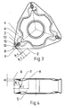
- FIGS. 1 to 4 show a cutting insert according to the invention for copying.
- the cutting insert has a substantially hexagonal shape with three acute angled and three obtuse angled corners on each side.
- the acute-angled corners are each designed as cutting corners -1-, so that by turning and turning the cutting insert in the insert seat of a turning tool a total of six cutting corners -1- can be used.
- Each cutting edge -1- is formed by two, seen in plan view of Figure 3, just together running cutting edges -2-, which are interconnected by a circular section -3-.
- the imaginary extensions of the straight cutting edges -2- intersect at the theoretical intersection -8-.
- each cutting edge -2- in the plane of the associated flank -5- extends from a certain initial level which is directly at the intersection -12- of the bisector -6- of the corresponding cutting edge -1-. with the circular section -3-, first as a composite curve with straight and curved sections sloping down to a lowest point -7-.
- This lowest point -7- is in a very defined distance A 1 from the theoretical intersection -8- of the cutting edges -2- which is dependent on the size of the radius R of the circular section -3-. In the cutting insert illustrated, the distance A 1 is approximately 1.8 times the radius R.
- each cutting edge -2- ascends with the same curve shape up to a point -9- which is at the same height as the initial level of the cutting edge -2- is. Also this point -9- lies in a defined distance A 2 from the theoretical point of intersection -8- Cutting edges -2- corresponds in the concrete case about 3.6 times the radius R of the circular section -3-. From this point -9- each cutting edge -2- runs horizontally.
- the lowest point -7- the trough-shaped depression has a height difference H to the initial level, which corresponds to about 0.3 times the radius R of the circular section -3-.
- the bisector -6- runs at a distance A 4 from the intersection -12- the bisector -6- with the circular section -3- a respect to the surrounding rake face portions recessed rake surface area -15-.
- the distance A 4 corresponds to approximately 0.2 times the radius R of the circular section -3-.
- the clamping surface -4- immediately adjoining the cutting edges -2- initially runs downwards, as seen perpendicularly to the respective cutting edge sections, and then merges into an area which rises up to a central planar surface -14-.
- the central planar surface -14- is made slightly higher than the highest point of the cutting edges -2-, so that a secure support of the cutting insert is ensured in the insert seat of the tool holder.
- each cutting corner -1- intersects the rake face -4- such that a relation to the adjacent rake face portions raised, slightly rounded intersection -11- is formed.
- This can be seen from the detailed view of the cutting edge -1- in Figure 2.
- a surface elevation 13 is provided relative to the adjacent rake face sections, which extends into the rising region of the rake face 4.
- the beginning of the planar elevation -13- has a distance A 3 from the intersection -12- of the bisector -6- with the circular section - 3-, which corresponds to about 0.5 times the radius R.
- the level of increase -13- is substantially above the lowest point -7- of the trough-shaped depression.
Landscapes
- Engineering & Computer Science (AREA)
- Mechanical Engineering (AREA)
- Cutting Tools, Boring Holders, And Turrets (AREA)
Priority Applications (1)
| Application Number | Priority Date | Filing Date | Title |
|---|---|---|---|
| PL07008590T PL1852200T3 (pl) | 2006-05-03 | 2007-04-27 | Wkładka skrawająca do obróbki skrawaniem |
Applications Claiming Priority (1)
| Application Number | Priority Date | Filing Date | Title |
|---|---|---|---|
| AT0036006U AT9432U1 (de) | 2006-05-03 | 2006-05-03 | Schneideinsatz zur spanabhebenden bearbeitung |
Publications (3)
| Publication Number | Publication Date |
|---|---|
| EP1852200A2 true EP1852200A2 (fr) | 2007-11-07 |
| EP1852200A3 EP1852200A3 (fr) | 2009-09-02 |
| EP1852200B1 EP1852200B1 (fr) | 2011-11-02 |
Family
ID=38328741
Family Applications (1)
| Application Number | Title | Priority Date | Filing Date |
|---|---|---|---|
| EP07008590A Not-in-force EP1852200B1 (fr) | 2006-05-03 | 2007-04-27 | Plaquette de coupe pour usinage par enlèvement de copeaux |
Country Status (3)
| Country | Link |
|---|---|
| EP (1) | EP1852200B1 (fr) |
| AT (1) | AT9432U1 (fr) |
| PL (1) | PL1852200T3 (fr) |
Cited By (10)
| Publication number | Priority date | Publication date | Assignee | Title |
|---|---|---|---|---|
| US20150078844A1 (en) * | 2013-09-16 | 2015-03-19 | Iscar, Ltd. | Finish Depth Turning Insert Comprising A Chip Control Arrangement |
| WO2015037447A1 (fr) * | 2013-09-12 | 2015-03-19 | 住友電工ハードメタル株式会社 | Plaquette de coupe |
| US20150090080A1 (en) * | 2012-02-29 | 2015-04-02 | Kyocera Corporation | Cutting insert, cutting tool, and method of manufacturing machined product |
| US20150336175A1 (en) * | 2014-05-20 | 2015-11-26 | Iscar, Ltd. | Cutting insert with chip-control arrangement |
| CN110238417A (zh) * | 2019-06-18 | 2019-09-17 | 郑州煤矿机械集团股份有限公司 | 适于大型结构件的镗孔机夹可转位刀具 |
| JP2019206053A (ja) * | 2018-05-29 | 2019-12-05 | 株式会社タンガロイ | 切削インサート |
| US10710167B2 (en) | 2017-08-02 | 2020-07-14 | Iscar, Ltd. | Negative finish turning insert with chip forming arrangement |
| EP3741483A1 (fr) * | 2019-01-18 | 2020-11-25 | Diametal A.G. | Plaquette de coupe, porte-plaquette et dispositif de coupe |
| JPWO2019235084A1 (ja) * | 2018-06-08 | 2021-03-11 | 株式会社Moldino | 切削インサートおよび刃先交換式切削工具 |
| CN115430852A (zh) * | 2022-10-19 | 2022-12-06 | 株洲钻石切削刀具股份有限公司 | 一种可转位螺纹加工刀片 |
Family Cites Families (4)
| Publication number | Priority date | Publication date | Assignee | Title |
|---|---|---|---|---|
| US5230591A (en) * | 1992-08-10 | 1993-07-27 | Gte Valenite Corporation | Insert for light feed, light depth of cut |
| IL109054A (en) * | 1994-03-21 | 1998-07-15 | Iscar Ltd | Cutting insert |
| US5456557A (en) * | 1994-08-09 | 1995-10-10 | Valenite Inc. | Cutting insert |
| WO1996015869A1 (fr) * | 1994-11-19 | 1996-05-30 | Komet Präzisionswerkzeuge Robert Breuning Gmbh | Plaquette de coupe pour usinage de pieces par enlevement de copeaux |
-
2006
- 2006-05-03 AT AT0036006U patent/AT9432U1/de not_active IP Right Cessation
-
2007
- 2007-04-27 PL PL07008590T patent/PL1852200T3/pl unknown
- 2007-04-27 EP EP07008590A patent/EP1852200B1/fr not_active Not-in-force
Non-Patent Citations (1)
| Title |
|---|
| None |
Cited By (15)
| Publication number | Priority date | Publication date | Assignee | Title |
|---|---|---|---|---|
| US10220448B2 (en) * | 2012-02-29 | 2019-03-05 | Kyocera Corporation | Cutting insert, cutting tool, and method of manufacturing machined product |
| US20150090080A1 (en) * | 2012-02-29 | 2015-04-02 | Kyocera Corporation | Cutting insert, cutting tool, and method of manufacturing machined product |
| WO2015037447A1 (fr) * | 2013-09-12 | 2015-03-19 | 住友電工ハードメタル株式会社 | Plaquette de coupe |
| US20150078844A1 (en) * | 2013-09-16 | 2015-03-19 | Iscar, Ltd. | Finish Depth Turning Insert Comprising A Chip Control Arrangement |
| US9409237B2 (en) * | 2013-09-16 | 2016-08-09 | Iscar, Ltd. | Finish depth turning insert comprising a chip control arrangement |
| US20150336175A1 (en) * | 2014-05-20 | 2015-11-26 | Iscar, Ltd. | Cutting insert with chip-control arrangement |
| US10076788B2 (en) * | 2014-05-20 | 2018-09-18 | Iscar, Ltd. | Cutting insert with chip-control arrangement |
| US10710167B2 (en) | 2017-08-02 | 2020-07-14 | Iscar, Ltd. | Negative finish turning insert with chip forming arrangement |
| JP2019206053A (ja) * | 2018-05-29 | 2019-12-05 | 株式会社タンガロイ | 切削インサート |
| JPWO2019235084A1 (ja) * | 2018-06-08 | 2021-03-11 | 株式会社Moldino | 切削インサートおよび刃先交換式切削工具 |
| US11945034B2 (en) | 2018-06-08 | 2024-04-02 | Moldino Tool Engineering, Ltd. | Cutting insert and cutting edge replacement type cutting tool |
| EP3741483A1 (fr) * | 2019-01-18 | 2020-11-25 | Diametal A.G. | Plaquette de coupe, porte-plaquette et dispositif de coupe |
| US11396049B2 (en) | 2019-01-18 | 2022-07-26 | Diametal A.G. | Turning tool |
| CN110238417A (zh) * | 2019-06-18 | 2019-09-17 | 郑州煤矿机械集团股份有限公司 | 适于大型结构件的镗孔机夹可转位刀具 |
| CN115430852A (zh) * | 2022-10-19 | 2022-12-06 | 株洲钻石切削刀具股份有限公司 | 一种可转位螺纹加工刀片 |
Also Published As
| Publication number | Publication date |
|---|---|
| PL1852200T3 (pl) | 2012-03-30 |
| AT9432U1 (de) | 2007-10-15 |
| EP1852200B1 (fr) | 2011-11-02 |
| EP1852200A3 (fr) | 2009-09-02 |
Similar Documents
| Publication | Publication Date | Title |
|---|---|---|
| EP1852200B1 (fr) | Plaquette de coupe pour usinage par enlèvement de copeaux | |
| DE60002186T2 (de) | Schneideinsatz | |
| DE69409364T2 (de) | Schneideinsatz mit spiralförmiger erhabener fläche und angrenzender ausnehmung | |
| DE10134636B4 (de) | Schneideinsatz mit radial ausgerichteten Spanbildungsnuten | |
| DE60300117T2 (de) | Schneideinsatz zum Schlitzen und Profilieren | |
| DE69312603T2 (de) | Schneideinsatz für einen Fräser | |
| DE60113369T2 (de) | Schneidwerkzeug | |
| DE69936178T2 (de) | Ein Schneideinsatz mit einem Spanformer | |
| EP0758279B1 (fr) | Outil d'usinage | |
| DE60204559T2 (de) | Bohreinsatzgeometrie mit spanspaltender kerbe | |
| EP1087853B1 (fr) | Plaquette de coupe, outil de coupe et procede d'usinage par enlevement de matiere, notamment de surfaces de pieces a symetrie de revolution | |
| EP1213081B2 (fr) | Outil pour usinage de précision par enlèvement de copeaux | |
| DE2338726B2 (de) | Schneideinsatz | |
| EP1294515A1 (fr) | Meche pour un foret helicoidal et procede pour la production d'une goujure dans la zone d'une meche pour un foret helicoidal | |
| AT11676U1 (de) | Schneideinsatz für ein schneidwerkzeug | |
| DE102006023740A1 (de) | Schneideinsatz und Werkzeug, bestehend aus Werkzeughalter und Schneideinsatz | |
| EP1855827A1 (fr) | Plaquette amovible | |
| DE10235606A1 (de) | Vollbohrer für Werkzeugmaschinen | |
| DE112014006093T5 (de) | Einsatz, Werkzeughalter und Aufbau davon | |
| WO2001078926A1 (fr) | Outil de coupe rapporte | |
| EP0787049A1 (fr) | Plaquette de coupe polygonale | |
| EP2683510B1 (fr) | Insert de coupe | |
| DE8325146U1 (de) | Spanbrecheinsatz für Metallschneidwerkzeuge | |
| EP1224992B1 (fr) | Outil de coupe et plaquette amovible | |
| EP0673701A1 (fr) | Alésoir |
Legal Events
| Date | Code | Title | Description |
|---|---|---|---|
| PUAI | Public reference made under article 153(3) epc to a published international application that has entered the european phase |
Free format text: ORIGINAL CODE: 0009012 |
|
| AK | Designated contracting states |
Kind code of ref document: A2 Designated state(s): AT BE BG CH CY CZ DE DK EE ES FI FR GB GR HU IE IS IT LI LT LU LV MC MT NL PL PT RO SE SI SK TR |
|
| AX | Request for extension of the european patent |
Extension state: AL BA HR MK YU |
|
| PUAL | Search report despatched |
Free format text: ORIGINAL CODE: 0009013 |
|
| AK | Designated contracting states |
Kind code of ref document: A3 Designated state(s): AT BE BG CH CY CZ DE DK EE ES FI FR GB GR HU IE IS IT LI LT LU LV MC MT NL PL PT RO SE SI SK TR |
|
| AX | Request for extension of the european patent |
Extension state: AL BA HR MK RS |
|
| 17P | Request for examination filed |
Effective date: 20090917 |
|
| 17Q | First examination report despatched |
Effective date: 20091016 |
|
| AKX | Designation fees paid |
Designated state(s): AT BE BG CH CY CZ DE DK EE ES FI FR GB GR HU IE IS IT LI LT LU LV MC MT NL PL PT RO SE SI SK TR |
|
| GRAP | Despatch of communication of intention to grant a patent |
Free format text: ORIGINAL CODE: EPIDOSNIGR1 |
|
| GRAS | Grant fee paid |
Free format text: ORIGINAL CODE: EPIDOSNIGR3 |
|
| GRAA | (expected) grant |
Free format text: ORIGINAL CODE: 0009210 |
|
| AK | Designated contracting states |
Kind code of ref document: B1 Designated state(s): AT BE BG CH CY CZ DE DK EE ES FI FR GB GR HU IE IS IT LI LT LU LV MC MT NL PL PT RO SE SI SK TR |
|
| REG | Reference to a national code |
Ref country code: GB Ref legal event code: FG4D Free format text: NOT ENGLISH |
|
| REG | Reference to a national code |
Ref country code: CH Ref legal event code: EP |
|
| REG | Reference to a national code |
Ref country code: IE Ref legal event code: FG4D |
|
| REG | Reference to a national code |
Ref country code: DE Ref legal event code: R096 Ref document number: 502007008566 Country of ref document: DE Effective date: 20120202 |
|
| REG | Reference to a national code |
Ref country code: NL Ref legal event code: VDEP Effective date: 20111102 |
|
| REG | Reference to a national code |
Ref country code: SE Ref legal event code: TRGR |
|
| REG | Reference to a national code |
Ref country code: PL Ref legal event code: T3 |
|
| LTIE | Lt: invalidation of european patent or patent extension |
Effective date: 20111102 |
|
| PG25 | Lapsed in a contracting state [announced via postgrant information from national office to epo] |
Ref country code: IS Free format text: LAPSE BECAUSE OF FAILURE TO SUBMIT A TRANSLATION OF THE DESCRIPTION OR TO PAY THE FEE WITHIN THE PRESCRIBED TIME-LIMIT Effective date: 20120302 Ref country code: LT Free format text: LAPSE BECAUSE OF FAILURE TO SUBMIT A TRANSLATION OF THE DESCRIPTION OR TO PAY THE FEE WITHIN THE PRESCRIBED TIME-LIMIT Effective date: 20111102 |
|
| PG25 | Lapsed in a contracting state [announced via postgrant information from national office to epo] |
Ref country code: SI Free format text: LAPSE BECAUSE OF FAILURE TO SUBMIT A TRANSLATION OF THE DESCRIPTION OR TO PAY THE FEE WITHIN THE PRESCRIBED TIME-LIMIT Effective date: 20111102 Ref country code: GR Free format text: LAPSE BECAUSE OF FAILURE TO SUBMIT A TRANSLATION OF THE DESCRIPTION OR TO PAY THE FEE WITHIN THE PRESCRIBED TIME-LIMIT Effective date: 20120203 Ref country code: PT Free format text: LAPSE BECAUSE OF FAILURE TO SUBMIT A TRANSLATION OF THE DESCRIPTION OR TO PAY THE FEE WITHIN THE PRESCRIBED TIME-LIMIT Effective date: 20120302 Ref country code: NL Free format text: LAPSE BECAUSE OF FAILURE TO SUBMIT A TRANSLATION OF THE DESCRIPTION OR TO PAY THE FEE WITHIN THE PRESCRIBED TIME-LIMIT Effective date: 20111102 Ref country code: LV Free format text: LAPSE BECAUSE OF FAILURE TO SUBMIT A TRANSLATION OF THE DESCRIPTION OR TO PAY THE FEE WITHIN THE PRESCRIBED TIME-LIMIT Effective date: 20111102 |
|
| REG | Reference to a national code |
Ref country code: IE Ref legal event code: FD4D |
|
| PG25 | Lapsed in a contracting state [announced via postgrant information from national office to epo] |
Ref country code: CY Free format text: LAPSE BECAUSE OF FAILURE TO SUBMIT A TRANSLATION OF THE DESCRIPTION OR TO PAY THE FEE WITHIN THE PRESCRIBED TIME-LIMIT Effective date: 20111102 |
|
| PG25 | Lapsed in a contracting state [announced via postgrant information from national office to epo] |
Ref country code: EE Free format text: LAPSE BECAUSE OF FAILURE TO SUBMIT A TRANSLATION OF THE DESCRIPTION OR TO PAY THE FEE WITHIN THE PRESCRIBED TIME-LIMIT Effective date: 20111102 Ref country code: BG Free format text: LAPSE BECAUSE OF FAILURE TO SUBMIT A TRANSLATION OF THE DESCRIPTION OR TO PAY THE FEE WITHIN THE PRESCRIBED TIME-LIMIT Effective date: 20120202 Ref country code: DK Free format text: LAPSE BECAUSE OF FAILURE TO SUBMIT A TRANSLATION OF THE DESCRIPTION OR TO PAY THE FEE WITHIN THE PRESCRIBED TIME-LIMIT Effective date: 20111102 Ref country code: SK Free format text: LAPSE BECAUSE OF FAILURE TO SUBMIT A TRANSLATION OF THE DESCRIPTION OR TO PAY THE FEE WITHIN THE PRESCRIBED TIME-LIMIT Effective date: 20111102 Ref country code: IE Free format text: LAPSE BECAUSE OF FAILURE TO SUBMIT A TRANSLATION OF THE DESCRIPTION OR TO PAY THE FEE WITHIN THE PRESCRIBED TIME-LIMIT Effective date: 20111102 |
|
| PGFP | Annual fee paid to national office [announced via postgrant information from national office to epo] |
Ref country code: DE Payment date: 20120420 Year of fee payment: 6 Ref country code: CZ Payment date: 20120420 Year of fee payment: 6 |
|
| PG25 | Lapsed in a contracting state [announced via postgrant information from national office to epo] |
Ref country code: RO Free format text: LAPSE BECAUSE OF FAILURE TO SUBMIT A TRANSLATION OF THE DESCRIPTION OR TO PAY THE FEE WITHIN THE PRESCRIBED TIME-LIMIT Effective date: 20111102 |
|
| PGFP | Annual fee paid to national office [announced via postgrant information from national office to epo] |
Ref country code: FR Payment date: 20120507 Year of fee payment: 6 Ref country code: GB Payment date: 20120419 Year of fee payment: 6 Ref country code: PL Payment date: 20120330 Year of fee payment: 6 Ref country code: SE Payment date: 20120418 Year of fee payment: 6 |
|
| PLBE | No opposition filed within time limit |
Free format text: ORIGINAL CODE: 0009261 |
|
| STAA | Information on the status of an ep patent application or granted ep patent |
Free format text: STATUS: NO OPPOSITION FILED WITHIN TIME LIMIT |
|
| PGFP | Annual fee paid to national office [announced via postgrant information from national office to epo] |
Ref country code: IT Payment date: 20120420 Year of fee payment: 6 |
|
| 26N | No opposition filed |
Effective date: 20120803 |
|
| BERE | Be: lapsed |
Owner name: CERATIZIT AUSTRIA -G. M.B.H. Effective date: 20120430 |
|
| REG | Reference to a national code |
Ref country code: DE Ref legal event code: R097 Ref document number: 502007008566 Country of ref document: DE Effective date: 20120803 |
|
| PG25 | Lapsed in a contracting state [announced via postgrant information from national office to epo] |
Ref country code: MC Free format text: LAPSE BECAUSE OF NON-PAYMENT OF DUE FEES Effective date: 20120430 |
|
| REG | Reference to a national code |
Ref country code: CH Ref legal event code: PL |
|
| PG25 | Lapsed in a contracting state [announced via postgrant information from national office to epo] |
Ref country code: BE Free format text: LAPSE BECAUSE OF NON-PAYMENT OF DUE FEES Effective date: 20120430 Ref country code: LI Free format text: LAPSE BECAUSE OF NON-PAYMENT OF DUE FEES Effective date: 20120430 Ref country code: CH Free format text: LAPSE BECAUSE OF NON-PAYMENT OF DUE FEES Effective date: 20120430 |
|
| PGFP | Annual fee paid to national office [announced via postgrant information from national office to epo] |
Ref country code: AT Payment date: 20120411 Year of fee payment: 6 |
|
| PG25 | Lapsed in a contracting state [announced via postgrant information from national office to epo] |
Ref country code: ES Free format text: LAPSE BECAUSE OF FAILURE TO SUBMIT A TRANSLATION OF THE DESCRIPTION OR TO PAY THE FEE WITHIN THE PRESCRIBED TIME-LIMIT Effective date: 20120213 |
|
| PG25 | Lapsed in a contracting state [announced via postgrant information from national office to epo] |
Ref country code: FI Free format text: LAPSE BECAUSE OF FAILURE TO SUBMIT A TRANSLATION OF THE DESCRIPTION OR TO PAY THE FEE WITHIN THE PRESCRIBED TIME-LIMIT Effective date: 20111102 |
|
| PG25 | Lapsed in a contracting state [announced via postgrant information from national office to epo] |
Ref country code: MT Free format text: LAPSE BECAUSE OF FAILURE TO SUBMIT A TRANSLATION OF THE DESCRIPTION OR TO PAY THE FEE WITHIN THE PRESCRIBED TIME-LIMIT Effective date: 20111102 |
|
| REG | Reference to a national code |
Ref country code: SE Ref legal event code: EUG |
|
| REG | Reference to a national code |
Ref country code: AT Ref legal event code: MM01 Ref document number: 531469 Country of ref document: AT Kind code of ref document: T Effective date: 20130430 |
|
| GBPC | Gb: european patent ceased through non-payment of renewal fee |
Effective date: 20130427 |
|
| PG25 | Lapsed in a contracting state [announced via postgrant information from national office to epo] |
Ref country code: AT Free format text: LAPSE BECAUSE OF NON-PAYMENT OF DUE FEES Effective date: 20130430 Ref country code: CZ Free format text: LAPSE BECAUSE OF NON-PAYMENT OF DUE FEES Effective date: 20130427 Ref country code: GB Free format text: LAPSE BECAUSE OF NON-PAYMENT OF DUE FEES Effective date: 20130427 Ref country code: DE Free format text: LAPSE BECAUSE OF NON-PAYMENT OF DUE FEES Effective date: 20131101 Ref country code: SE Free format text: LAPSE BECAUSE OF NON-PAYMENT OF DUE FEES Effective date: 20130428 |
|
| REG | Reference to a national code |
Ref country code: FR Ref legal event code: ST Effective date: 20131231 |
|
| REG | Reference to a national code |
Ref country code: DE Ref legal event code: R119 Ref document number: 502007008566 Country of ref document: DE Effective date: 20131101 |
|
| PG25 | Lapsed in a contracting state [announced via postgrant information from national office to epo] |
Ref country code: FR Free format text: LAPSE BECAUSE OF NON-PAYMENT OF DUE FEES Effective date: 20130430 Ref country code: IT Free format text: LAPSE BECAUSE OF NON-PAYMENT OF DUE FEES Effective date: 20130427 |
|
| PG25 | Lapsed in a contracting state [announced via postgrant information from national office to epo] |
Ref country code: TR Free format text: LAPSE BECAUSE OF FAILURE TO SUBMIT A TRANSLATION OF THE DESCRIPTION OR TO PAY THE FEE WITHIN THE PRESCRIBED TIME-LIMIT Effective date: 20111102 |
|
| PG25 | Lapsed in a contracting state [announced via postgrant information from national office to epo] |
Ref country code: LU Free format text: LAPSE BECAUSE OF NON-PAYMENT OF DUE FEES Effective date: 20120427 |
|
| PG25 | Lapsed in a contracting state [announced via postgrant information from national office to epo] |
Ref country code: HU Free format text: LAPSE BECAUSE OF FAILURE TO SUBMIT A TRANSLATION OF THE DESCRIPTION OR TO PAY THE FEE WITHIN THE PRESCRIBED TIME-LIMIT Effective date: 20070427 |
|
| REG | Reference to a national code |
Ref country code: PL Ref legal event code: LAPE |
|
| PG25 | Lapsed in a contracting state [announced via postgrant information from national office to epo] |
Ref country code: PL Free format text: LAPSE BECAUSE OF NON-PAYMENT OF DUE FEES Effective date: 20130427 |