EP1852341A2 - Protège-main pour un guidon de bicyclette ou de moto - Google Patents
Protège-main pour un guidon de bicyclette ou de moto Download PDFInfo
- Publication number
- EP1852341A2 EP1852341A2 EP07251857A EP07251857A EP1852341A2 EP 1852341 A2 EP1852341 A2 EP 1852341A2 EP 07251857 A EP07251857 A EP 07251857A EP 07251857 A EP07251857 A EP 07251857A EP 1852341 A2 EP1852341 A2 EP 1852341A2
- Authority
- EP
- European Patent Office
- Prior art keywords
- arm
- shield
- handguard
- assembly
- vehicle
- Prior art date
- Legal status (The legal status is an assumption and is not a legal conclusion. Google has not performed a legal analysis and makes no representation as to the accuracy of the status listed.)
- Withdrawn
Links
Images


Classifications
-
- B—PERFORMING OPERATIONS; TRANSPORTING
- B62—LAND VEHICLES FOR TRAVELLING OTHERWISE THAN ON RAILS
- B62J—CYCLE SADDLES OR SEATS; AUXILIARY DEVICES OR ACCESSORIES SPECIALLY ADAPTED TO CYCLES AND NOT OTHERWISE PROVIDED FOR, e.g. ARTICLE CARRIERS OR CYCLE PROTECTORS
- B62J23/00—Other protectors specially adapted for cycles
-
- Y—GENERAL TAGGING OF NEW TECHNOLOGICAL DEVELOPMENTS; GENERAL TAGGING OF CROSS-SECTIONAL TECHNOLOGIES SPANNING OVER SEVERAL SECTIONS OF THE IPC; TECHNICAL SUBJECTS COVERED BY FORMER USPC CROSS-REFERENCE ART COLLECTIONS [XRACs] AND DIGESTS
- Y10—TECHNICAL SUBJECTS COVERED BY FORMER USPC
- Y10T—TECHNICAL SUBJECTS COVERED BY FORMER US CLASSIFICATION
- Y10T74/00—Machine element or mechanism
- Y10T74/20—Control lever and linkage systems
- Y10T74/20576—Elements
- Y10T74/20732—Handles
- Y10T74/2078—Handle bars
- Y10T74/20822—Attachments and accessories
-
- Y—GENERAL TAGGING OF NEW TECHNOLOGICAL DEVELOPMENTS; GENERAL TAGGING OF CROSS-SECTIONAL TECHNOLOGIES SPANNING OVER SEVERAL SECTIONS OF THE IPC; TECHNICAL SUBJECTS COVERED BY FORMER USPC CROSS-REFERENCE ART COLLECTIONS [XRACs] AND DIGESTS
- Y10—TECHNICAL SUBJECTS COVERED BY FORMER USPC
- Y10T—TECHNICAL SUBJECTS COVERED BY FORMER US CLASSIFICATION
- Y10T74/00—Machine element or mechanism
- Y10T74/20—Control lever and linkage systems
- Y10T74/20576—Elements
- Y10T74/20732—Handles
- Y10T74/2078—Handle bars
- Y10T74/20828—Handholds and grips
Definitions
- the present application relates to a handguard for a handlebar.
- the present application relates to a pivotal handguard for a handlebar of a vehicle, such as a motorbike, motorcycle, motor scooter, bicycle, or all-terrain vehicle (“ATV").
- ATV all-terrain vehicle
- Handguards for protecting the hands of riders of motorbikes, motorcycles, motor scooters, bicycles, and ATVs are known in the art.
- the handguard is configured to protect a rider's hands from debris as well as wind and rain.
- the handguard includes a shield member having a first end and a second end, wherein each end is rigidly connected to a handlebar of a vehicle.
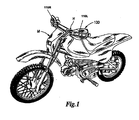
- Figure 1 is a perspective view of one embodiment of a handguard assembly mounted on a motorcycle:
- Figure 2 is a top elevation view of one embodiment a handguard assembly mounted on a handlebar;
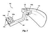
- Figure 3 is a perspective view of one embodiment of a handguard assembly
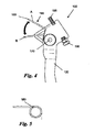
- Figure 4 is a top elevation view of a portion of one embodiment of a handguard assembly
- Figure 5 is a top view of a torsion spring for a handguard assembly
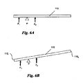
- Figures 6A-C are simplified force diagrams illustrating exemplary forces applied to a shield of one embodiment of a handguard assembly.
- Figure 7 is a simplified force diagram illustrating an external force applied to a shield of one embodiment of a handguard assembly.
- Light and “left” as used herein refer to the right and left directions as viewed from the perspective of a rider of the vehicle.
- An “inner” direction as used herein refers to a direction towards the body of the vehicle.
- An “outer” direction as used herein refers to a direction away from the body of the vehicle.
- Figure 1 illustrates a simplified perspective view of one embodiment of a handguard assembly 100, including left and right handshields 110L,R mounted on a handlebar H of a motorbike M.
- the handguard assembly 100 is positioned in front of the handlebar H to protect a rider's hand.
- the handguard assembly 100 may be employed on a motorcycle, motor scooter, bicycle, ATV, or any other vehicle having handlebars.
- the shields 110L,R are constructed of a polymeric material.
- exemplary polymeric materials include, without limitation, polypropylene, polyethylene, ethylene propylene diene monomer (EPDM) elastomeric, or a combination thereof.
- EPDM ethylene propylene diene monomer
- Polypropylene provides stiffness to the shields while polyethylene provides resilience and EPDM elastomeric provides flexibility.
- the shields are constructed of metal.
- each shield 110L,R is constructed of a polymeric material, it can be molded to include complex features and to facilitate installation on a handlebar H. Furthermore, the use of a polymeric material allows each shield 110L,R to absorb impacts and retain its shape.
- Figure 2 illustrates a top view of one embodiment of the handguard assembly 100 connected to the handlebar H.
- the shield 110 is connected to the handlebar H via an arm 120.
- the shield 110 is configured to move from a first position 110a to a second position 110b.
- the shield 110 is placed in the first position 110a under normal conditions and is moved to the second position 110b when an external force is applied to an outer portion of the shield 110.
- the shield 110 moves by pivoting about a pivot point P.
- the shield translates by sliding from a first position to a second position.
- the shield is configured to both pivot and translate.
- Figure 3 illustrates a perspective view of one embodiment of a handguard assembly 100.
- the handguard assembly 100 includes the shield 110 and arm 120, and further includes a mount 130.
- the arm 120 and/or the mount 130 is constructed of aluminum.
- at least one of the arm 120 and mount 130 is constructed of steel, iron, or any other known metal or alloy.
- at least one of the arm 120 and mount 130 is constructed of a polymeric material.
- the arm 120 and the mount 130 may be constructed of the same material or of different material.
- the mount 130 is a separate component connected to the arm 120.
- the mount 130 is configured to be connected to either the handlebar (not shown) or perch (not shown) of a vehicle.
- the mount 130 includes first and second C-shaped portions 140a,b.
- the mount may be a unitary O-shaped member or a pair of pivotally connected members.
- the mount 130 is pivotally connected to the arm 120 via a pin or shaft (not shown). The mount 130 is then locked into position by a set screw, a locking pin, a locking washer, or other known locking mechanism.
- the mount 130 is pivotally connected to the arm 120 via a bolt or screw (not shown).
- the mount 130 is fixedly connected to the arm 120 via one or more bolts, screws, pins, nails, ties, or adhesive.
- the mount is an extension of a unitary arm member.
- the C-shaped portions 140a,b are configured to be connected to each other via one or more bolts 150.
- the C-shaped portions may be connected by screws, ties, or any other appropriate connecting members.
- the C-shaped portions 140a,b of mount 130 are disposed in an upright configuration.
- the C-shaped portions are disposed horizontally.
- the C-shaped portions may be disposed in any orientation.
- the arm 120 is pivotally connected to the shield 110.
- the shield 110 includes a top projection 160a and a bottom projection 160b.
- the arm 120 is configured to be received between the top and bottom projections 160a,b.
- the shield includes a single projection and the arm includes a top and bottom projection.
- the shield includes a single projection and the arm is disposed above or below the projection.
- the arm is slidably connected to the shield.
- the arm is both pivotally and slidably connected to the shield.
- the top projection 160a and the bottom projection 160b of the shield 110 include aligned apertures configured to receive a pin 170 in a generally vertical orientation.
- the arm 120 includes a corresponding aligned aperture configured to receive the pin 170 such that the arm is pivotally connected to the shield 110.
- the arm 120 and shield 130 are configured to receive a shaft or other known pivoting members.
- the pin 170 is configured to receive a locking mechanism (not shown) to hold the pin 170 in place and maintain the pivotal connection.
- exemplary locking mechanisms include ties, pins, locking washers, or threaded nuts.
- the arm includes a pair of projections configured to be received in the apertures of the first and second projections of the shield.
- the apertures of the first and second projections of the shield are elongated, thus allowing translational movement between the arm and the shield.
- the arm includes an elongated aperture configured to receive a pin, thus allowing translational movement between the arm and the shield.
- Figure 4 illustrates a top elevation view of one embodiment of a portion of the arm 120 of the handguard assembly 100.
- the arm 120 is connected to a torsion spring 180.
- a detailed view of an exemplary torsion spring is further illustrated in Figure 5.
- the arm may be connected to a spring, a elastomeric member, a piston and cylinder assembly, or any other known biasing member.
- the torsion spring 180 is disposed about the pin 170.
- a first end (not shown) of the torsion spring 180 abuts a portion of the arm 120.
- a second end 185 of the torsion spring 180 extends away from the arm 120 to contact the shield (not shown).
- the torsion spring 180 thus biases the shield in a clockwise direction about the pin 170.
- the second end 185 of the torsion spring 180 is configured to be moved from a first position A to a plurality of other positions, including second position B.
- the torsion spring 180 is in stable equilibrium in the first position A. In other words, a force must be applied to the torsion spring 180 to move its second end 185 from the first position A towards the second position B. When the force is removed, the second end 185 automatically returns to the first position A.
- the arm includes a latch, a notch, or other such retaining mechanism to hold the second end 185 of the torsion spring 180 in place at the second position B. In this embodiment, a second force must be applied to the torsion spring 180 to move the second end 185 from the second position B to the first position A.
- the torsion spring 180 is in stable equilibrium in the second position B and the arm includes a latch, a notch, or other such retaining mechanism to hold the second end 185 of the torsion spring 180 in place at the first position A.
- a force must be applied to the torsion spring 180 to move its second end 185 from the first position A towards the second position B.
- a second force must be applied to the torsion spring 180 to move its second end 185 from the second position B towards the first position A.
- the arm also includes a set screw 190 configured to abut the shield (not shown) and place the shield in a selected orientation relative to the handlebar (not shown).
- the arm may include a ratcheted member or other known adjustment members.
- the end 195 of the set screw 190 extends away from the arm to contact the shield 110 (not shown).
- FIGS. 6A-6C are simplified force diagrams illustrating the forces acting on the shield 110.
- the first force exerted by the torsion spring 180 is illustrated as F 1 and the second force exerted by the set screw 190 is illustrated as F 2 .
- the pin 170 of Figure 4 is shown as pivot point P.
- Figure 6A illustrates a setting where the set screw 190 is adjusted to position the shield 110 generally parallel to the handlebar (not shown).
- Figure 6B illustrates a setting where the set screw 190 is adjusted to position an inner portion 110 1 of the shield 110 closer to the handlebar (not shown) than an outer portion 110 o .
- Figure 6C illustrates a setting where the set screw 190 is adjusted to position the outer portion 110 o of the shield 110 closer to the handlebar (not shown) than the inner portion 110 i .
- Figure 7 is a simplified force diagram illustrating an external force F E applied to the outer portion 110 o of the shield 110, wherein the external force F E has a greater moment than the second force F 2 applied by the set screw 190.
- the outer portion 110 o of the shield 110 will pivot forward such that the set screw 190 no longer contacts the shield 110.
- the shield 110 pivots from a first position 110a to a second position 110b.
- the shield 110 returns to the first position 110a when the external force F E is removed.
- the arm 120 includes a latch, a notch, or another known retaining mechanism (not shown) to keep the shield 110 in the second position 110b after the external force F E is removed.
- the shield 110 returns to the first position 110a when an additional force is applied to the outer portion of the shield 110, in a direction opposite that of the external force F E .
- the external force F E may be applied by various sources. For example, if the vehicle falls down while traveling uphill, the vehicle may slide backwards down the hill. In this instance, the ground applies the external force F E . In another example, if the vehicle collides with an object, the rider may be thrown forward from the vehicle and the rider may strike the outer portion 110 o of the shield 110, thereby applying an external force F E . In yet another example, the outer portion 110 o of the shield 110 may strike an object while the vehicle is traveling in reverse. In another example, debris or other foreign objects may strike the outer portion 110 o of the shield 110 from the rear.
- the shield 110 By pivoting to a second position 110b, the shield 110 absorbs impacts without suffering as much damage as it otherwise would. Further, when the shield 110 pivots, more space is created between the shield 110 and the handlebar H, thereby creating more clearance for a rider to remove his hand from the handlebar H. While the present application has been illustrated by the description of embodiments thereof, and while the embodiments have been described in considerable detail, it is not the intention of the applicants to restrict or in any way limit the scope of the appended claims to such detail. Additional advantages and modifications will readily appear to those skilled in the art. Therefore, the application, in its broader aspects, is not limited to the specific details, the representative apparatus, and illustrative examples shown and described. Accordingly, departures may be made from such details without departing from the spirit or scope of the applicant's general inventive concept.
Landscapes
- Engineering & Computer Science (AREA)
- Mechanical Engineering (AREA)
- Steering Devices For Bicycles And Motorcycles (AREA)
Applications Claiming Priority (1)
| Application Number | Priority Date | Filing Date | Title |
|---|---|---|---|
| US11/416,544 US8534159B2 (en) | 2006-05-03 | 2006-05-03 | Movable handguard assembly |
Publications (2)
| Publication Number | Publication Date |
|---|---|
| EP1852341A2 true EP1852341A2 (fr) | 2007-11-07 |
| EP1852341A3 EP1852341A3 (fr) | 2008-10-15 |
Family
ID=38241581
Family Applications (1)
| Application Number | Title | Priority Date | Filing Date |
|---|---|---|---|
| EP07251857A Withdrawn EP1852341A3 (fr) | 2006-05-03 | 2007-05-03 | Protège-main pour un guidon de bicyclette ou de moto |
Country Status (2)
| Country | Link |
|---|---|
| US (1) | US8534159B2 (fr) |
| EP (1) | EP1852341A3 (fr) |
Cited By (3)
| Publication number | Priority date | Publication date | Assignee | Title |
|---|---|---|---|---|
| DE202010006315U1 (de) | 2010-05-03 | 2011-10-27 | Oliver Werner | Schutzvorrichtung zum Anbringen an einem von einem Bediener zu betätigenden Handgriff |
| ITTV20120174A1 (it) * | 2012-09-11 | 2014-03-12 | Lightech Srl | Dispositivo di protezione |
| WO2016124352A1 (fr) * | 2015-02-06 | 2016-08-11 | Bayerische Motoren Werke Aktiengesellschaft | Protège-main pour véhicule |
Families Citing this family (13)
| Publication number | Priority date | Publication date | Assignee | Title |
|---|---|---|---|---|
| US20080203762A1 (en) * | 2007-02-23 | 2008-08-28 | Randall Shimanski | Handguard apparatus and methods |
| US20120234129A1 (en) * | 2011-03-17 | 2012-09-20 | Andy Adan | Breakaway Hand Guard |
| US20120279348A1 (en) * | 2011-05-04 | 2012-11-08 | Eric Wood | Motorcycle Lever Protection Guard |
| US9669893B2 (en) | 2014-03-07 | 2017-06-06 | Joseph Moos | Hinged handgrip pad |
| US9499225B2 (en) | 2014-07-14 | 2016-11-22 | Takie Adonis Stanger | Flexible hand guard |
| US9802666B2 (en) * | 2014-08-01 | 2017-10-31 | Andrew Serbinski | Multifunctional hand guard |
| US9573647B2 (en) | 2014-08-13 | 2017-02-21 | William T. Ross | Shock-absorbing handguards for handle bars |
| USD776579S1 (en) * | 2015-05-11 | 2017-01-17 | Kawasaki Jukogyo Kabushiki Kaisha | Pair of hand guards for a motorcycle |
| USD813729S1 (en) * | 2015-09-18 | 2018-03-27 | Andrew Serbinski | Vehicle hand guard |
| US10773766B2 (en) * | 2018-05-04 | 2020-09-15 | Takie Adonis Stanger | Omni-directional self-orienting breakaway hand guards |
| JP6821720B2 (ja) | 2019-01-31 | 2021-01-27 | 本田技研工業株式会社 | ナックルガード |
| US11738818B1 (en) * | 2021-12-29 | 2023-08-29 | Stephen Zvorsky | Integrated hand guard and lighting system |
| US12365419B2 (en) * | 2023-12-27 | 2025-07-22 | Kawasaki Motors, Ltd. | Saddle-type vehicle |
Family Cites Families (24)
| Publication number | Priority date | Publication date | Assignee | Title |
|---|---|---|---|---|
| US598546A (en) * | 1898-02-08 | Shade for handles of bicycles | ||
| US1473326A (en) * | 1923-03-29 | 1923-11-06 | Slawienski Mike | Handle attachment for motor cycles |
| GB480985A (en) * | 1936-12-23 | 1938-03-03 | Edward Carey Riggall | Improvements in or relating to hand shields for use on the handlebars of motor-cycles and the like |
| GB636349A (en) * | 1947-06-21 | 1950-04-26 | Bernard Farnell Wade | An improved hand shield for attachment to the handle bars of motor cycles or the like |
| US2571310A (en) * | 1949-05-03 | 1951-10-16 | Walter A Thiem | Can opener |
| US3875819A (en) * | 1973-04-27 | 1975-04-08 | Jacobsen Mfg Co | Safety grip for powered implement |
| US3982446A (en) * | 1975-05-30 | 1976-09-28 | Andrew Van Dyken | Cruise control apparatus for hand grip throttle control |
| US4141567A (en) | 1977-01-31 | 1979-02-27 | Scott Gary M | Handle bar hand guards |
| US4137793A (en) * | 1977-09-09 | 1979-02-06 | Sowell William E | Throttle control device for motorcycles and the like |
| USD319992S (en) | 1989-03-13 | 1991-09-17 | Acerbis Plastica Italia | Pair of mountain bike handguards |
| US4875386A (en) * | 1989-06-05 | 1989-10-24 | Dickerson Daryl E | Handlegrip cruise assist device |
| US5740700A (en) * | 1996-05-17 | 1998-04-21 | Redmond; Steven A. | Handlebar hand cover |
| US5832786A (en) | 1997-06-26 | 1998-11-10 | Risley; Robert | Gold wing hand protector |
| US6752447B2 (en) * | 2000-12-19 | 2004-06-22 | Bombardier Recreational Products Inc. | Windshield assembly for an all terrain vehicle |
| US6505877B1 (en) | 2002-01-15 | 2003-01-14 | John Peter Devlin | Portable two-piece motorcycle windshield |
| US7257873B2 (en) | 2003-01-31 | 2007-08-21 | Laivins Kenneth T | Method for manufacturing hand guards |
| US7644642B2 (en) | 2003-02-14 | 2010-01-12 | Promoto Billet | Handlebar top clamp for steering systems |
| US20040173046A1 (en) | 2003-03-05 | 2004-09-09 | Dennis Hancock | Hand guard |
| US6736441B1 (en) | 2003-03-07 | 2004-05-18 | Harley-Davidson Motor Company Group, Inc. | Detachable windshield for a motorcycle |
| USD492623S1 (en) | 2003-03-21 | 2004-07-06 | Powermadd, Inc. | Handle bar mounted hand guard |
| USD492523S1 (en) * | 2003-06-26 | 2004-07-06 | Masco Corporation Of Indiana | Towel bar post |
| ES2337086T3 (es) * | 2006-07-20 | 2010-04-20 | Sandro Mentasti S.R.L. | Guardamanos para manillar de motocicleta. |
| DE202010006315U1 (de) * | 2010-05-03 | 2011-10-27 | Oliver Werner | Schutzvorrichtung zum Anbringen an einem von einem Bediener zu betätigenden Handgriff |
| US20120234129A1 (en) * | 2011-03-17 | 2012-09-20 | Andy Adan | Breakaway Hand Guard |
-
2006
- 2006-05-03 US US11/416,544 patent/US8534159B2/en not_active Expired - Fee Related
-
2007
- 2007-05-03 EP EP07251857A patent/EP1852341A3/fr not_active Withdrawn
Cited By (6)
| Publication number | Priority date | Publication date | Assignee | Title |
|---|---|---|---|---|
| DE202010006315U1 (de) | 2010-05-03 | 2011-10-27 | Oliver Werner | Schutzvorrichtung zum Anbringen an einem von einem Bediener zu betätigenden Handgriff |
| EP2384960A1 (fr) | 2010-05-03 | 2011-11-09 | Oliver Werner | Système de protection pour l'installation sur une poignée |
| ITTV20120174A1 (it) * | 2012-09-11 | 2014-03-12 | Lightech Srl | Dispositivo di protezione |
| WO2016124352A1 (fr) * | 2015-02-06 | 2016-08-11 | Bayerische Motoren Werke Aktiengesellschaft | Protège-main pour véhicule |
| DE102015202096A1 (de) | 2015-02-06 | 2016-08-11 | Bayerische Motoren Werke Aktiengesellschaft | Handschutzvorrichtung für ein Fahrzeug |
| US10442489B2 (en) | 2015-02-06 | 2019-10-15 | Bayerische Motoren Werke Aktiengesellschaft | Hand protection device for a vehicle |
Also Published As
| Publication number | Publication date |
|---|---|
| US8534159B2 (en) | 2013-09-17 |
| US20070256514A1 (en) | 2007-11-08 |
| EP1852341A3 (fr) | 2008-10-15 |
Similar Documents
| Publication | Publication Date | Title |
|---|---|---|
| EP1852341A2 (fr) | Protège-main pour un guidon de bicyclette ou de moto | |
| US7033294B2 (en) | Bicycle rear derailleur guard | |
| US5727429A (en) | Low profile bicycle pedal and cleat assembly | |
| CN103538687B (zh) | 自行车后拨链器 | |
| US7644642B2 (en) | Handlebar top clamp for steering systems | |
| US5593168A (en) | Bicycle shock absorbing assembly | |
| US7044874B2 (en) | Bicycle rear derailleur | |
| US20220274527A1 (en) | Omni-directional self-orienting breakaway structures | |
| US7104585B2 (en) | Forward disposed part installation structure of motorcycle | |
| US8864094B2 (en) | Fender mount for mirror | |
| US20050212251A1 (en) | Motorcycle fork bottom which is stiffer front-to-back than side-to-side | |
| US5685202A (en) | Bicycle pedal device with two cleat retaining units | |
| CN101357656A (zh) | 机动两轮车的倾覆传感器的设置结构 | |
| US20090189380A1 (en) | Plastic handguard | |
| US7392874B2 (en) | Rear wheel suspension | |
| US10272966B2 (en) | Windscreen safety assembly | |
| CA2452721C (fr) | Retroviseur pour bicyclette | |
| US20040016316A1 (en) | Adjustable extended riser | |
| JP3629567B2 (ja) | スクータ型自動二輪車 | |
| US20090008920A1 (en) | Adjustable rear fender assembly | |
| US20060130606A1 (en) | Handlebar shock absorbing system for bicycles | |
| CN1090119C (zh) | 小型两轮摩托车 | |
| EP2017166B1 (fr) | Véhicule de type à selle | |
| US7775138B2 (en) | Wire fixing structure | |
| KR100990281B1 (ko) | 자전거의 핸들 프레임 회동 장치 |
Legal Events
| Date | Code | Title | Description |
|---|---|---|---|
| PUAI | Public reference made under article 153(3) epc to a published international application that has entered the european phase |
Free format text: ORIGINAL CODE: 0009012 |
|
| AK | Designated contracting states |
Kind code of ref document: A2 Designated state(s): AT BE BG CH CY CZ DE DK EE ES FI FR GB GR HU IE IS IT LI LT LU LV MC MT NL PL PT RO SE SI SK TR |
|
| AX | Request for extension of the european patent |
Extension state: AL BA HR MK YU |
|
| PUAL | Search report despatched |
Free format text: ORIGINAL CODE: 0009013 |
|
| AK | Designated contracting states |
Kind code of ref document: A3 Designated state(s): AT BE BG CH CY CZ DE DK EE ES FI FR GB GR HU IE IS IT LI LT LU LV MC MT NL PL PT RO SE SI SK TR |
|
| AX | Request for extension of the european patent |
Extension state: AL BA HR MK RS |
|
| AKX | Designation fees paid | ||
| REG | Reference to a national code |
Ref country code: DE Ref legal event code: 8566 |
|
| STAA | Information on the status of an ep patent application or granted ep patent |
Free format text: STATUS: THE APPLICATION IS DEEMED TO BE WITHDRAWN |
|
| 18D | Application deemed to be withdrawn |
Effective date: 20090416 |