EP1852368B1 - Dispositif de protection - Google Patents
Dispositif de protection Download PDFInfo
- Publication number
- EP1852368B1 EP1852368B1 EP20070009061 EP07009061A EP1852368B1 EP 1852368 B1 EP1852368 B1 EP 1852368B1 EP 20070009061 EP20070009061 EP 20070009061 EP 07009061 A EP07009061 A EP 07009061A EP 1852368 B1 EP1852368 B1 EP 1852368B1
- Authority
- EP
- European Patent Office
- Prior art keywords
- barrier
- accordance
- protection device
- protection
- initial position
- Prior art date
- Legal status (The legal status is an assumption and is not a legal conclusion. Google has not performed a legal analysis and makes no representation as to the accuracy of the status listed.)
- Not-in-force
Links
- 230000004888 barrier function Effects 0.000 claims description 63
- 239000000463 material Substances 0.000 claims description 6
- 238000013022 venting Methods 0.000 claims description 4
- 230000004913 activation Effects 0.000 claims description 2
- 208000027418 Wounds and injury Diseases 0.000 description 6
- 230000006378 damage Effects 0.000 description 6
- 208000014674 injury Diseases 0.000 description 6
- 239000002699 waste material Substances 0.000 description 3
- 239000002184 metal Substances 0.000 description 2
- 230000009471 action Effects 0.000 description 1
- 230000009286 beneficial effect Effects 0.000 description 1
- 230000008901 benefit Effects 0.000 description 1
- 238000010276 construction Methods 0.000 description 1
- 230000004941 influx Effects 0.000 description 1
- 230000003993 interaction Effects 0.000 description 1
- 230000035515 penetration Effects 0.000 description 1
- 230000035939 shock Effects 0.000 description 1
Images

Classifications
-
- B—PERFORMING OPERATIONS; TRANSPORTING
- B65—CONVEYING; PACKING; STORING; HANDLING THIN OR FILAMENTARY MATERIAL
- B65F—GATHERING OR REMOVAL OF DOMESTIC OR LIKE REFUSE
- B65F3/00—Vehicles particularly adapted for collecting refuse
-
- B—PERFORMING OPERATIONS; TRANSPORTING
- B65—CONVEYING; PACKING; STORING; HANDLING THIN OR FILAMENTARY MATERIAL
- B65F—GATHERING OR REMOVAL OF DOMESTIC OR LIKE REFUSE
- B65F3/00—Vehicles particularly adapted for collecting refuse
- B65F3/001—Vehicles particularly adapted for collecting refuse for segregated refuse collecting, e.g. vehicles with several compartments
Definitions
- the present invention relates to a security device for securing a working area of a refuse container emptying device, with a barrier, which can be moved from a basic position into a securing position.
- Such hedging devices are used in particular in garbage trucks, wherein it should be prevented that when emptying a refuse container in the garbage truck people penetrate into the work area of Müll hereerentleervoriques and injured by this.
- the object of the present invention is therefore to provide a security device for securing a working area of a refuse container emptying device, which has an increased operating safety.
- the barrier which can be moved from a basic position into a securing position, consists of a flexible material. Hits the barrier during their movement from the basic position in the securing position of a person or an object, the barrier can yield due to the flexibility of their material, so that injuries can be avoided. Even in its basic position, the barrier can give way when a person bumps against them, so that here too the risk of injury is reduced and the Müll interchangeerentleervorraum is better to use.
- the barrier according to the invention comprises a hose element. This is a particularly inexpensive and easy way to provide a flexible barrier.
- the barrier is moved by ventilating the hose element from the basic position into the securing position. Because so the movement the barrier is caused only by the influx of air into the hose element, a possible shock of the barrier against a person in their range of motion is very soft, so that injuries are excluded and security is increased.
- the hose member thereby forms a closed chamber, so that after filling the hose member with air, preferably with compressed air, the barrier is relatively stable in its securing position and thus effectively prevents movement of persons in the working area of Müll thuserentleervorides. For venting the hose element this is advantageously connected at one end to a compressed air supply.
- the barrier moves by venting the hose member from the securing position to the basic position.
- the barrier between the basic position and the securing position are reciprocated, which guarantees a simple and reliable function in the security device.
- the barrier with the hose element can be releasably connected to a compressed air connection, so that the barrier can be easily replaced if the hose element is damaged.
- the barrier according to the invention comprises an elastic element. If the barrier due to its flexibility by external or internal action moves from a certain position, the elastic element ensures that the barrier automatically moves back into this position. Also, such an elastic element can increase safety.
- the elastic element in combination with the hose element according to the invention, can be of particular advantage, since a particularly simple and reliable function is ensured by the interaction of elastic element and hose element.
- the elastic element extends along the barrier, so that along the entire length of the barrier elasticity of the barrier is given.
- the elastic element comprises a spiral spring.
- the basic position of the barrier corresponds to the basic position of the elastic element. This ensures that the barrier is biased by the elastic element in the direction of its basic position and returns to this, as soon as no force acts on the barrier.
- the barrier is rolled up spirally in its basic position.
- the hedging device according to the invention in its basic position is extremely space-saving and not very bulky, which facilitates the operation of Müll interchangeerentleervorraum.
- the barrier is automatically moved upon activation of the refuse container emptying device from the basic position to the securing position.
- the protection of the working area of the refuse container emptying device is carried out automatically when the refuse container emptying device is activated and thus could jeopardize persons in their working area by their movement.
- the barrier is automatically moved from the securing position into the basic position when the waste container emptying device is inactive. If the refuse container emptying device is inactive and thus can not endanger anyone, the safeguard device automatically releases the working area and thus allows easy access to the refuse container emptying device.
- the function of the protection device can also be controlled manually, as well as it can be equipped with both a manual and with an automatic control.
- the invention further comprises a garbage truck having a refuse container emptying device and one of the above-described hedging devices according to the invention.
- the barrier of the security device is arranged next to the working area of the refuse container emptying device, so that, in particular, a lateral penetration into this working area is prevented by the securing device.
- the barrier according to the invention of the securing device is arranged at the rear of the garbage truck according to the invention.
- the safety device does not additionally increase the width of the garbage truck and can nevertheless reliably secure the working area of the garbage container emptying device, which is also arranged at the rear on the garbage truck.
- the securing device may be connected with hose element for supplying compressed air to the already existing compressed air supply of the garbage truck.
- a separate compressed air supply is also possible.
- the above-described construction of the barrier with a hose member and / or an elastic element can be used for any hedging tasks and beneficial.
- Safeguarding device for other hedging purposes would have to be adapted to the particular task, if necessary, only the dimensions and the control of the security device.
- Fig. 1 is the rear part of a garbage truck 10 to see on which a Müll interchangeerentleervorides 20 is arranged.
- the waste container emptying device 20 is to be seen in a lower and an upper end position, wherein the area occupied by the refuse container emptying device during the emptying operation is indicated by dashed lines.
- the securing device 30 according to the invention is arranged at the rear of the rear part of the refuse truck 10.
- the safety device 30 according to the invention consists of a barrier, which essentially consists of a hose element and a spiral spring arranged along the hose element.
- the hose member and the coil spring are attached at one end to the refuse truck 10, wherein the hose member is connected to a compressed air supply.
- the hose member is filled with compressed air, so that the barrier is fully extended against the bias of the coil spring and secures the working area of Müll interchangeerentleervorides 20 laterally.
- the filled with compressed air hose element gives the barrier while a great stability, but still allows some flexibility, so that the working area the waste container emptying device 20 on the one hand securely shut off, on the other hand, but also the risk of injury is banned by the barrier itself.
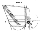
- Fig. 2 is now the hedging device 30 according to the invention with the barrier according to the invention in its basic position to see.
- the refuse container emptying device 20 is also in its inactive position.
- the hose member of the barrier according to the invention has been vented so that it is rolled up by the coil spring extending along the barrier. In this basic position both the coil spring and the barrier, this is extremely small and space-saving, so that the Müll hereerentleervorettivon is easily accessible.
- the barrier still has a certain flexibility, so that even now a risk of injury by bumping against the barrier is excluded.
- the hose member is automatically vented, being inflated by the incoming compressed air, the hose member and the barrier is extended against the force of the coil spring. Due to the flexibility of the material of the barrier and the filling with air injury is excluded by the movement of the barrier in its securing position.
- the hose element consists of a robust PE hose, so that the protection device according to the invention is durable and durable.
- the coil spring is inserted into the PE tube, wherein the coil spring and the PE tube on one side with the refuse truck 10 are connected.
- This connection is advantageously designed detachable, so that the barrier can be easily replaced.
- a connection by screwing or Aufstekken to a pressure connection is conceivable, so that simultaneously with the compressed air connection and a frictional connection is made.
Landscapes
- Engineering & Computer Science (AREA)
- Mechanical Engineering (AREA)
- Refuse-Collection Vehicles (AREA)
Claims (14)
- Dispositif de sécurité (30) pour sécuriser une zone de travail d'un dispositif de vidage des poubelles (20), avec une barrière qui peut être amenée d'une position de base dans une position de sécurité,
caractérisé en ce que la barrière est réalisée en un matériau flexible. - Dispositif de sécurité (30) selon la revendication 1, où la barrière comprend un élément tubulaire.
- Dispositif de sécurité (30) selon la revendication 2, où la barrière est amenée par aération de l'élément tubulaire de la position de base dans la position de sécurité.
- Dispositif de sécurité (30) selon la revendication 2, où la barrière se déplace par désaération de l'élément tubulaire de la position de sécurité dans la position de base.
- Dispositif de sécurité (30) selon la revendication 1, où la barrière comprend un élément élastique.
- Dispositif de sécurité (30) selon la revendication 5, où l'élément élastique s'étend le long de la barrière.
- Dispositif de sécurité (30) selon la revendication 5, où l'élément élastique comprend un ressort spiral.
- Dispositif de sécurité (30) selon la revendication 5, où la position de base de la barrière correspond à la position de base de l'élément élastique.
- Dispositif de sécurité (30) selon la revendication 1, où la barrière, dans sa position de base, est enroulée en spirale.
- Dispositif de sécurité (30) selon la revendication 1, où la barrière est déplacée lors de l'actionnement du dispositif de vidage des poubelles (20) automatiquement de la position de base dans la position de sécurité.
- Dispositif de sécurité (30) selon la revendication 1, où la barrière est déplacée dans le cas d'un dispositif de vidage inactivé des poubelles (20) automatiquement de la position de sécurité dans la position de base.
- Camion de collecte (10) avec un dispositif de vidage des poubelles (20) et un dispositif de sécurité (30) selon l'une des revendications précédentes.
- Camion de collecte (10) selon la revendication 12, où la barrière du dispositif de sécurité (30) est disposée à côté de la zone de travail du dispositif de vidage des poubelles (20).
- Camion de collecte (10) selon la revendication 12, où la barrière du dispositif de sécurité (30) est disposée au côté arrière au camion de collecte (10).
Applications Claiming Priority (1)
| Application Number | Priority Date | Filing Date | Title |
|---|---|---|---|
| DE200620007229 DE202006007229U1 (de) | 2006-05-05 | 2006-05-05 | Absicherungsvorrichtung |
Publications (2)
| Publication Number | Publication Date |
|---|---|
| EP1852368A1 EP1852368A1 (fr) | 2007-11-07 |
| EP1852368B1 true EP1852368B1 (fr) | 2008-10-29 |
Family
ID=38141163
Family Applications (1)
| Application Number | Title | Priority Date | Filing Date |
|---|---|---|---|
| EP20070009061 Not-in-force EP1852368B1 (fr) | 2006-05-05 | 2007-05-04 | Dispositif de protection |
Country Status (2)
| Country | Link |
|---|---|
| EP (1) | EP1852368B1 (fr) |
| DE (2) | DE202006007229U1 (fr) |
Cited By (1)
| Publication number | Priority date | Publication date | Assignee | Title |
|---|---|---|---|---|
| DE102013223840A1 (de) | 2013-11-21 | 2015-05-21 | Zöller-Kipper GmbH | Sicherheitsvorrichtung |
Families Citing this family (1)
| Publication number | Priority date | Publication date | Assignee | Title |
|---|---|---|---|---|
| CN111646065A (zh) * | 2020-06-05 | 2020-09-11 | 安徽丰源新能源环卫科技有限公司 | 一种垃圾运输车上料压缩下料机构 |
Family Cites Families (8)
| Publication number | Priority date | Publication date | Assignee | Title |
|---|---|---|---|---|
| DE2405997A1 (de) * | 1974-02-08 | 1975-08-21 | Bosch Gmbh Robert | Elektrischer schalter, insbesondere zugschalter |
| US4579826A (en) * | 1983-09-30 | 1986-04-01 | Bolton Craig E | Method and device for analyzing human breath |
| GB8518795D0 (en) * | 1985-07-25 | 1985-08-29 | Clark Peter John | Road traffic sign |
| GB9000184D0 (en) * | 1990-01-04 | 1990-03-07 | Timpex Limited | Novelties |
| DE29712512U1 (de) * | 1997-07-15 | 1997-09-11 | Zöller-Kipper GmbH, 55130 Mainz | Vorrichtung zum Absichern des Arbeitsbereiches von Entleereinrichtungen |
| DE29903065U1 (de) * | 1999-02-22 | 1999-07-22 | Zöller-Kipper GmbH, 55130 Mainz | Entleervorrichtung |
| WO2004045908A2 (fr) * | 2002-11-14 | 2004-06-03 | Indiana Mills & Manufacturing, Inc. | Systeme de securite pour vehicule |
| DE102004036363B4 (de) * | 2004-07-22 | 2006-11-23 | Zöller-Kipper GmbH | Verfahren und Vorrichtung zur Absicherung des Arbeitsbereiches von Entleervorrichtungen |
-
2006
- 2006-05-05 DE DE200620007229 patent/DE202006007229U1/de not_active Expired - Lifetime
-
2007
- 2007-05-04 DE DE200750000195 patent/DE502007000195D1/de active Active
- 2007-05-04 EP EP20070009061 patent/EP1852368B1/fr not_active Not-in-force
Cited By (2)
| Publication number | Priority date | Publication date | Assignee | Title |
|---|---|---|---|---|
| DE102013223840A1 (de) | 2013-11-21 | 2015-05-21 | Zöller-Kipper GmbH | Sicherheitsvorrichtung |
| EP2876058A1 (fr) | 2013-11-21 | 2015-05-27 | Zöller-Kipper GmbH | Dispositif de sécurité |
Also Published As
| Publication number | Publication date |
|---|---|
| DE502007000195D1 (de) | 2008-12-11 |
| EP1852368A1 (fr) | 2007-11-07 |
| DE202006007229U1 (de) | 2007-09-13 |
Similar Documents
| Publication | Publication Date | Title |
|---|---|---|
| EP1915185B1 (fr) | Seringue | |
| EP2054195B1 (fr) | Pince avec axe d'articulation mobile contre la force d'un ressort | |
| EP2200702A1 (fr) | Coulisseau de sécurité pour système de protection contre les chutes | |
| EP0399253A1 (fr) | Barre de timonerie pour véhicules à moteur | |
| EP2255693A1 (fr) | Mécanisme de verrouillage | |
| EP0940203A2 (fr) | Outil de rivetage à main pour rivets aveugles | |
| EP1852368B1 (fr) | Dispositif de protection | |
| DE19805474C1 (de) | Teleskopstütze | |
| AT408475B (de) | Anordnung zur hydraulischen betätigung eines beweglichen bauteils an einem fahrzeug | |
| EP4046879A1 (fr) | Dispositif de protection pour une face avant de cabine de véhicule de travail | |
| DE60112694T2 (de) | Feuerschlauch mit einem Sicherungsgerät zum Verhindern, dass sich der Schlauch unter dem ihm speisenden Wasserdruck bewegt | |
| EP2974707B1 (fr) | Grille laterale | |
| EP2959800B1 (fr) | Meuble avec un dispositif destiné à l'accouplement amovible d'un chargeur intérieur sur un chargeur extérieur d'un meuble | |
| DE4239599C2 (de) | Handbetätigte Verschließvorrichtung für Wagenkästen und Container | |
| CH682303A5 (fr) | ||
| DE102015220668A1 (de) | Klapp- und schwenkbarer Stützklappgriff, insbesondere für den Sanitärbereich | |
| DE69932046T2 (de) | Ladungstützvorrichtung | |
| DE2644649C3 (de) | Schildausbaugestell | |
| DE20314002U1 (de) | Mischwagen | |
| EP1785060A1 (fr) | Guide lateral pour un élément d'extraction d'un tiroir vertical | |
| DE102017211709B4 (de) | Türkantenschutzeinrichtung | |
| DE602004003160T2 (de) | Vorrichtung zur Sammlung von medizinischen Abfällen | |
| DE10354158A1 (de) | Vorrichtung zum Aufstellen einer Fahrzeug-Tür, insbesondere einer Kfz-Fronthaube, in einer Unfallsituation | |
| DE102015108592A1 (de) | Schirm mit einer Vorrichtung zum automatischen Schließen bei Wind | |
| DE4126600C2 (de) | Transportgreifer mit Sperreinrichtung |
Legal Events
| Date | Code | Title | Description |
|---|---|---|---|
| PUAI | Public reference made under article 153(3) epc to a published international application that has entered the european phase |
Free format text: ORIGINAL CODE: 0009012 |
|
| AK | Designated contracting states |
Kind code of ref document: A1 Designated state(s): AT BE BG CH CY CZ DE DK EE ES FI FR GB GR HU IE IS IT LI LT LU LV MC MT NL PL PT RO SE SI SK TR |
|
| AX | Request for extension of the european patent |
Extension state: AL BA HR MK YU |
|
| 17P | Request for examination filed |
Effective date: 20071115 |
|
| GRAP | Despatch of communication of intention to grant a patent |
Free format text: ORIGINAL CODE: EPIDOSNIGR1 |
|
| GRAS | Grant fee paid |
Free format text: ORIGINAL CODE: EPIDOSNIGR3 |
|
| AKX | Designation fees paid |
Designated state(s): BE DE FR LU NL |
|
| GRAA | (expected) grant |
Free format text: ORIGINAL CODE: 0009210 |
|
| AK | Designated contracting states |
Kind code of ref document: B1 Designated state(s): BE DE FR LU NL |
|
| REF | Corresponds to: |
Ref document number: 502007000195 Country of ref document: DE Date of ref document: 20081211 Kind code of ref document: P |
|
| PLBE | No opposition filed within time limit |
Free format text: ORIGINAL CODE: 0009261 |
|
| STAA | Information on the status of an ep patent application or granted ep patent |
Free format text: STATUS: NO OPPOSITION FILED WITHIN TIME LIMIT |
|
| 26N | No opposition filed |
Effective date: 20090730 |
|
| PGFP | Annual fee paid to national office [announced via postgrant information from national office to epo] |
Ref country code: NL Payment date: 20120531 Year of fee payment: 6 Ref country code: DE Payment date: 20120531 Year of fee payment: 6 Ref country code: LU Payment date: 20120531 Year of fee payment: 6 |
|
| PGFP | Annual fee paid to national office [announced via postgrant information from national office to epo] |
Ref country code: BE Payment date: 20120531 Year of fee payment: 6 Ref country code: FR Payment date: 20120614 Year of fee payment: 6 |
|
| BERE | Be: lapsed |
Owner name: FAUN UMWELTTECHNIK G.M.B.H. & CO. KG Effective date: 20130531 |
|
| REG | Reference to a national code |
Ref country code: NL Ref legal event code: V1 Effective date: 20131201 |
|
| PG25 | Lapsed in a contracting state [announced via postgrant information from national office to epo] |
Ref country code: DE Free format text: LAPSE BECAUSE OF NON-PAYMENT OF DUE FEES Effective date: 20131203 |
|
| REG | Reference to a national code |
Ref country code: DE Ref legal event code: R119 Ref document number: 502007000195 Country of ref document: DE Effective date: 20131203 |
|
| PG25 | Lapsed in a contracting state [announced via postgrant information from national office to epo] |
Ref country code: BE Free format text: LAPSE BECAUSE OF NON-PAYMENT OF DUE FEES Effective date: 20130531 Ref country code: NL Free format text: LAPSE BECAUSE OF NON-PAYMENT OF DUE FEES Effective date: 20131201 |
|
| REG | Reference to a national code |
Ref country code: FR Ref legal event code: ST Effective date: 20140131 |
|
| PG25 | Lapsed in a contracting state [announced via postgrant information from national office to epo] |
Ref country code: FR Free format text: LAPSE BECAUSE OF NON-PAYMENT OF DUE FEES Effective date: 20130531 |
|
| PG25 | Lapsed in a contracting state [announced via postgrant information from national office to epo] |
Ref country code: LU Free format text: LAPSE BECAUSE OF NON-PAYMENT OF DUE FEES Effective date: 20130504 |