EP1852564A2 - Fixation de tuyau, en particulier pour des tuyaux d'extrémité sur des mâts de pompes à béton - Google Patents
Fixation de tuyau, en particulier pour des tuyaux d'extrémité sur des mâts de pompes à béton Download PDFInfo
- Publication number
- EP1852564A2 EP1852564A2 EP07105848A EP07105848A EP1852564A2 EP 1852564 A2 EP1852564 A2 EP 1852564A2 EP 07105848 A EP07105848 A EP 07105848A EP 07105848 A EP07105848 A EP 07105848A EP 1852564 A2 EP1852564 A2 EP 1852564A2
- Authority
- EP
- European Patent Office
- Prior art keywords
- hose
- lever
- hose holder
- holder according
- arm
- Prior art date
- Legal status (The legal status is an assumption and is not a legal conclusion. Google has not performed a legal analysis and makes no representation as to the accuracy of the status listed.)
- Withdrawn
Links
Images

Classifications
-
- E—FIXED CONSTRUCTIONS
- E04—BUILDING
- E04G—SCAFFOLDING; FORMS; SHUTTERING; BUILDING IMPLEMENTS OR AIDS, OR THEIR USE; HANDLING BUILDING MATERIALS ON THE SITE; REPAIRING, BREAKING-UP OR OTHER WORK ON EXISTING BUILDINGS
- E04G21/00—Preparing, conveying, or working-up building materials or building elements in situ; Other devices or measures for constructional work
- E04G21/02—Conveying or working-up concrete or similar masses able to be heaped or cast
- E04G21/04—Devices for both conveying and distributing
- E04G21/0418—Devices for both conveying and distributing with distribution hose
-
- F—MECHANICAL ENGINEERING; LIGHTING; HEATING; WEAPONS; BLASTING
- F16—ENGINEERING ELEMENTS AND UNITS; GENERAL MEASURES FOR PRODUCING AND MAINTAINING EFFECTIVE FUNCTIONING OF MACHINES OR INSTALLATIONS; THERMAL INSULATION IN GENERAL
- F16L—PIPES; JOINTS OR FITTINGS FOR PIPES; SUPPORTS FOR PIPES, CABLES OR PROTECTIVE TUBING; MEANS FOR THERMAL INSULATION IN GENERAL
- F16L3/00—Supports for pipes, cables or protective tubing, e.g. hangers, holders, clamps, cleats, clips, brackets
- F16L3/003—Supports for pipes, cables or protective tubing, e.g. hangers, holders, clamps, cleats, clips, brackets devices for holding the open end of a hose
-
- F—MECHANICAL ENGINEERING; LIGHTING; HEATING; WEAPONS; BLASTING
- F16—ENGINEERING ELEMENTS AND UNITS; GENERAL MEASURES FOR PRODUCING AND MAINTAINING EFFECTIVE FUNCTIONING OF MACHINES OR INSTALLATIONS; THERMAL INSULATION IN GENERAL
- F16L—PIPES; JOINTS OR FITTINGS FOR PIPES; SUPPORTS FOR PIPES, CABLES OR PROTECTIVE TUBING; MEANS FOR THERMAL INSULATION IN GENERAL
- F16L55/00—Devices or appurtenances for use in, or in connection with, pipes or pipe systems
- F16L55/005—Devices restraining ruptured tubes from whipping
Definitions
- the invention relates to a hose holder, in particular for end hoses to concrete distribution masts, with an open at the edge in the region of two hanger arms retaining bracket for receiving a hose end and with a hinged at the opening edge of a hanger arm two-armed safety lever.
- Hose holders of this type are used, for example, on the end arm of a concrete distributor mast for receiving an end hose in the transport state of the distributor boom. They have the task of holding the end hose in its transport position parallel to the end arm and, if necessary, releasing it into its concreting position hanging down at the end arm.
- the solution according to the invention is primarily seen in the fact that the first lever arm of the safety lever engages from the articulation point with an outer insertion bevel and an inner stop surface in the inside of the temple and that the second lever arm engages on the outside of the articulation point of a bar leg and under the action of Gravity and / or a spring force against it bears against the outside, during the first lever arm, the edge opening partially overlaps, wherein the locking lever via the insertion of the first lever arm during insertion of the end hose or by hand on the second lever arm against the gravity and / or spring force releasing the edge opening of the retaining clip for the passage of the end hose is limited pivotally.
- the inner stop surface according to the invention on the first lever arm ensures that the end hose, which is in the transport state in the retaining clip, can not accidentally come out of the retaining clip.
- the safety lever is pivoted against the heavy and / or spring force on the second lever arm.
- a preferred embodiment of the invention provides that a leaf spring is clamped between the one bar leg and the safety lever.
- the leaf spring is expediently fixed at one end to the one hanger arm and lies with its other end against at least one arranged on the safety lever driver.
- a further preferred embodiment of the invention provides that the safety lever is composed mainly of stamped and bent parts made of sheet metal.
- the leaf spring is expediently arranged within the pocket forming the safety lever, while the driver bears against the leaf spring within the pocket.
- the main directions of the two lever arms of the safety lever suitably close from the articulation point from an acute angle with each other.
- a further advantageous embodiment of the invention provides that the headband has a U-shaped curvedrawpartie for the end hose as well as an on a bracket leg obliquely outwardly projecting, the pivot point having edge portion.
- the headband expediently has an edge-side, inclined to the bow opening chamfer for the end hose and possibly a projecting after the ironing outsole mounting bracket.
- the invention also relates to a truck-mounted concrete pump with a trained as a carrier for a concrete delivery line, composed of several Mastarmen articulated mast, the delivery line in the end arm wearing a end hose and in which the end of the Knickmasts at least two spaced-apart hose holder according to the invention for receiving the End hose carries.
- the hose holder according to the invention are fixed with their mounting brackets on the end of the buckling mast.
- the hose holder shown in the drawing is intended for mounting on the end arm of a concrete distributor boom, which is designed as a carrier for a concrete delivery line.
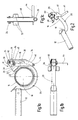
- two of the tube holders 10 are fixed at the end arm of the articulated mast arms composed of several mast arms spaced from each other with their mounting brackets 12, which are there in the folded transport state of the articulated mast for receiving the hinged at the end of the delivery line in the end arm 14.
- the hose holder has a retaining bracket 20 which is open on the edge side in the region of two stirrup legs 16, 18 for receiving the end hose 14 and a two-armed securing lever 26 hinged on the opening edge 22 of the stirrup leg 16 via an axle pin 24.
- the one lever arm 28 of the safety lever 26 engages from the articulation point 24 with an outer insertion 30 and an inner stop surface 32 in the temple interior.
- the second lever arm 34 engages over the stirrup leg 16 on the outside and abuts against the latter on the outside under the action of gravity and / or the force of a spring 36 designed, for example, as a leaf spring, while the first lever arm 28 partially overlaps the edge opening of the stirrup.
- the safety lever 26 is limited by the insertion 30 of the first lever arm 28 during insertion of the end hose 14 or by hand on the second lever arm 34 against the gravity and / or spring force releasing the edge opening of the retaining clip 20 for the passage of the end hose 14 pivotally limited.
- the safety lever 26 At a distance from the articulation point (axle pin 24) 16 are arranged in one slot guide 38 of the safety lever 26 engaging two guide pins 40 on the one leg 16.
- the two slot guides 38 form concentric circular segments whose centers are defined by the axle pin 24.
- the pivotal movement of the safety lever 26 is limited by end stops at the ends of the slot guide 38.
- the second lever arm 34 At one of the end stops, the second lever arm 34 is under the action of gravity and / or spring force substantially parallel to a hanger arm 16 aligned (Fig. 1a). In this position, the first lever arm 28 blocks with its stop surface 32, the edge opening of the retaining clip 20.
- the edge opening of the safety lever 26 can be detected on a handle 44, which is arranged at the end of the second lever arm 34 and parallel to the axis defined by the axle 24 Anschachse is aligned.
- the main directions of the two lever arms 28, 34 form an acute angle with one another from the point of articulation 24.
- the second lever arm 34 has an outer bevel 46 which extends toward its end carrying the handle 44 and which ensures that it takes up little space, especially in the pivoted-in state.
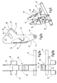
- the safety lever 26 is composed predominantly of punched and bent parts made of sheet metal. It forms an opening to the headband 20 towards open pocket 48, which surrounds a bar leg 16 partially.
- the leaf spring 36 is arranged as well as her on the second lever arm 34 arranged driver 50 within the pocket 48.
- the stop surface 32 is defined by two tabs 52 which are bent laterally outwardly in the region of the first lever arm 28 on the relevant sheet metal parts 54 of the safety lever 26.
- the sheet metal parts 54 of the safety lever 26 on the side of the second lever arm 34 connecting wall 56 are connected to each other.
- the bracket leg 16 carries at its free, obliquely outwardly bent edge portion 60 an outwardly projecting bracket 62 to which the leaf spring 36 is fixed at one end by means of screws 64 (Fig. 3a, 3b, 4 and Fig. 1a).
- the safety arm 26 opposite the stirrup leg 16 carries at its free end an edge-side, inclined to the stirrup opening insertion 58.
- an edge-side, inclined to the stirrup opening insertion 58 In addition, in this area of the projecting vertically outwardly Montageanlieger 12 is welded.
- the invention relates to a hose holder, in particular for end hoses on concrete distributor masts.
- the hose holder has an edge-side in the region of two stirrup legs 16,18 open headband 20 for receiving a hose end and a hinged at the opening edge 22 of a stirrup leg 16 two-armed locking lever 26.
- the first lever arm 28 of the safety lever engages from the articulation point 24 with an outer insertion bevel 30 and an inner stop surface 32 in the temple interior.
- the second lever arm 34 engages over from the articulation point 24 of a bar leg 16 on the outside and is under the action of gravity and / or a spring force against this on the outside, while the first lever arm 28, the edge opening partially overlaps.
- the locking lever 26 is limited by the insertion 30 of the first lever arm 28 during insertion of the end hose 14 or by hand on the second lever arm 34 against the gravity and / or spring force releasing the edge opening of the retaining clip 20 for the passage of the end hose 14 pivotally limited.
Landscapes
- Engineering & Computer Science (AREA)
- General Engineering & Computer Science (AREA)
- Mechanical Engineering (AREA)
- Architecture (AREA)
- Civil Engineering (AREA)
- Structural Engineering (AREA)
- Supports For Pipes And Cables (AREA)
Applications Claiming Priority (1)
| Application Number | Priority Date | Filing Date | Title |
|---|---|---|---|
| DE102006020928A DE102006020928A1 (de) | 2006-05-05 | 2006-05-05 | Schlauchhalter, insbesondere für Endschläuche an Betonverteilermasten |
Publications (2)
| Publication Number | Publication Date |
|---|---|
| EP1852564A2 true EP1852564A2 (fr) | 2007-11-07 |
| EP1852564A3 EP1852564A3 (fr) | 2009-08-19 |
Family
ID=38267623
Family Applications (1)
| Application Number | Title | Priority Date | Filing Date |
|---|---|---|---|
| EP07105848A Withdrawn EP1852564A3 (fr) | 2006-05-05 | 2007-04-10 | Fixation de tuyau, en particulier pour des tuyaux d'extrémité sur des mâts de pompes à béton |
Country Status (2)
| Country | Link |
|---|---|
| EP (1) | EP1852564A3 (fr) |
| DE (1) | DE102006020928A1 (fr) |
Cited By (3)
| Publication number | Priority date | Publication date | Assignee | Title |
|---|---|---|---|---|
| AT520543B1 (de) * | 2018-01-23 | 2019-05-15 | Schwing Gmbh F | Großmanipulator mit Endschlauchhalter |
| CN111255951A (zh) * | 2020-01-16 | 2020-06-09 | 中铁二局集团有限公司 | 超高层建筑施工混凝土泵管固定结构 |
| CN111971440A (zh) * | 2018-03-22 | 2020-11-20 | 普茨迈斯特工程有限责任公司 | 用于混凝土泵的分配杆的端部软管支架、具有端部软管支架的混凝土泵以及一种用于组装端部软管支架的方法 |
Families Citing this family (1)
| Publication number | Priority date | Publication date | Assignee | Title |
|---|---|---|---|---|
| DE102015108473A1 (de) * | 2015-05-28 | 2016-12-01 | Schwing Gmbh | Großmanipulator mit schnell ein- und ausfaltbarem Knickmast |
Family Cites Families (4)
| Publication number | Priority date | Publication date | Assignee | Title |
|---|---|---|---|---|
| US2752190A (en) * | 1952-10-10 | 1956-06-26 | Wavy L Baker | Hand rod hook |
| DE3128496A1 (de) * | 1981-07-18 | 1983-02-03 | Stetter Gmbh, 8940 Memmingen | Halterung fuer foerderrohre insbesondere bei betonpumpen |
| DE29814417U1 (de) * | 1998-08-11 | 1998-10-08 | Kuka Roboter GmbH, 86165 Augsburg | Schlauchhalter |
| DE20205345U1 (de) * | 2002-04-06 | 2002-06-27 | Johann Sauer Eisenwarenfabrik GmbH & Co. KG, 61389 Schmitten | Rohrschelle |
-
2006
- 2006-05-05 DE DE102006020928A patent/DE102006020928A1/de not_active Withdrawn
-
2007
- 2007-04-10 EP EP07105848A patent/EP1852564A3/fr not_active Withdrawn
Non-Patent Citations (1)
| Title |
|---|
| None |
Cited By (5)
| Publication number | Priority date | Publication date | Assignee | Title |
|---|---|---|---|---|
| AT520543B1 (de) * | 2018-01-23 | 2019-05-15 | Schwing Gmbh F | Großmanipulator mit Endschlauchhalter |
| AT520543A4 (de) * | 2018-01-23 | 2019-05-15 | Schwing Gmbh F | Großmanipulator mit Endschlauchhalter |
| US11365551B2 (en) | 2018-01-23 | 2022-06-21 | Schwing Gmbh | Large manipulator with end-hose holder |
| CN111971440A (zh) * | 2018-03-22 | 2020-11-20 | 普茨迈斯特工程有限责任公司 | 用于混凝土泵的分配杆的端部软管支架、具有端部软管支架的混凝土泵以及一种用于组装端部软管支架的方法 |
| CN111255951A (zh) * | 2020-01-16 | 2020-06-09 | 中铁二局集团有限公司 | 超高层建筑施工混凝土泵管固定结构 |
Also Published As
| Publication number | Publication date |
|---|---|
| EP1852564A3 (fr) | 2009-08-19 |
| DE102006020928A1 (de) | 2007-11-08 |
Similar Documents
| Publication | Publication Date | Title |
|---|---|---|
| DE202005021825U1 (de) | Vorrichtung, die zum Halten einer Komponente geeignet ist | |
| EP2745739B1 (fr) | Dispositif d'accroche pour meuble mural | |
| DE102015102388A1 (de) | Schiebe-Schwenkmechanik einer Ablage eines Möbels und Möbel | |
| EP1852564A2 (fr) | Fixation de tuyau, en particulier pour des tuyaux d'extrémité sur des mâts de pompes à béton | |
| DE202005005737U1 (de) | Stammgelenk für einen künstlichen Baum | |
| DE202019001296U1 (de) | Schalungsbühne | |
| DE2455408A1 (de) | Tragvorrichtung | |
| DE202007014620U1 (de) | Aufhängehaken | |
| DE202013100020U1 (de) | Vorrichtung zur Verstellung eines Möbelstücks | |
| DE102004012833A1 (de) | Tragbare Mobilbox | |
| WO1999020162A1 (fr) | Dispositif couvercle d'un recipient | |
| DE112011104806B4 (de) | Verbindungsbeschlag | |
| DE202004002161U1 (de) | Verkürzungsklaue | |
| DE4304615C2 (de) | Kraftfahrzeugtür mit einem mittels einer Feder belasteten Feststellarm zum Fixieren der Tür in einer 90 DEG - und einer 180 DEG -Rastposition | |
| EP1740494B1 (fr) | Crochet servant a fixer une elingue sur un conteneur | |
| DE3400780C2 (fr) | ||
| WO1996029910A1 (fr) | Dispositif permettant de moduler la hauteur et/ou l'inclinaison du plateau d'une table | |
| DE202013005158U1 (de) | Befestigungseinrichtung zur Montage einer Halteklammer und andere Beschläge in einer gelochten dünnen Wand | |
| DE10255573B4 (de) | Türaußengriffanordnung für ein Kraftfahrzeug | |
| DE19820183C1 (de) | Klappstecker zur lösbaren Sicherung von Bolzen | |
| DE19615785C1 (de) | Aufhänger für Einhängeelemente | |
| DE202024105126U1 (de) | Wandhalterung für ein Musikinstrument | |
| DE4423373A1 (de) | Einrichtung zum Befestigen von Taschen | |
| DE20102433U1 (de) | Rohrpostbüchse | |
| DE9017364U1 (de) | Kabelklemme |
Legal Events
| Date | Code | Title | Description |
|---|---|---|---|
| PUAI | Public reference made under article 153(3) epc to a published international application that has entered the european phase |
Free format text: ORIGINAL CODE: 0009012 |
|
| AK | Designated contracting states |
Kind code of ref document: A2 Designated state(s): AT BE BG CH CY CZ DE DK EE ES FI FR GB GR HU IE IS IT LI LT LU LV MC MT NL PL PT RO SE SI SK TR |
|
| AX | Request for extension of the european patent |
Extension state: AL BA HR MK YU |
|
| RAP1 | Party data changed (applicant data changed or rights of an application transferred) |
Owner name: PUTZMEISTER CONCRETE PUMPS GMBH |
|
| PUAL | Search report despatched |
Free format text: ORIGINAL CODE: 0009013 |
|
| AK | Designated contracting states |
Kind code of ref document: A3 Designated state(s): AT BE BG CH CY CZ DE DK EE ES FI FR GB GR HU IE IS IT LI LT LU LV MC MT NL PL PT RO SE SI SK TR |
|
| AX | Request for extension of the european patent |
Extension state: AL BA HR MK RS |
|
| RIC1 | Information provided on ipc code assigned before grant |
Ipc: F16L 3/13 20060101ALI20090713BHEP Ipc: F16L 3/02 20060101ALI20090713BHEP Ipc: F16L 3/00 20060101ALI20090713BHEP Ipc: E04G 21/04 20060101AFI20070726BHEP |
|
| AKX | Designation fees paid | ||
| STAA | Information on the status of an ep patent application or granted ep patent |
Free format text: STATUS: THE APPLICATION IS DEEMED TO BE WITHDRAWN |
|
| 18D | Application deemed to be withdrawn |
Effective date: 20100220 |
|
| REG | Reference to a national code |
Ref country code: DE Ref legal event code: 8566 |