EP1852579A1 - Ölwanne für einen Verbrennungsmotor - Google Patents
Ölwanne für einen Verbrennungsmotor Download PDFInfo
- Publication number
- EP1852579A1 EP1852579A1 EP07107306A EP07107306A EP1852579A1 EP 1852579 A1 EP1852579 A1 EP 1852579A1 EP 07107306 A EP07107306 A EP 07107306A EP 07107306 A EP07107306 A EP 07107306A EP 1852579 A1 EP1852579 A1 EP 1852579A1
- Authority
- EP
- European Patent Office
- Prior art keywords
- oil
- oil pan
- connecting plate
- engine block
- tub body
- Prior art date
- Legal status (The legal status is an assumption and is not a legal conclusion. Google has not performed a legal analysis and makes no representation as to the accuracy of the status listed.)
- Granted
Links
- 238000002485 combustion reaction Methods 0.000 title claims description 4
- 229920002994 synthetic fiber Polymers 0.000 claims abstract description 8
- 230000002093 peripheral effect Effects 0.000 claims abstract description 3
- 239000003921 oil Substances 0.000 claims description 26
- 229910052782 aluminium Inorganic materials 0.000 claims description 2
- XAGFODPZIPBFFR-UHFFFAOYSA-N aluminium Chemical compound [Al] XAGFODPZIPBFFR-UHFFFAOYSA-N 0.000 claims description 2
- 239000010687 lubricating oil Substances 0.000 claims description 2
- 229910052751 metal Inorganic materials 0.000 claims 1
- 239000002184 metal Substances 0.000 claims 1
- 238000003466 welding Methods 0.000 description 2
- 241001295925 Gegenes Species 0.000 description 1
- 238000010438 heat treatment Methods 0.000 description 1
- 238000004519 manufacturing process Methods 0.000 description 1
- 238000000034 method Methods 0.000 description 1
- 238000010992 reflux Methods 0.000 description 1
Images

Classifications
-
- F—MECHANICAL ENGINEERING; LIGHTING; HEATING; WEAPONS; BLASTING
- F01—MACHINES OR ENGINES IN GENERAL; ENGINE PLANTS IN GENERAL; STEAM ENGINES
- F01M—LUBRICATING OF MACHINES OR ENGINES IN GENERAL; LUBRICATING INTERNAL COMBUSTION ENGINES; CRANKCASE VENTILATING
- F01M11/00—Component parts, details or accessories, not provided for in, or of interest apart from, groups F01M1/00 - F01M9/00
- F01M11/0004—Oilsumps
-
- F—MECHANICAL ENGINEERING; LIGHTING; HEATING; WEAPONS; BLASTING
- F01—MACHINES OR ENGINES IN GENERAL; ENGINE PLANTS IN GENERAL; STEAM ENGINES
- F01M—LUBRICATING OF MACHINES OR ENGINES IN GENERAL; LUBRICATING INTERNAL COMBUSTION ENGINES; CRANKCASE VENTILATING
- F01M11/00—Component parts, details or accessories, not provided for in, or of interest apart from, groups F01M1/00 - F01M9/00
- F01M11/0004—Oilsumps
- F01M2011/005—Oilsumps with special anti-turbulence means, e.g. anti-foaming means or intermediate plates
-
- F—MECHANICAL ENGINEERING; LIGHTING; HEATING; WEAPONS; BLASTING
- F01—MACHINES OR ENGINES IN GENERAL; ENGINE PLANTS IN GENERAL; STEAM ENGINES
- F01M—LUBRICATING OF MACHINES OR ENGINES IN GENERAL; LUBRICATING INTERNAL COMBUSTION ENGINES; CRANKCASE VENTILATING
- F01M11/00—Component parts, details or accessories, not provided for in, or of interest apart from, groups F01M1/00 - F01M9/00
- F01M11/0004—Oilsumps
- F01M2011/0054—Fastening to the cylinder block
-
- F—MECHANICAL ENGINEERING; LIGHTING; HEATING; WEAPONS; BLASTING
- F01—MACHINES OR ENGINES IN GENERAL; ENGINE PLANTS IN GENERAL; STEAM ENGINES
- F01M—LUBRICATING OF MACHINES OR ENGINES IN GENERAL; LUBRICATING INTERNAL COMBUSTION ENGINES; CRANKCASE VENTILATING
- F01M11/00—Component parts, details or accessories, not provided for in, or of interest apart from, groups F01M1/00 - F01M9/00
- F01M11/0004—Oilsumps
- F01M2011/0062—Gaskets
-
- F—MECHANICAL ENGINEERING; LIGHTING; HEATING; WEAPONS; BLASTING
- F01—MACHINES OR ENGINES IN GENERAL; ENGINE PLANTS IN GENERAL; STEAM ENGINES
- F01M—LUBRICATING OF MACHINES OR ENGINES IN GENERAL; LUBRICATING INTERNAL COMBUSTION ENGINES; CRANKCASE VENTILATING
- F01M11/00—Component parts, details or accessories, not provided for in, or of interest apart from, groups F01M1/00 - F01M9/00
- F01M11/0004—Oilsumps
- F01M2011/007—Oil pickup tube to oil pump, e.g. strainer
-
- F—MECHANICAL ENGINEERING; LIGHTING; HEATING; WEAPONS; BLASTING
- F01—MACHINES OR ENGINES IN GENERAL; ENGINE PLANTS IN GENERAL; STEAM ENGINES
- F01M—LUBRICATING OF MACHINES OR ENGINES IN GENERAL; LUBRICATING INTERNAL COMBUSTION ENGINES; CRANKCASE VENTILATING
- F01M11/00—Component parts, details or accessories, not provided for in, or of interest apart from, groups F01M1/00 - F01M9/00
- F01M11/0004—Oilsumps
- F01M2011/0087—Sump being made of different parts
-
- F—MECHANICAL ENGINEERING; LIGHTING; HEATING; WEAPONS; BLASTING
- F01—MACHINES OR ENGINES IN GENERAL; ENGINE PLANTS IN GENERAL; STEAM ENGINES
- F01M—LUBRICATING OF MACHINES OR ENGINES IN GENERAL; LUBRICATING INTERNAL COMBUSTION ENGINES; CRANKCASE VENTILATING
- F01M11/00—Component parts, details or accessories, not provided for in, or of interest apart from, groups F01M1/00 - F01M9/00
- F01M11/0004—Oilsumps
- F01M2011/0091—Oilsumps characterised by used materials
Definitions
- the essential feature of the oil sump which is the subject of the invention is thus bound to the presence of the connecting plate of synthetic material, which represents an interface, which makes it possible to achieve the necessary tightness between the bucket body and the engine block thanks to the presence of two circumferential seals , which are poured onto their respective surfaces, and at the same time allows to suck with the oil pump located in the interior of the tub body lubricating oil.
- connection plate must of course be provided with passage openings for the oil that runs back into the tub body and with holes for the shaft of the mounting screws of the oil pan on the engine block housing.
- the body of the bath consists of an element in the form of a vessel whose lower wall is inclined and which at the lower end is provided with a discharge opening which is closed by a closure lid.
- the oil sump which is the subject of the invention, differs from the conventional aluminum sumps by their lower weight and by significantly lower manufacturing and assembly costs.
- the tub body is formed by the assembly of two shells, ie a lower shell in the form of a vessel and an upper shell which is welded thereto and contains the connection plate.
- the connecting plate and the upper shell are thus between the lower shell and the engine block of the internal combustion engine.
- These two shells can preferably be welded without contact by means of a heating plate.
- Such a welding method has the advantage that one obtains very small welds compared especially with a conventional vibration welding.
- the oil sump according to the invention can have a significantly higher capacity than the conventional and comparable oil sumps currently available on the market.
- the bottom wall of the lower shell extends upwards by means of tubular, parallel columns having at their upper end a shoulder which forms a stop for the head of the mounting screw of the oil pan on the engine block housing.
- the upper shell and the connecting plate are provided with paired holes for the shanks of these screws so that they can be screwed onto the lower wall of the engine block housing and compress the two circumferential seals which are poured onto the connecting plate between the upper shell and the engine block housing to ensure a radial tightness between the oil pan and the engine block.
- the oil pan consists of a tub body 1 made of synthetic material, which is closed at its upper part by a connecting plate 2, also made of synthetic material.
- the tub body 1 is fastened by means of the fastening screws 3 on the engine block housing of the internal combustion engine, which is not shown here in the figures.
- connection plate 2 is located between the tub body 1 and the engine block housing.
- the connecting plate 2 extends on its lower surface by means of a tubular fitting 5 which surrounds a suction port 7 and is provided at its free end with a filter net 6.
- This tubular fitting 5 forms a segment of a suction pipe which is connected to an oil pump not shown in the figures so as to guide the oil stored in the body 1 to the various parts of the engine which need to be lubricated.
- connection plate 2 The holes 4 bored on the surface of the connection plate 2 allow the excess oil to reflux into the tub body 1.
- the connecting plate 2 is provided on each of its sides with a peripheral seal 8, 9 and poured thereon.
- the connecting plate 2 is also provided on its periphery with a series of holes 19, 20, which aim to receive the shank of the fastening screws.
- the tub body 1 is formed by assembling a lower shell in the form of a vessel 10 and an upper shell 11 welded thereto at its periphery.
- the lower shell 10 is shown in more detail in Figures 5 and 6.
- the upper shell 11 is shown in more detail in Figures 7 and 8.
- the lower surface of the lower shell 10 is inclined and extends laterally via a channel 12 to a low point provided with a discharge port closed by a cap 13.
- the lower surface of the lower shell 10 also extends upwardly through a series of tubular, parallel columns 14, the purpose of which is to receive the mounting screws 3 of the tub body 1 and insert them on the engine block housing.
- the upper shell 11 has a geometry which complements that of the lower shell 10 and also extends laterally through a rib 15 corresponding to the channel 12.
- the upper shell 11 is also provided around its circumference with a ring 16 provided with bores corresponding respectively to the bores 19, 20 of the connecting plate 2 which receive the shank of the fixing screws 3.
- part of the ring 16 of the upper shell 11 projects laterally beyond the lower shell 10.
- the other pairs of holes 17, 19 are each located to the right of the upper end of a tubular column 14 of the lower shell 10 within the perimeter seals 8, 9.
- tubular columns 14 are provided at their upper end with a shoulder 21 which serves as a stop for the head 22 of a fastening screw 3.
Landscapes
- Engineering & Computer Science (AREA)
- Mechanical Engineering (AREA)
- General Engineering & Computer Science (AREA)
- Lubrication Details And Ventilation Of Internal Combustion Engines (AREA)
- Cylinder Crankcases Of Internal Combustion Engines (AREA)
Abstract
Description
- Es sei darauf hingewiesen, dass im Rahmen dieser Beschreibung die Ausdrücke "oben", "unten", "oberhalb" und "unterhalb" sich auf die auf den Motorblock montierte Ölwanne in normaler Betriebsposition beziehen.
- Das wesentliche Merkmal der Ölwanne, die Gegenstand der Erfindung ist, ist somit gebunden an das Vorhandensein der Verbindungsplatte aus synthetischem Material, welche eine Schnittstelle darstellt, die es erlaubt, die notwendige Dichtigkeit zwischen dem Wannenkörper und dem Motorblock dank des Vorhandenseins von zwei Umfangsdichtungen zu erreichen, die auf deren jeweilige Flächen gegossen werden, und welche gleichzeitig erlaubt, mit der Ölpumpe das im Inneren des Wannenkörpers befindliche Schmieröl abzusaugen.
- Diese Verbindungsplatte muss selbstverständlich mit Durchlassöffnungen für das Öl versehen sein, das in den Wannenkörper zurückläuft sowie mit Bohrungen für den Schaft der Befestigungsschrauben der Ölwanne auf dem Motorblockgehäuse.
- Was den Wannenkörper betrifft, so besteht dieser aus einem Element in Form eines Gefäßes, dessen untere Wandung geneigt ist und das am unteren Ende mit einer Ablassöffnung versehen ist, die mit einem Verschlussdeckel verschlossen ist.
- Die Ölwanne, die Gegenstand der Erfindung ist, unterscheidet sich von den herkömmlichen Ölwannen aus Aluminium durch ihr geringeres Gewicht und durch deutlich niedrigere Herstellungs- und Montagekosten.
- Gemäß eines bevorzugten Merkmals der Erfindung wird der Wannenkörper durch den Zusammenbau von zwei Schalen gebildet, d.h. einer unteren Schale in Form eines Gefäßes und einer oberen Schale, die mit dieser verschweißt ist und die Verbindungsplatte enthält.
- Die Verbindungsplatte und die obere Schale liegen somit zwischen der unteren Schale und dem Motorblock des Verbrennungsmotors.
- Diese beiden Schalen können vorzugsweise mittels einer Heizplatte kontaktlos verschweißt werden.
- Ein derartiges Schweißverfahren hat den Vorteil, dass man sehr kleine Schweißnähte erhält verglichen vor allem mit einem herkömmlichen Vibrationsschweißen.
- Hinsichtlich der Ausführungsform kann die Ölwanne erfindungsgemäß ein deutlich höheres Fassungsvermögen haben als die zur Zeit auf dem Markt angebotenen herkömmlichen und vergleichbaren Ölwannen.
- Gemäß eines weiteren Merkmals der Erfindung erstreckt sich die untere Wandung der unteren Schale nach oben mittels röhrenartiger, parallel verlaufender Säulen, die an ihrem oberen Ende einen Absatz haben, der einen Anschlag für den Kopf der Befestigungsschraube der Ölwanne auf dem Motorblockgehäuse bildet.
- Die obere Schale und die Verbindungsplatte sind mit paarweise angeordneten Bohrungen für die Schäfte dieser Schrauben versehen, damit sie auf der unteren Wandung des Motorblockgehäuses angeschraubt werden können und die beiden Umfangsdichtungen zusammenpressen, die auf die Verbindungsplatte zwischen der oberen Schale und dem Motorblockgehäuse ausgegossen werden, um so eine radiale Dichtigkeit zwischen der Ölwanne und dem Motorblock zu gewährleisten.
- Die Merkmale der Ölwanne, die Gegenstand der Erfindung ist, werden detaillierter erklärt unter Bezugnahme auf die nicht einschränkenden, beigefügten Zeichnungen, in denen
- Abb. 1 eine perspektivische Ansicht der Ölwanne ist,
- Abb. 2 eine Explosionszeichnung dieser Ölwanne ist,
- Abb. 3 eine Explosionszeichnung dieser Ölwanne ist, die der in Abb. 2 entspricht, aber mit einer Ansicht von unterhalb dieser Ölwanne,
- Abb. 4 eine perspektivische Ansicht der unteren Fläche der Verbindungsplatte ist,
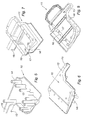
- Abb. 5 eine perspektivische Ansicht der oberen Fläche der unteren Schale ist,
- Abb. 6 eine perspektivische Ansicht der unteren Fläche der der unteren Schale ist,
- Abb. 7 eine perspektivische Ansicht der oberen Fläche der oberen Schale ist,
- Abb. 8 eine perspektivische Ansicht der unteren Fläche der oberen Schale ist,
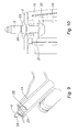
- Abb. 9 eine halbe Schnittfläche ist, die eine röhrenförmige Säule darstellt,
- Abb. 10 eine Detailansicht einer Befestigungsschraube ist, die gegen den Absatz der röhrenförmigen Säule anschlägt.
- Gemäß Abb. 1 besteht die Ölwanne aus einem Wannenkörper 1 aus synthetischem Material, der an seinem oberen Teil durch eine Verbindungsplatte 2, ebenfalls aus synthetischem Material, verschlossen ist.
- Der Wannenkörper 1 wird mittels der Befestigungsschrauben 3 am Motorblockgehäuse des Verbrennungsmotors, der hier nicht in den Abbildungen dargestellt ist, befestigt.
- Wie weiter unten im Detail beschrieben liegt die Verbindungsplatte 2 zwischen dem Wannenkörper 1 und dem Motorblockgehäuse.
- Gemäß den Abbildungen 2 und 4 erstreckt sich die Verbindungsplatte 2 auf ihrer unteren Fläche mittels eines röhrenförmigen Anschlussstückes 5, welches eine Ansaugöffnung 7 umgibt und an seinem freien Ende mit einem Filternetz 6 ausgestattet ist.
- Dieses röhrenförmige Anschlussstück 5 bildet ein Segment einer Saugleitung, die an eine nicht in den Abbildungen dargestellte Ölpumpe angeschlossen ist, um so das im Wannenkörper 1 gelagerte Öl zu den verschiedenen Teilen des Motors zu leiten, die geschmiert werden müssen.
- Die auf der Oberfläche der Verbindungsplatte 2 gebohrten Öffnungen 4 ermöglichen den Rückfluss des überschüssigen Öls in den Wannenkörper 1.
- Gemäß den Abbildungen 1 und 4 ist die Verbindungsplatte 2 auf jeder ihrer Seiten mit einer Umfangsdichtung 8, 9 ausgestattet bzw. darauf ausgegossen.
- Die Verbindungsplatte 2 ist außerdem auf ihrem Umfang mit einer Reihe Bohrungen 19, 20 ausgestattet, die das Ziel haben, den Schaft der Befestigungsschrauben aufzunehmen.
- Einige dieser Bohrungen 19 befinden sich an der Innenseite der Umfangsdichtungen 8, 9, während sich die anderen Bohrungen 20 an der Außenseite dieser Dichtungen befinden.
- Wenn der Wannenkörper 1 auf das Motorblockgehäuse aufgeschraubt wird, werden die beiden Umfangsdichtungen 8, 9 so zusammengedrückt, dass sie hier die Dichtigkeit gewährleisten.
- Gemäß den Abbildungen 2 und 3 wird der Wannenkörper 1 durch den Zusammenbau einer unteren Schale in Form eines Gefäßes 10 und einer oberen Schale 11, die auf diese an ihrem Umfang aufgeschweißt wird, gebildet.
- Die untere Schale 10 wird detaillierter in den Abbildungen 5 und 6 dargestellt.
- Die obere Schale 11 wird detaillierter in den Abbildungen 7 und 8 dargestellt.
- Gemäß den Abbildungen 2, 3, 4, 5 und 6 ist die untere Fläche der unteren Schale 10 geneigt und erstreckt sich seitlich über einen Kanal 12 bis zu einem niedrig liegenden Punkt, der mit einer durch einen Verschlussdeckel 13 verschlossenen Ablassöffnung ausgestattet ist.
- Die untere Fläche der unteren Schale 10 erstreckt sich auch nach oben durch eine Reihe röhrenförmiger, parallel verlaufender Säulen 14, deren Verwendungszweck es ist, die Befestigungsschrauben 3 des Wannenkörpers 1 aufzunehmen und sie auf dem Motorblockgehäuse einzusetzen.
- Gemäß den Abbildungen 7 und 8 hat die obere Schale 11 eine Geometrie, die diejenige der unteren Schale 10 ergänzt und sich ebenfalls seitlich durch eine Rippe 15 erstreckt, die dem Kanal 12 entspricht.
- Die obere Schale 11 ist außerdem um ihren Umfang herum mit einem Ring 16 ausgestattet, der mit Bohrungen versehen ist, die jeweils den Bohrungen 19, 20 der Verbindungsplatte 2 entsprechen, die den Schaft der Befestigungsschrauben 3 aufnehmen.
- Gemäß den Abbildungen 2 und 3 ragt ein Teil des Ringes 16 der oberen Schale 11 seitlich über die untere Schale 10 hinaus.
- Die Bohrungspaare 18, 20, die auf diesem herausragenden Teil angebracht sind und die außerhalb der Umfangsdichtungen 8, 9 liegen, nehmen die Befestigungsschrauben 3 direkt auf.
- Die anderen Bohrungspaare 17, 19 befinden sich jeweils rechts von dem oberen Ende einer röhrenförmigen Säule 14 der unteren Schale 10 innerhalb der Umfangsdichtungen 8, 9.
- Gemäß den Abbildungen 9 und 10 sind die röhrenförmigen Säulen 14 an ihrem oberen Ende mit einem Absatz 21 versehen, der als Anschlag für den Kopf 22 einer Befestigungsschraube 3 dient.
Claims (6)
- Ölwanne dazu bestimmt, mittels Schrauben auf der unteren Wandung des Motorblockgehäuses eines Verbrennungsmotors so befestigt zu werden, dass das Schmieröl gespeichert und zu den verschiedenen zu schmierenden Teilen des Motors über eine Saugleitung transportiert wird, die an eine Ölpumpe angeschlossen ist, wobei das überschüssige Öl direkt in die Ölwanne zurückläuft, dadurch gekennzeichnet, dass sie aus einem Wannenkörper (1) aus synthetischem Material besteht und an ihrem oberen Teil durch eine aus synthetischem Material hergestellte Verbindungsplatte (2) verschlossen ist, die auf ihren jeweiligen beiden Flächen mit einer darauf aufgegossenen Umfangsdichtung (8, 9) ausgestattet ist, so dass die Dichtigkeit zwischen dem Wannenkörper (1) und dem Motorblock gewährleistet ist, wobei sich die Verbindungsplatte (2) an ihrem oberen Teil durch ein röhrenförmiges Anschlussstück (5) erstreckt, das an seinem freien Ende mit einem Filternetz (6) ausgestattet ist und ein Segment der Saugleitung bildet.
- Ölwanne nach Anspruch 1, dadurch gekennzeichnet, dass der Wannenkörper (1) durch den Zusammenbau von zwei Schalen gebildet wird, nämlich eine untere Schale (10) in Form eines Gefäßes und eine obere Schale (11), die darauf verschweißt ist und die Verbindungsplatte (2) aufnimmt.
- Ölwanne nach Anspruch 2, dadurch gekennzeichnet, dass der Wannenkörper (1) ein höheres Fassungsvermögen als herkömmliche Ölwannen aus Aluminium oder aus Blech hat.
- Ölwanne nach Anspruch 2, dadurch gekennzeichnet, dass sich die untere Wandung der unteren Schale (10) nach oben durch eine Reihe von röhrenförmigen, parallel verlaufenden Säulen (14) erstreckt, die an ihrem oberen Ende einen Absatz (21) aufweisen, der einen Anschlag für den Kopf (22) der Befestigungsschraube (3) der Ölwanne auf das Motorblockgehäuse bildet.
- Ölwanne nach Anspruch 4, dadurch gekennzeichnet, dass die obere Schale (11) und die Verbindungsplatte (2) mit paarweisen Bohrungen (17, 19; 18, 20) versehen sind, um den Schaft (24) der Befestigungsschraube (3) aufzunehmen.
- Ölwanne nach Anspruch 5, dadurch gekennzeichnet, dass die Dichtungen direkt auf der Verbindungsplatte (2) integriert sind.
Applications Claiming Priority (1)
| Application Number | Priority Date | Filing Date | Title |
|---|---|---|---|
| FR0651593A FR2900687B1 (fr) | 2006-05-04 | 2006-05-04 | Carter d'huile pour moteur a combustion interne |
Publications (2)
| Publication Number | Publication Date |
|---|---|
| EP1852579A1 true EP1852579A1 (de) | 2007-11-07 |
| EP1852579B1 EP1852579B1 (de) | 2009-09-23 |
Family
ID=37546348
Family Applications (1)
| Application Number | Title | Priority Date | Filing Date |
|---|---|---|---|
| EP07107306A Not-in-force EP1852579B1 (de) | 2006-05-04 | 2007-05-02 | Ölwanne für einen Verbrennungsmotor |
Country Status (5)
| Country | Link |
|---|---|
| US (1) | US7451736B2 (de) |
| EP (1) | EP1852579B1 (de) |
| AT (1) | ATE443804T1 (de) |
| DE (1) | DE502007001565D1 (de) |
| FR (1) | FR2900687B1 (de) |
Cited By (4)
| Publication number | Priority date | Publication date | Assignee | Title |
|---|---|---|---|---|
| EP2025889A1 (de) * | 2007-08-14 | 2009-02-18 | Basf Se | Ölwanne für eine verbrennungskraftmaschine |
| DE102008028442A1 (de) | 2008-06-17 | 2009-12-24 | Rehau Ag + Co. | Ölwanne für eine Verbrennungskraftmaschine sowie Vorrichtung zur Temperierung des Motorenöls einer Verbrennungskraftmaschine |
| WO2011161339A1 (fr) * | 2010-06-24 | 2011-12-29 | Mecaplast | Carter d'huile destine a etre fixe a un bloc moteur |
| FR3027997A1 (fr) * | 2014-11-05 | 2016-05-06 | Peugeot Citroen Automobiles Sa | Carter d’huile avec boitier de liaison contenant de l’huile |
Families Citing this family (11)
| Publication number | Priority date | Publication date | Assignee | Title |
|---|---|---|---|---|
| DE202007008481U1 (de) * | 2007-06-13 | 2008-10-23 | Mann+Hummel Gmbh | Ölwanne für eine Brennkraftmaschine-Getriebe-Einheit |
| US20100229821A1 (en) * | 2009-03-13 | 2010-09-16 | Filtrauto | Plastic Structural Oil Sump with Fitted-on Bottom for a Combustion Engine and Method of Fabricating such a Sump |
| CN103291412B (zh) * | 2013-06-24 | 2016-08-10 | 潍柴动力股份有限公司 | 一种发动机及其油底壳组件 |
| FR3066555B1 (fr) * | 2017-05-16 | 2021-04-02 | Renault Sas | Agencement pour la fixation d'un carter d'huile sous le bloc moteur dans un vehicule automobile. |
| US10570788B2 (en) * | 2017-10-31 | 2020-02-25 | GM Global Technology Operations LLC | Oil pan assembly |
| JP7041531B2 (ja) * | 2018-01-26 | 2022-03-24 | 北越工業株式会社 | 作業機の防油構造 |
| US11028741B1 (en) | 2020-08-24 | 2021-06-08 | Apq Development, Llc | Oil pick-up assembly |
| USD916152S1 (en) | 2020-08-24 | 2021-04-13 | Apq Development, Llc | Compression limiter |
| USD921045S1 (en) | 2020-08-24 | 2021-06-01 | Apq Development, Llc | Oil pick-up assembly |
| US11078958B1 (en) | 2020-08-24 | 2021-08-03 | Apq Development, Llc | Compression limiter |
| CN115263490A (zh) * | 2022-06-28 | 2022-11-01 | 东风汽车集团股份有限公司 | 一种油底壳组成、发动机以及车辆 |
Citations (4)
| Publication number | Priority date | Publication date | Assignee | Title |
|---|---|---|---|---|
| FR1021184A (fr) * | 1949-06-30 | 1953-02-16 | Fiat Spa | Carteur pour moteurs à combustion interne de véhicules automobiles |
| DE19735444A1 (de) * | 1997-06-17 | 1999-01-07 | Ibs Filtran Kunststoff Metall | Ölfiltereinsatz für Ölwannen von Motoren und Getrieben |
| US6290843B1 (en) * | 2000-06-07 | 2001-09-18 | Brian Thomas Lee | Oil sump with integral filter |
| EP1526258A1 (de) * | 2003-10-21 | 2005-04-27 | Autotech Engineering, A.I.E. | Ölwanne für einen Motor mit verbesserter Ölkapazität |
-
2006
- 2006-05-04 FR FR0651593A patent/FR2900687B1/fr not_active Expired - Fee Related
-
2007
- 2007-05-02 DE DE502007001565T patent/DE502007001565D1/de active Active
- 2007-05-02 AT AT07107306T patent/ATE443804T1/de active
- 2007-05-02 EP EP07107306A patent/EP1852579B1/de not_active Not-in-force
- 2007-05-04 US US11/797,628 patent/US7451736B2/en not_active Expired - Fee Related
Patent Citations (4)
| Publication number | Priority date | Publication date | Assignee | Title |
|---|---|---|---|---|
| FR1021184A (fr) * | 1949-06-30 | 1953-02-16 | Fiat Spa | Carteur pour moteurs à combustion interne de véhicules automobiles |
| DE19735444A1 (de) * | 1997-06-17 | 1999-01-07 | Ibs Filtran Kunststoff Metall | Ölfiltereinsatz für Ölwannen von Motoren und Getrieben |
| US6290843B1 (en) * | 2000-06-07 | 2001-09-18 | Brian Thomas Lee | Oil sump with integral filter |
| EP1526258A1 (de) * | 2003-10-21 | 2005-04-27 | Autotech Engineering, A.I.E. | Ölwanne für einen Motor mit verbesserter Ölkapazität |
Cited By (5)
| Publication number | Priority date | Publication date | Assignee | Title |
|---|---|---|---|---|
| EP2025889A1 (de) * | 2007-08-14 | 2009-02-18 | Basf Se | Ölwanne für eine verbrennungskraftmaschine |
| DE102008028442A1 (de) | 2008-06-17 | 2009-12-24 | Rehau Ag + Co. | Ölwanne für eine Verbrennungskraftmaschine sowie Vorrichtung zur Temperierung des Motorenöls einer Verbrennungskraftmaschine |
| WO2011161339A1 (fr) * | 2010-06-24 | 2011-12-29 | Mecaplast | Carter d'huile destine a etre fixe a un bloc moteur |
| FR2961859A1 (fr) * | 2010-06-24 | 2011-12-30 | Mecaplast Sa | Carter d'huile destine a etre fixe a un bloc moteur |
| FR3027997A1 (fr) * | 2014-11-05 | 2016-05-06 | Peugeot Citroen Automobiles Sa | Carter d’huile avec boitier de liaison contenant de l’huile |
Also Published As
| Publication number | Publication date |
|---|---|
| FR2900687A1 (fr) | 2007-11-09 |
| ATE443804T1 (de) | 2009-10-15 |
| DE502007001565D1 (de) | 2009-11-05 |
| FR2900687B1 (fr) | 2008-07-04 |
| US20070289569A1 (en) | 2007-12-20 |
| US7451736B2 (en) | 2008-11-18 |
| EP1852579B1 (de) | 2009-09-23 |
Similar Documents
| Publication | Publication Date | Title |
|---|---|---|
| EP1852579B1 (de) | Ölwanne für einen Verbrennungsmotor | |
| EP0692292B1 (de) | Flüssigkeitsfilter | |
| DE102008038958B4 (de) | Ölwanne mit Ölfilter an Trägereinheit | |
| DE602004003483T2 (de) | Basis für verbrennungsmotor-filterpatrone | |
| DE4010946A1 (de) | Oelwanne fuer eine brennkraftmaschine | |
| EP1963655A1 (de) | Kolben für einen verbrennungsmotor und verfahren zu dessen herstellung | |
| EP2655840B1 (de) | Kolben für einen verbrennungsmotor | |
| DE102008059859A1 (de) | Getriebefiltersystem | |
| DE2810059A1 (de) | Mehrfachanordnung von motor-kompressoreinheiten fuer kuehlsysteme | |
| EP2153031B1 (de) | Ölwanne für eine brennkraftmaschine-getriebe-einheit | |
| EP1811142A2 (de) | Ölwanne, insbesondere für eine Brennkraftmaschine | |
| DE1528429A1 (de) | Membranpumpe | |
| DE10336504A1 (de) | Ölfilter | |
| DE60300287T2 (de) | Nockenwellenlagerung einer Brennkraftmaschine | |
| DE102010002790B4 (de) | An eine Brennkraftmaschine anflanschbarer Ölnebelabscheider | |
| EP0861682B1 (de) | Deckel für ein Filtergehäuse | |
| DE102010002787A1 (de) | Ölnebelabscheider mit einem Ölrückführkanal mit Siphon | |
| DE102008038878B4 (de) | Ölabscheideeinsatz und Kurbelgehäuse-Ölwannen-Einheit einer Brennkraftmaschine | |
| DE102006032795B4 (de) | Brennkraftmaschine | |
| DE10038612C1 (de) | Kurbelwelle | |
| DE19505405B4 (de) | Dichtungsvorrichtung für Wellen und Lager mit einer solchen Dichtungsvorrichtung | |
| EP1652566B1 (de) | Filtervorrichtung sowie Vorratstank für Hydrauliköl mit einer derartigen Filtervorrichtung | |
| WO2004113786A1 (de) | Druckgasbehälter | |
| DE3408015A1 (de) | Druckspruehgeraet | |
| DE102006002121A1 (de) | Trennflanschverschraubung für Turbinengehäuse mit eingegossenem Schaufelträger |
Legal Events
| Date | Code | Title | Description |
|---|---|---|---|
| PUAI | Public reference made under article 153(3) epc to a published international application that has entered the european phase |
Free format text: ORIGINAL CODE: 0009012 |
|
| AK | Designated contracting states |
Kind code of ref document: A1 Designated state(s): AT BE BG CH CY CZ DE DK EE ES FI FR GB GR HU IE IS IT LI LT LU LV MC MT NL PL PT RO SE SI SK TR |
|
| AX | Request for extension of the european patent |
Extension state: AL BA HR MK YU |
|
| 17P | Request for examination filed |
Effective date: 20071127 |
|
| 17Q | First examination report despatched |
Effective date: 20080114 |
|
| AKX | Designation fees paid |
Designated state(s): AT BE BG CH CY CZ DE DK EE ES FI FR GB GR HU IE IS IT LI LT LU LV MC MT NL PL PT RO SE SI SK TR |
|
| GRAP | Despatch of communication of intention to grant a patent |
Free format text: ORIGINAL CODE: EPIDOSNIGR1 |
|
| GRAC | Information related to communication of intention to grant a patent modified |
Free format text: ORIGINAL CODE: EPIDOSCIGR1 |
|
| RIN1 | Information on inventor provided before grant (corrected) |
Inventor name: MIGAUD, JEROME Inventor name: DE CARA, GERALD |
|
| GRAS | Grant fee paid |
Free format text: ORIGINAL CODE: EPIDOSNIGR3 |
|
| GRAA | (expected) grant |
Free format text: ORIGINAL CODE: 0009210 |
|
| AK | Designated contracting states |
Kind code of ref document: B1 Designated state(s): AT BE BG CH CY CZ DE DK EE ES FI FR GB GR HU IE IS IT LI LT LU LV MC MT NL PL PT RO SE SI SK TR |
|
| REG | Reference to a national code |
Ref country code: GB Ref legal event code: FG4D Free format text: NOT ENGLISH |
|
| REG | Reference to a national code |
Ref country code: CH Ref legal event code: EP |
|
| REG | Reference to a national code |
Ref country code: IE Ref legal event code: FG4D |
|
| REF | Corresponds to: |
Ref document number: 502007001565 Country of ref document: DE Date of ref document: 20091105 Kind code of ref document: P |
|
| PG25 | Lapsed in a contracting state [announced via postgrant information from national office to epo] |
Ref country code: LT Free format text: LAPSE BECAUSE OF FAILURE TO SUBMIT A TRANSLATION OF THE DESCRIPTION OR TO PAY THE FEE WITHIN THE PRESCRIBED TIME-LIMIT Effective date: 20090923 Ref country code: SE Free format text: LAPSE BECAUSE OF FAILURE TO SUBMIT A TRANSLATION OF THE DESCRIPTION OR TO PAY THE FEE WITHIN THE PRESCRIBED TIME-LIMIT Effective date: 20090923 Ref country code: FI Free format text: LAPSE BECAUSE OF FAILURE TO SUBMIT A TRANSLATION OF THE DESCRIPTION OR TO PAY THE FEE WITHIN THE PRESCRIBED TIME-LIMIT Effective date: 20090923 |
|
| LTIE | Lt: invalidation of european patent or patent extension |
Effective date: 20090923 |
|
| PG25 | Lapsed in a contracting state [announced via postgrant information from national office to epo] |
Ref country code: LV Free format text: LAPSE BECAUSE OF FAILURE TO SUBMIT A TRANSLATION OF THE DESCRIPTION OR TO PAY THE FEE WITHIN THE PRESCRIBED TIME-LIMIT Effective date: 20090923 Ref country code: PL Free format text: LAPSE BECAUSE OF FAILURE TO SUBMIT A TRANSLATION OF THE DESCRIPTION OR TO PAY THE FEE WITHIN THE PRESCRIBED TIME-LIMIT Effective date: 20090923 Ref country code: SI Free format text: LAPSE BECAUSE OF FAILURE TO SUBMIT A TRANSLATION OF THE DESCRIPTION OR TO PAY THE FEE WITHIN THE PRESCRIBED TIME-LIMIT Effective date: 20090923 |
|
| NLV1 | Nl: lapsed or annulled due to failure to fulfill the requirements of art. 29p and 29m of the patents act | ||
| PG25 | Lapsed in a contracting state [announced via postgrant information from national office to epo] |
Ref country code: CY Free format text: LAPSE BECAUSE OF FAILURE TO SUBMIT A TRANSLATION OF THE DESCRIPTION OR TO PAY THE FEE WITHIN THE PRESCRIBED TIME-LIMIT Effective date: 20090923 |
|
| REG | Reference to a national code |
Ref country code: IE Ref legal event code: FD4D |
|
| PG25 | Lapsed in a contracting state [announced via postgrant information from national office to epo] |
Ref country code: EE Free format text: LAPSE BECAUSE OF FAILURE TO SUBMIT A TRANSLATION OF THE DESCRIPTION OR TO PAY THE FEE WITHIN THE PRESCRIBED TIME-LIMIT Effective date: 20090923 Ref country code: RO Free format text: LAPSE BECAUSE OF FAILURE TO SUBMIT A TRANSLATION OF THE DESCRIPTION OR TO PAY THE FEE WITHIN THE PRESCRIBED TIME-LIMIT Effective date: 20090923 Ref country code: ES Free format text: LAPSE BECAUSE OF FAILURE TO SUBMIT A TRANSLATION OF THE DESCRIPTION OR TO PAY THE FEE WITHIN THE PRESCRIBED TIME-LIMIT Effective date: 20100103 Ref country code: PT Free format text: LAPSE BECAUSE OF FAILURE TO SUBMIT A TRANSLATION OF THE DESCRIPTION OR TO PAY THE FEE WITHIN THE PRESCRIBED TIME-LIMIT Effective date: 20100125 Ref country code: IE Free format text: LAPSE BECAUSE OF FAILURE TO SUBMIT A TRANSLATION OF THE DESCRIPTION OR TO PAY THE FEE WITHIN THE PRESCRIBED TIME-LIMIT Effective date: 20090923 Ref country code: IS Free format text: LAPSE BECAUSE OF FAILURE TO SUBMIT A TRANSLATION OF THE DESCRIPTION OR TO PAY THE FEE WITHIN THE PRESCRIBED TIME-LIMIT Effective date: 20100123 Ref country code: CZ Free format text: LAPSE BECAUSE OF FAILURE TO SUBMIT A TRANSLATION OF THE DESCRIPTION OR TO PAY THE FEE WITHIN THE PRESCRIBED TIME-LIMIT Effective date: 20090923 |
|
| PG25 | Lapsed in a contracting state [announced via postgrant information from national office to epo] |
Ref country code: SK Free format text: LAPSE BECAUSE OF FAILURE TO SUBMIT A TRANSLATION OF THE DESCRIPTION OR TO PAY THE FEE WITHIN THE PRESCRIBED TIME-LIMIT Effective date: 20090923 |
|
| PG25 | Lapsed in a contracting state [announced via postgrant information from national office to epo] |
Ref country code: NL Free format text: LAPSE BECAUSE OF FAILURE TO SUBMIT A TRANSLATION OF THE DESCRIPTION OR TO PAY THE FEE WITHIN THE PRESCRIBED TIME-LIMIT Effective date: 20090923 Ref country code: DK Free format text: LAPSE BECAUSE OF FAILURE TO SUBMIT A TRANSLATION OF THE DESCRIPTION OR TO PAY THE FEE WITHIN THE PRESCRIBED TIME-LIMIT Effective date: 20090923 |
|
| PLBE | No opposition filed within time limit |
Free format text: ORIGINAL CODE: 0009261 |
|
| STAA | Information on the status of an ep patent application or granted ep patent |
Free format text: STATUS: NO OPPOSITION FILED WITHIN TIME LIMIT |
|
| 26N | No opposition filed |
Effective date: 20100624 |
|
| PG25 | Lapsed in a contracting state [announced via postgrant information from national office to epo] |
Ref country code: GR Free format text: LAPSE BECAUSE OF FAILURE TO SUBMIT A TRANSLATION OF THE DESCRIPTION OR TO PAY THE FEE WITHIN THE PRESCRIBED TIME-LIMIT Effective date: 20091224 |
|
| BERE | Be: lapsed |
Owner name: MANN+HUMMEL G.M.B.H. Effective date: 20100531 |
|
| PG25 | Lapsed in a contracting state [announced via postgrant information from national office to epo] |
Ref country code: MC Free format text: LAPSE BECAUSE OF NON-PAYMENT OF DUE FEES Effective date: 20100531 |
|
| REG | Reference to a national code |
Ref country code: FR Ref legal event code: ST Effective date: 20110131 |
|
| PG25 | Lapsed in a contracting state [announced via postgrant information from national office to epo] |
Ref country code: IT Free format text: LAPSE BECAUSE OF FAILURE TO SUBMIT A TRANSLATION OF THE DESCRIPTION OR TO PAY THE FEE WITHIN THE PRESCRIBED TIME-LIMIT Effective date: 20090923 Ref country code: BE Free format text: LAPSE BECAUSE OF NON-PAYMENT OF DUE FEES Effective date: 20100531 |
|
| PG25 | Lapsed in a contracting state [announced via postgrant information from national office to epo] |
Ref country code: MT Free format text: LAPSE BECAUSE OF FAILURE TO SUBMIT A TRANSLATION OF THE DESCRIPTION OR TO PAY THE FEE WITHIN THE PRESCRIBED TIME-LIMIT Effective date: 20090923 |
|
| PG25 | Lapsed in a contracting state [announced via postgrant information from national office to epo] |
Ref country code: FR Free format text: LAPSE BECAUSE OF NON-PAYMENT OF DUE FEES Effective date: 20100531 |
|
| REG | Reference to a national code |
Ref country code: CH Ref legal event code: PL |
|
| GBPC | Gb: european patent ceased through non-payment of renewal fee |
Effective date: 20110502 |
|
| PG25 | Lapsed in a contracting state [announced via postgrant information from national office to epo] |
Ref country code: LI Free format text: LAPSE BECAUSE OF NON-PAYMENT OF DUE FEES Effective date: 20110531 Ref country code: CH Free format text: LAPSE BECAUSE OF NON-PAYMENT OF DUE FEES Effective date: 20110531 |
|
| PG25 | Lapsed in a contracting state [announced via postgrant information from national office to epo] |
Ref country code: GB Free format text: LAPSE BECAUSE OF NON-PAYMENT OF DUE FEES Effective date: 20110502 |
|
| PG25 | Lapsed in a contracting state [announced via postgrant information from national office to epo] |
Ref country code: HU Free format text: LAPSE BECAUSE OF FAILURE TO SUBMIT A TRANSLATION OF THE DESCRIPTION OR TO PAY THE FEE WITHIN THE PRESCRIBED TIME-LIMIT Effective date: 20100324 Ref country code: LU Free format text: LAPSE BECAUSE OF NON-PAYMENT OF DUE FEES Effective date: 20100502 Ref country code: BG Free format text: LAPSE BECAUSE OF FAILURE TO SUBMIT A TRANSLATION OF THE DESCRIPTION OR TO PAY THE FEE WITHIN THE PRESCRIBED TIME-LIMIT Effective date: 20090923 |
|
| PG25 | Lapsed in a contracting state [announced via postgrant information from national office to epo] |
Ref country code: TR Free format text: LAPSE BECAUSE OF FAILURE TO SUBMIT A TRANSLATION OF THE DESCRIPTION OR TO PAY THE FEE WITHIN THE PRESCRIBED TIME-LIMIT Effective date: 20090923 |
|
| REG | Reference to a national code |
Ref country code: AT Ref legal event code: MM01 Ref document number: 443804 Country of ref document: AT Kind code of ref document: T Effective date: 20120502 |
|
| PG25 | Lapsed in a contracting state [announced via postgrant information from national office to epo] |
Ref country code: AT Free format text: LAPSE BECAUSE OF NON-PAYMENT OF DUE FEES Effective date: 20120502 |
|
| REG | Reference to a national code |
Ref country code: DE Ref legal event code: R081 Ref document number: 502007001565 Country of ref document: DE Owner name: MANN+HUMMEL GMBH, DE Free format text: FORMER OWNER: MANN + HUMMEL GMBH, 71638 LUDWIGSBURG, DE |
|
| PGFP | Annual fee paid to national office [announced via postgrant information from national office to epo] |
Ref country code: DE Payment date: 20190521 Year of fee payment: 13 |
|
| REG | Reference to a national code |
Ref country code: DE Ref legal event code: R119 Ref document number: 502007001565 Country of ref document: DE |
|
| PG25 | Lapsed in a contracting state [announced via postgrant information from national office to epo] |
Ref country code: DE Free format text: LAPSE BECAUSE OF NON-PAYMENT OF DUE FEES Effective date: 20201201 |