EP1852591A2 - Vorrichtung zur Abschätzung des Triebwerkschubs - Google Patents
Vorrichtung zur Abschätzung des Triebwerkschubs Download PDFInfo
- Publication number
- EP1852591A2 EP1852591A2 EP07103520A EP07103520A EP1852591A2 EP 1852591 A2 EP1852591 A2 EP 1852591A2 EP 07103520 A EP07103520 A EP 07103520A EP 07103520 A EP07103520 A EP 07103520A EP 1852591 A2 EP1852591 A2 EP 1852591A2
- Authority
- EP
- European Patent Office
- Prior art keywords
- engine
- thrust
- linear
- state
- estimator
- Prior art date
- Legal status (The legal status is an assumption and is not a legal conclusion. Google has not performed a legal analysis and makes no representation as to the accuracy of the status listed.)
- Withdrawn
Links
Images

Classifications
-
- F—MECHANICAL ENGINEERING; LIGHTING; HEATING; WEAPONS; BLASTING
- F02—COMBUSTION ENGINES; HOT-GAS OR COMBUSTION-PRODUCT ENGINE PLANTS
- F02C—GAS-TURBINE PLANTS; AIR INTAKES FOR JET-PROPULSION PLANTS; CONTROLLING FUEL SUPPLY IN AIR-BREATHING JET-PROPULSION PLANTS
- F02C9/00—Controlling gas-turbine plants; Controlling fuel supply in air- breathing jet-propulsion plants
- F02C9/26—Control of fuel supply
- F02C9/28—Regulating systems responsive to plant or ambient parameters, e.g. temperature, pressure, rotor speed
-
- F—MECHANICAL ENGINEERING; LIGHTING; HEATING; WEAPONS; BLASTING
- F05—INDEXING SCHEMES RELATING TO ENGINES OR PUMPS IN VARIOUS SUBCLASSES OF CLASSES F01-F04
- F05D—INDEXING SCHEME FOR ASPECTS RELATING TO NON-POSITIVE-DISPLACEMENT MACHINES OR ENGINES, GAS-TURBINES OR JET-PROPULSION PLANTS
- F05D2270/00—Control
- F05D2270/01—Purpose of the control system
- F05D2270/05—Purpose of the control system to affect the output of the engine
- F05D2270/051—Thrust
-
- F—MECHANICAL ENGINEERING; LIGHTING; HEATING; WEAPONS; BLASTING
- F05—INDEXING SCHEMES RELATING TO ENGINES OR PUMPS IN VARIOUS SUBCLASSES OF CLASSES F01-F04
- F05D—INDEXING SCHEME FOR ASPECTS RELATING TO NON-POSITIVE-DISPLACEMENT MACHINES OR ENGINES, GAS-TURBINES OR JET-PROPULSION PLANTS
- F05D2270/00—Control
- F05D2270/70—Type of control algorithm
- F05D2270/71—Type of control algorithm synthesized, i.e. parameter computed by a mathematical model
Definitions
- This invention relates generally to aircraft engines and more particularly, to methods and apparatus for estimating engine thrust.
- Engine thrust cannot be measured directly in flight. Since engine thrust cannot be measured, known engines are indirectly controlled via a measurable parameter (such as fan speed or engine pressure ratio, which are good indicators of thrust) in order to meet a specific thrust demand. Each of the available known thrust indicators may, however, be subject to errors due to random variations in engine-to-engine component quality, deterioration, engine sensor errors and actuator position errors. On the other hand, if engine thrust could be estimated accurately, then engine thrust demands could be met precisely through direct thrust control.
- a measurable parameter such as fan speed or engine pressure ratio, which are good indicators of thrust
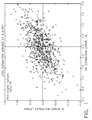
- engine thrust-HP turbine temperature distribution is Bivariate Normal
- a fan speed bias on thrust may be identified and added to the nominal control schedules used for all engines, such that the lowest 2-sigma thrust engine may meet, or exceed, rated thrust.
- higher thrust engines can be over-boosted by typically 2-4% in thrust, for example, and operated typcially at increased turbine temperatures such as, for example 120°F on commercial engines and/or 160°F on military engines, hotter than nominal.
- Engine specific fuel consumption and engine life will both be affected adversely by the over-boost.
- Algorithms for tracking engine parameters are sometimes referred to herein as filters, and may provide estimates of engine component flows and efficiencies. At least some known filters do not consider information from more than one operating point simultaneously, and as such, the number of parameters estimated is equal to the number of sensors. Since the number of sensors is usually less than the number of parameters to be estimated, such filters combine the effect of several parameters into a few parameters, which inhibits individually tracking each parameter.
- Known filters include for example steady-state tracking filters or dynamic tracking filters which use for example, Kalman filters, and/or least-squares estimators.
- Known nonlinear estimation filters include neural networks and/or fuzzy rule-based systems.
- a method for estimating engine thrust includes obtaining information about an initial dynamic state of the engine and updating the information about the initial dynamic state of the engine to reflect a second dynamic state of the engine.
- the method also includes generating engine thrust estimates, wherein the thrust estimates facilitate implementing direct thrust control.
- an apparatus for estimating engine thrust includes a processor coupled to the engine for receiving input from the plurality of sensors.
- the processor is programmed to obtain information from the engine during a first operating condition and update information from the engine during a second operating condition.
- the process is also programmed to generate engine thrust estimates utilizing the obtained information and the updated information and implementing direct thrust control.
- a system for controlling a gas turbine engine includes at least one model capable of representing a system behavior and at least one thrust estimator capable of estimating engine thrust.
- thrust estimators use the available engine to estimate engine thrust and permit engine operation at estimated thrust rather than at a thrust indicator, such as fan speed or engine pressure ratio. It is possible to achieve thrust estimation errors which are substantially smaller than the thrust uncertainties associated with operation at fan speed or engine pressure ratio. This can lead to a substantial reduction in the over-boost and over-temperatures of conventional engine operation.
- a Kalman Filter is an optimal estimation algorithm that accurately estimates system "states", in the presence of modeling uncertainties and output measurement errors.
- a Kalman Filter has been derived for optimal thrust estimation using the engine thrust (Fn) and HP Turbine Inlet Temperature (T41) as system states.
- Partial derivative matrices are generated from a nonlinear, physics based engine model (such as a Cycle Workstation or CWS model), with rotor speeds n 1 and n 2 as system states.
- the speed states must be then replaced by Fn and T41 which are the states to be estimated. This is achieved by a row-column transformation between the states (n 1 and n 2 ) and the output rows for Fn and T41.
- Fn and T41 dynamics were then added by differentiating rows for n 1 and n 2 , equating the result to the existing n 1 dot and n 2 dot equations from the ⁇ equation, and solving for Fndot and T41 dot.
- equation (2) is typically a matrix equation containing 10-15 rows and 50-60 columns.
- Equation (2) can then be used in a Kalman Filter approach for estimating Fn and T41.
- the estimation process requires two updates during each time step.
- the first update represents a measurement update which utilizes the changes in the output vector Y from the previous time step.
- X t is the state estimate from the previous time step
- U m is the change in the control vector from the previous time step
- Y m is the change in the output vector from the previous time step
- X m is the new state estimate.
- It also includes an update of the state error covariance matrix for use in the next time update: PP I - M * C * P
- the thrust estimator has been tested on a model of the JSF Engine in the CTOL operating mode.
- Initial testing has included linear simulations for both steady-state and transient operation at sea level static operating conditions.
- the steady-state testing has involved a Monte Carlo study of 800 random engines with eighteen component performance parameters (flows, efficiencies, parasitic flows, etc.) assumed to be normally distributed, seven control inputs (cepr, lepr, vabi, etc.) with position errors assumed to be normally distributed, and eleven engine sensors (speeds, temperatures, and pressures) assumed to be normally distributed. Component deterioration was assumed to be uniformly distributed from no deterioration (new engine) to 100% (fully deteriorated).
- Figure 1 illustrates exemplary results of the Monte Carlo study.
- Fan speed demand has been biased by the 2-sigma variation in thrust at fan speed ( ⁇ 3%) in order to meet, or exceed, nominal thrust on 98.5% of the 800 engine sample (all but 12 engines).
- the hottest 98.5% engine would be running 175 °F hotter than nominal.
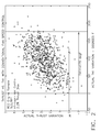
- Figure 3 illustrates a similar plot of actual thrust vs. actual T41 for an 800 engine sample in which fan speed has been replaced by estimated thrust.
- the Estimator reduces the thrust uncertainty from ⁇ 3% at fan speed to ⁇ 0.65% at estimated thrust. This reduces the bias necessary to assure that 98.5% of the engine population meets or exceeds nominal thrust.
- Maximum T41 will be reduced accordingly to 138 °F (a reduction of about 37°F or 21%).
- Transient testing used the linear engine model (LEM) to simulate a deteriorated engine transient from IRP to idle.
- the thrust estimator (which is a linear estimator) tracked both thrust and T41 over the complete transient. Thrust and temperature estimation errors were extremely small indicating that the linear implementation was correct.
Landscapes
- Engineering & Computer Science (AREA)
- Chemical & Material Sciences (AREA)
- Combustion & Propulsion (AREA)
- Mechanical Engineering (AREA)
- General Engineering & Computer Science (AREA)
- Feedback Control In General (AREA)
- Combined Controls Of Internal Combustion Engines (AREA)
Applications Claiming Priority (1)
| Application Number | Priority Date | Filing Date | Title |
|---|---|---|---|
| US11/381,821 US20070260424A1 (en) | 2006-05-05 | 2006-05-05 | Methods and apparatus for estimating engine thrust |
Publications (2)
| Publication Number | Publication Date |
|---|---|
| EP1852591A2 true EP1852591A2 (de) | 2007-11-07 |
| EP1852591A3 EP1852591A3 (de) | 2012-12-26 |
Family
ID=38179505
Family Applications (1)
| Application Number | Title | Priority Date | Filing Date |
|---|---|---|---|
| EP07103520A Withdrawn EP1852591A3 (de) | 2006-05-05 | 2007-03-05 | Vorrichtung zur Abschätzung des Triebwerkschubs |
Country Status (3)
| Country | Link |
|---|---|
| US (1) | US20070260424A1 (de) |
| EP (1) | EP1852591A3 (de) |
| JP (1) | JP2007298026A (de) |
Cited By (1)
| Publication number | Priority date | Publication date | Assignee | Title |
|---|---|---|---|---|
| CN108573116A (zh) * | 2018-05-11 | 2018-09-25 | 南京航空航天大学 | 一种基于长短时记忆网络的航空发动机过渡态推力估计算法 |
Families Citing this family (10)
| Publication number | Priority date | Publication date | Assignee | Title |
|---|---|---|---|---|
| US7505844B2 (en) * | 2005-11-18 | 2009-03-17 | General Electric Company | Model-based iterative estimation of gas turbine engine component qualities |
| EP1837506B1 (de) * | 2006-03-24 | 2013-08-28 | Rolls-Royce plc | Verfahren zur Überwachung des Schubs eines Gasturbinentriebwerks |
| WO2009045218A1 (en) | 2007-10-04 | 2009-04-09 | Donovan John J | A video surveillance, storage, and alerting system having network management, hierarchical data storage, video tip processing, and vehicle plate analysis |
| US8013738B2 (en) | 2007-10-04 | 2011-09-06 | Kd Secure, Llc | Hierarchical storage manager (HSM) for intelligent storage of large volumes of data |
| US7861578B2 (en) | 2008-07-29 | 2011-01-04 | General Electric Company | Methods and systems for estimating operating parameters of an engine |
| US8380473B2 (en) * | 2009-06-13 | 2013-02-19 | Eric T. Falangas | Method of modeling dynamic characteristics of a flight vehicle |
| US9115662B1 (en) * | 2009-07-10 | 2015-08-25 | The Boeing Company | Health-adaptive reaction control system |
| JP6060812B2 (ja) * | 2013-05-17 | 2017-01-18 | 株式会社デンソー | エンジン制御装置 |
| US10746253B2 (en) | 2015-08-20 | 2020-08-18 | Sikorsky Aircraft Corporation | Vibration damping device for an elongated member |
| US20170328567A1 (en) * | 2016-05-11 | 2017-11-16 | United Technologies Corporation | Multivariable fuel control and estimator (mfce) for preventing combustor blowout |
Family Cites Families (20)
| Publication number | Priority date | Publication date | Assignee | Title |
|---|---|---|---|---|
| US3834222A (en) * | 1972-01-31 | 1974-09-10 | Control Data Canada | Methods and apparatus for determining the thrust of a jet engine |
| US4275557A (en) * | 1978-01-25 | 1981-06-30 | General Electric Company | Method and apparatus for controlling thrust in a gas turbine engine |
| US4313167A (en) * | 1979-07-27 | 1982-01-26 | General Electric Company | Thrust control system for a gas turbine engine |
| US5031102A (en) * | 1979-12-03 | 1991-07-09 | The Boeing Company | Method and apparatus for aircraft pitch and thrust axes control |
| GB2174761B (en) * | 1985-05-03 | 1989-09-06 | Gen Electric | High mach number unducted fan engine |
| GB2211965B (en) * | 1987-10-31 | 1992-05-06 | Rolls Royce Plc | Data processing systems |
| EP0458453B1 (de) * | 1990-04-21 | 1995-03-08 | ROLLS-ROYCE plc | Schubmessung für Gasturbinenmotor |
| US5299765A (en) * | 1991-12-23 | 1994-04-05 | The Boeing Company | Apparatus and methods for controlling aircraft thrust during a climb |
| US5303545A (en) * | 1992-10-05 | 1994-04-19 | United Technologies Corporation | Pressure based close loop thrust control in a turbofan engine |
| US5657949A (en) * | 1995-05-10 | 1997-08-19 | The Boeing Company | Method and apparatus for providing a dynamic thrust asymmetry rudder compensation command with no direct thrust measurement |
| US6539783B1 (en) * | 1998-12-28 | 2003-04-01 | General Electric Co. | Methods and apparatus for estimating engine health |
| US6502085B1 (en) * | 1999-12-18 | 2002-12-31 | General Electric Company | Methods and systems for estimating engine faults |
| US6459963B1 (en) * | 2000-07-31 | 2002-10-01 | General Electric Company | Methods and apparatus for trimming engine control systems |
| US6466858B1 (en) * | 2000-11-02 | 2002-10-15 | General Electric Company | Methods and apparatus for monitoring gas turbine engine operation |
| US6681558B2 (en) * | 2001-03-26 | 2004-01-27 | General Electric Company | Method of increasing engine temperature limit margins |
| US7003426B2 (en) * | 2002-10-04 | 2006-02-21 | General Electric Company | Method and system for detecting precursors to compressor stall and surge |
| US6823675B2 (en) * | 2002-11-13 | 2004-11-30 | General Electric Company | Adaptive model-based control systems and methods for controlling a gas turbine |
| FR2854128B1 (fr) * | 2003-04-22 | 2006-04-07 | Airbus France | Indicateur de pilotage pour un aeronef, en particulier un avion de transport, destine a fournir la poussee engendree par au moins un moteur de l'aeronef |
| US7177785B2 (en) * | 2003-08-22 | 2007-02-13 | Honeywell International, Inc. | Systems and methods for improved aircraft performance predictions |
| JP4555562B2 (ja) * | 2003-12-09 | 2010-10-06 | ゼネラル・エレクトリック・カンパニイ | 航空機用ガスタービンのモデル予測制御のための方法及び装置 |
-
2006
- 2006-05-05 US US11/381,821 patent/US20070260424A1/en not_active Abandoned
-
2007
- 2007-03-05 EP EP07103520A patent/EP1852591A3/de not_active Withdrawn
- 2007-03-05 JP JP2007054049A patent/JP2007298026A/ja active Pending
Cited By (2)
| Publication number | Priority date | Publication date | Assignee | Title |
|---|---|---|---|---|
| CN108573116A (zh) * | 2018-05-11 | 2018-09-25 | 南京航空航天大学 | 一种基于长短时记忆网络的航空发动机过渡态推力估计算法 |
| CN108573116B (zh) * | 2018-05-11 | 2020-06-09 | 南京航空航天大学 | 一种基于长短时记忆网络的航空发动机过渡态推力估计方法 |
Also Published As
| Publication number | Publication date |
|---|---|
| US20070260424A1 (en) | 2007-11-08 |
| EP1852591A3 (de) | 2012-12-26 |
| JP2007298026A (ja) | 2007-11-15 |
Similar Documents
| Publication | Publication Date | Title |
|---|---|---|
| EP1852591A2 (de) | Vorrichtung zur Abschätzung des Triebwerkschubs | |
| EP0858017B1 (de) | Mittel und Methode zur Überwachung der Leistung eines Systems | |
| US7020595B1 (en) | Methods and apparatus for model based diagnostics | |
| US6539783B1 (en) | Methods and apparatus for estimating engine health | |
| US7904282B2 (en) | Method and system for fault accommodation of machines | |
| Li et al. | A method to improve the robustness of gas turbine gas-path fault diagnosis against sensor faults | |
| US7058556B2 (en) | Adaptive aero-thermodynamic engine model | |
| US6466858B1 (en) | Methods and apparatus for monitoring gas turbine engine operation | |
| Volponi et al. | The use of Kalman filter and neural network methodologies in gas turbine performance diagnostics: a comparative study | |
| US6909960B2 (en) | Method for performing gas turbine performance diagnostics | |
| CN1966955B (zh) | 燃气涡轮发动机部件评价质量参量的系统 | |
| CN110579962B (zh) | 基于神经网络的涡扇发动机推力预测方法及控制器 | |
| EP3316051A1 (de) | Adaptives modellreferenzsteuergerät | |
| US20040030417A1 (en) | Tracking systems for detecting sensor errors | |
| Simon et al. | Aircraft turbofan engine health estimation using constrained Kalman filtering | |
| CA2667154A1 (en) | Methods and systems for estimating operating parameters of an engine | |
| Simon et al. | Benchmarking gas path diagnostic methods: a public approach | |
| CN107045575A (zh) | 基于自调整维纳模型的航空发动机性能模型建模方法 | |
| CN110647052B (zh) | 一种变循环发动机模式切换自适应身份证模型构建方法 | |
| Kobayashi et al. | Hybrid Kalman filter approach for aircraft engine in-flight diagnostics: Sensor fault detection case | |
| Huang et al. | Gas path deterioration observation based on stochastic dynamics for reliability assessment of aeroengines | |
| US6931857B2 (en) | Rotor inlet temperature control for turbo machine | |
| Zou et al. | An online gas path fault diagnosis for aircraft engine transient behavior using iB-EKF algorithm | |
| Kong et al. | Study on condition monitoring of 2-spool turbofan engine using non-linear GPA (gas path analysis) method and genetic algorithms | |
| Rootliep et al. | Evolutionary algorithm for enhanced gas path analysis in turbofan engines |
Legal Events
| Date | Code | Title | Description |
|---|---|---|---|
| PUAI | Public reference made under article 153(3) epc to a published international application that has entered the european phase |
Free format text: ORIGINAL CODE: 0009012 |
|
| AK | Designated contracting states |
Kind code of ref document: A2 Designated state(s): AT BE BG CH CY CZ DE DK EE ES FI FR GB GR HU IE IS IT LI LT LU LV MC MT NL PL PT RO SE SI SK TR |
|
| AX | Request for extension of the european patent |
Extension state: AL BA HR MK YU |
|
| PUAL | Search report despatched |
Free format text: ORIGINAL CODE: 0009013 |
|
| AK | Designated contracting states |
Kind code of ref document: A3 Designated state(s): AT BE BG CH CY CZ DE DK EE ES FI FR GB GR HU IE IS IT LI LT LU LV MC MT NL PL PT RO SE SI SK TR |
|
| AX | Request for extension of the european patent |
Extension state: AL BA HR MK RS |
|
| RIC1 | Information provided on ipc code assigned before grant |
Ipc: F02C 9/28 20060101AFI20121122BHEP |
|
| AKY | No designation fees paid | ||
| REG | Reference to a national code |
Ref country code: DE Ref legal event code: R108 |
|
| REG | Reference to a national code |
Ref country code: DE Ref legal event code: R108 Effective date: 20130904 |
|
| STAA | Information on the status of an ep patent application or granted ep patent |
Free format text: STATUS: THE APPLICATION IS DEEMED TO BE WITHDRAWN |
|
| 18D | Application deemed to be withdrawn |
Effective date: 20130627 |