EP1852607A1 - Taumelscheibenkompressor mit veränderlicher Förderleistung - Google Patents
Taumelscheibenkompressor mit veränderlicher Förderleistung Download PDFInfo
- Publication number
- EP1852607A1 EP1852607A1 EP07008652A EP07008652A EP1852607A1 EP 1852607 A1 EP1852607 A1 EP 1852607A1 EP 07008652 A EP07008652 A EP 07008652A EP 07008652 A EP07008652 A EP 07008652A EP 1852607 A1 EP1852607 A1 EP 1852607A1
- Authority
- EP
- European Patent Office
- Prior art keywords
- refrigerant
- check valve
- swash plate
- chamber
- discharge
- Prior art date
- Legal status (The legal status is an assumption and is not a legal conclusion. Google has not performed a legal analysis and makes no representation as to the accuracy of the status listed.)
- Granted
Links
Images

Classifications
-
- F—MECHANICAL ENGINEERING; LIGHTING; HEATING; WEAPONS; BLASTING
- F04—POSITIVE - DISPLACEMENT MACHINES FOR LIQUIDS; PUMPS FOR LIQUIDS OR ELASTIC FLUIDS
- F04B—POSITIVE-DISPLACEMENT MACHINES FOR LIQUIDS; PUMPS
- F04B25/00—Multi-stage pumps
- F04B25/04—Multi-stage pumps having cylinders coaxial with, or parallel or inclined to, main shaft axis
-
- F—MECHANICAL ENGINEERING; LIGHTING; HEATING; WEAPONS; BLASTING
- F04—POSITIVE - DISPLACEMENT MACHINES FOR LIQUIDS; PUMPS FOR LIQUIDS OR ELASTIC FLUIDS
- F04B—POSITIVE-DISPLACEMENT MACHINES FOR LIQUIDS; PUMPS
- F04B27/00—Multi-cylinder pumps specially adapted for elastic fluids and characterised by number or arrangement of cylinders
- F04B27/08—Multi-cylinder pumps specially adapted for elastic fluids and characterised by number or arrangement of cylinders having cylinders coaxial with, or parallel or inclined to, main shaft axis
- F04B27/10—Multi-cylinder pumps specially adapted for elastic fluids and characterised by number or arrangement of cylinders having cylinders coaxial with, or parallel or inclined to, main shaft axis having stationary cylinders
- F04B27/1036—Component parts, details, e.g. sealings, lubrication
- F04B27/1081—Casings, housings
-
- F—MECHANICAL ENGINEERING; LIGHTING; HEATING; WEAPONS; BLASTING
- F04—POSITIVE - DISPLACEMENT MACHINES FOR LIQUIDS; PUMPS FOR LIQUIDS OR ELASTIC FLUIDS
- F04B—POSITIVE-DISPLACEMENT MACHINES FOR LIQUIDS; PUMPS
- F04B27/00—Multi-cylinder pumps specially adapted for elastic fluids and characterised by number or arrangement of cylinders
- F04B27/08—Multi-cylinder pumps specially adapted for elastic fluids and characterised by number or arrangement of cylinders having cylinders coaxial with, or parallel or inclined to, main shaft axis
-
- F—MECHANICAL ENGINEERING; LIGHTING; HEATING; WEAPONS; BLASTING
- F04—POSITIVE - DISPLACEMENT MACHINES FOR LIQUIDS; PUMPS FOR LIQUIDS OR ELASTIC FLUIDS
- F04B—POSITIVE-DISPLACEMENT MACHINES FOR LIQUIDS; PUMPS
- F04B39/00—Component parts, details, or accessories, of pumps or pumping systems specially adapted for elastic fluids, not otherwise provided for in, or of interest apart from, groups F04B25/00 - F04B37/00
- F04B39/0027—Pulsation and noise damping means
- F04B39/0055—Pulsation and noise damping means with a special shape of fluid passage, e.g. bends, throttles, diameter changes, pipes
- F04B39/0061—Pulsation and noise damping means with a special shape of fluid passage, e.g. bends, throttles, diameter changes, pipes using muffler volumes
-
- F—MECHANICAL ENGINEERING; LIGHTING; HEATING; WEAPONS; BLASTING
- F04—POSITIVE - DISPLACEMENT MACHINES FOR LIQUIDS; PUMPS FOR LIQUIDS OR ELASTIC FLUIDS
- F04B—POSITIVE-DISPLACEMENT MACHINES FOR LIQUIDS; PUMPS
- F04B39/00—Component parts, details, or accessories, of pumps or pumping systems specially adapted for elastic fluids, not otherwise provided for in, or of interest apart from, groups F04B25/00 - F04B37/00
- F04B39/10—Adaptations or arrangements of distribution members
-
- F—MECHANICAL ENGINEERING; LIGHTING; HEATING; WEAPONS; BLASTING
- F04—POSITIVE - DISPLACEMENT MACHINES FOR LIQUIDS; PUMPS FOR LIQUIDS OR ELASTIC FLUIDS
- F04B—POSITIVE-DISPLACEMENT MACHINES FOR LIQUIDS; PUMPS
- F04B49/00—Control, e.g. of pump delivery, or pump pressure of, or safety measures for, machines, pumps, or pumping installations, not otherwise provided for, or of interest apart from, groups F04B1/00 - F04B47/00
- F04B49/22—Control, e.g. of pump delivery, or pump pressure of, or safety measures for, machines, pumps, or pumping installations, not otherwise provided for, or of interest apart from, groups F04B1/00 - F04B47/00 by means of valves
- F04B49/225—Control, e.g. of pump delivery, or pump pressure of, or safety measures for, machines, pumps, or pumping installations, not otherwise provided for, or of interest apart from, groups F04B1/00 - F04B47/00 by means of valves with throttling valves or valves varying the pump inlet opening or the outlet opening
-
- F—MECHANICAL ENGINEERING; LIGHTING; HEATING; WEAPONS; BLASTING
- F04—POSITIVE - DISPLACEMENT MACHINES FOR LIQUIDS; PUMPS FOR LIQUIDS OR ELASTIC FLUIDS
- F04B—POSITIVE-DISPLACEMENT MACHINES FOR LIQUIDS; PUMPS
- F04B27/00—Multi-cylinder pumps specially adapted for elastic fluids and characterised by number or arrangement of cylinders
- F04B27/08—Multi-cylinder pumps specially adapted for elastic fluids and characterised by number or arrangement of cylinders having cylinders coaxial with, or parallel or inclined to, main shaft axis
- F04B27/14—Control
- F04B27/16—Control of pumps with stationary cylinders
- F04B27/18—Control of pumps with stationary cylinders by varying the relative positions of a swash plate and a cylinder block
- F04B27/1804—Controlled by crankcase pressure
- F04B2027/1863—Controlled by crankcase pressure with an auxiliary valve, controlled by
- F04B2027/1872—Discharge pressure
Definitions
- the present invention relates to a variable capacity swash plate type compressor, and more particularly, to a variable capacity swash plate type compressor, in which a check valve for circulating refrigerant inside a compressor and preventing a backflow of the refrigerant when an air conditioner is turned off is mounted on a side of a discharge muffler chamber in a cover type so that the discharge muffler chamber is formed by the check valve, thereby reducing the number of components, the number of work processes, and a pulsating pressure (pulsating noise) of discharged refrigerant, allowing that the check valve is mounted at the center of a discharge chamber without any increase in size of the compressor, preventing an overlapping phenomenon of a pulsating pressure waveform of a high-pressure refrigerant at the time of discharge since the check valve is located at the center of the discharge chamber, and preventing a separation of the check valve by fixing the check valve in the discharge chamber via a retainer.
- a compressor constituting an air conditioner for an automobile is operated through the steps of selectively receiving driving power from a power source by mean of a restricting action of an electromagnetic clutch, inhaling refrigerant gas from an evaporator thereto, compressing the refrigerant gas by a straight reciprocating motion of pistons, and discharging it toward a condenser.
- Such a compressor is classified into various kinds according to compression methods and structures, and among the compressors of the various kinds a variable capacitance compressor has been widely used which can vary a compression volume.
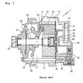
- FIG. 1 is a sectional view of a variable capacity swash plate type compressor according to a prior art.
- the variable capacity swash plate type compressor 1 according to a prior art includes: a cylinder block 10 having a plurality of formed cylinder bores 11 therein; a front housing 20 coupled to the front of the cylinder block 10 and having a crank chamber 21 formed therein; a rear housing 30 coupled to the rear of the cylinder block 10 by interposing a valve unit 40 between the cylinder block 10 and the rear housing 30 and having a suction chamber 31, a discharge chamber 32 and a discharge passageway 33.
- the cylinder block 10 has a suction port 12 and a suction muffler chamber 13, so that refrigerant is introduced into the suction chamber 31 through the suction port 12 and the suction muffler chamber 13.
- a driving shaft 50 is rotatably mounted on the cylinder block 10 and the front housing 20, and a swash plate 60 is mounted inside the crank chamber 21 to be rotated together with the driving shaft 50 by being connected with the driving shaft 50 via a rotor 61 and a hinge means 62 firmly mounted on the driving shaft 50 and change an inclination angle in correspondence with a pressure change of the crank chamber 21.
- a plurality of pistons 65 are mounted on the outer circumference of the swash plate 60 by interposing shoes 64 on the outer circumference of the swash plate 60, so that the pistons 65 inhale and compress the refrigerant while performing a reciprocating motion inside the cylinder bore 11 in cooperation with a rotating motion of the swash plate 60.
- a control valve 80 is mounted on the rear housing 30 to vary a differential pressure between a refrigerant suction pressure of the cylinder bore 11 and a gas pressure of the crank chamber 21 so as to vary the inclination angle of the swash plate 60.
- a discharge muffler chamber 90 is disposed in the discharge chamber 32 of the rear housing 30 to reduce a pulsating pressure of the discharged refrigerant.
- the discharge muffler chamber 90 includes a division wall 91 formed in the discharge chamber 32 and a cover 92 combined to a side of the division wall 91 and having a refrigerant inflow hole 93. Therefore, the refrigerant discharged from the cylinder bore 11 to the discharge chamber 32 moves to the discharge muffler chamber 90 through the refrigerant inflow hole 93 of a small diameter formed on the cover 92, and then, is discharged to the outside through a discharge passageway 33. That is, the pulsating pressure is reduced by a process that the refrigerant is expanded, reduced and expanded while passing through the discharge chamber 32, the refrigerant inflow hole 93 and the discharge muffler chamber 90 in order.
- a compression coil spring 63 is mounted between the rotor 61 and the swash plate 60 to return the swash plate 60 to its initial position.
- the swash plate 60 mounted on the driving shaft 50 in such a way as to adjust the inclination angle shakes in back and forth directions while rotating together with the driving shaft 50, and so, the plural pistons 65 combined to the outer circumference of the swash plate 60 perform the reciprocating motion inside the cylinder bore 11 of the cylinder block 10 in order as long as a distance proportionate to the inclination angle of the swash plate 60.
- a suction valve (not shown) of the valve unit 40 is opened by a pressure drop of the cylinder bore 11 during a suction stroke of the pistons 65, and so, the refrigerant is introduced into the cylinder bore 11 from the suction chamber 31 since the suction chamber 31 is fluidically communicated with the cylinder bore 11.
- the refrigerant is compressed by a pressure increase of the cylinder bore 11 and a discharge valve (not shown) of the valve unit 40 is opened during a compression stroke of the pistons 65, and so, the compressed refrigerant is discharged from the cylinder bore 11 to the discharge chamber 32 since the discharge chamber 32 is fluidically communicated with the cylinder bore 11.
- the clutchless variable capacity swash plate type compressor 1 when the air conditioner is turned off, the compressor 1 keeps the minimum swash plate angle but the angle does not become 0 degree, and so, the refrigerant is discharged while the air conditioner is not operated.
- a check valve 70 is used in such a compressor 1.
- the check valve 70 is inserted and mounted in the discharge passageway 33 of the rear housing 30 to circulate the refrigerant inside the compressor 1 and prevent a backflow of the refrigerant from the outside when the air conditioner is turned off.
- the check valve 70 since the check valve 70 is opened only when pressure more than a predetermined level is applied, it is closed due to a meager pressure at the minimum inclination angle of the swash plate while the air conditioner is not operated. So, while the air conditioner is not operated, the refrigerant contained in the compressor 1 is not discharged to the outside but circulates inside the compressor 1.
- the present invention has been made to solve the above-mentioned problems occurring in the prior arts, and it is an object of the present invention to provide a variable capacity swash plate type compressor, in which a check valve for circulating refrigerant inside a compressor and preventing a backflow of the refrigerant when an air conditioner is turned off is mounted on a side of a discharge muffler chamber in a cover type so that the discharge muffler chamber is formed by the check valve, thereby reducing the number of components, the number of work processes, and a pulsating pressure (pulsating noise) of discharged refrigerant, allowing that the check valve is mounted at the center of a discharge chamber without any increase in size of the compressor, preventing an overlapping phenomenon of a pulsating pressure waveform of a high-pressure refrigerant at the time of discharge since the check valve is located at the center of the discharge chamber, and preventing a separation of the check valve by fixing the check valve in the discharge chamber via a retainer.
- a variable capacity swash plate type compressor which includes: a cylinder block having a plurality of cylinder bores formed therein; a front housing coupled to the front of the cylinder block and having a crank chamber formed therein; a driving shaft rotatably mounted on the cylinder block and the front housing; a plurality of pistons mounted on the driving shaft and performing a reciprocating motion inside the cylinder bore in cooperation with a swash plate rotating inside the crank chamber; a rear housing coupled to the rear of the cylinder block and having a suction chamber and a discharge chamber formed therein in such a manner as to be partitioned from each other by a partitioning wall, the discharge chamber having a discharge muffler chamber partitioned and formed by a division wall to reduce a pulsating pressure of discharged refrigerant; and a check valve mounted on a refrigerant discharge channel of the rear housing to circulate the refrigerant inside the compressor and prevent a backflow of the
- FIG. 1 is a sectional view of a variable capacity swash plate type compressor according to a prior art
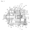
- FIG. 2 is a sectional view of a variable capacity swash plate type compressor according to the present invention
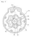
- FIG. 3 is a sectional view taken along the line of A-A of FIG. 2;
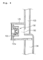
- FIG. 4 is a partially enlarged sectional view of a discharge muffler chamber of the variable capacity swash plate type compressor according to the present invention.
- FIG. 5 is a sectional view of a check valve of the variable capacity swash plate type compressor according to the present invention.
- FIG. 2 is a sectional view of a variable capacity swash plate type compressor according to the present invention
- FIG. 3 is a sectional view taken along the line of A-A of FIG. 2
- FIG. 4 is a partially enlarged sectional view of a discharge muffler chamber of the variable capacity swash plate type compressor
- FIG. 5 is a sectional view of a check valve of the variable capacity swash plate type compressor.
- variable capacity swash plate type compressor 100 includes: a cylinder block 110 having a plurality of cylinder bores 111 formed therein; a front housing 120 coupled to the front of the cylinder block 110 and having a sealed crank chamber 121 formed therein; a rear housing 130 coupled to the rear of the cylinder block 110 by interposing a valve unit 140 between the cylinder block 110 and the rear housing 130 and having a discharge chamber 132 and a suction chamber 131 formed by partitioning of a partitioning wall 134, the discharge chamber 132 being formed in the inner area and filled with refrigerant introduced from the cylinder block 110, the suction chamber 131 being formed in the outer area and filled with refrigerant introduced from the outside.
- the valve unit 140 includes: a valve plate 141 having a suction hole 142 and a discharge hole 143; a suction valve (not shown) mounted on a side of the valve plate 141 to open and close the suction hole 142; and a discharge valve (not shown) mounted on the other side of the valve plate 141 to open and close the discharge hole 143. So, the refrigerant is inhaled from the suction chamber 131 to the cylinder bore 111 during a suction stroke of the pistons 165, and then, a compressed refrigerant is discharged from the cylinder bore 111 to the discharge chamber 132 during a compression stroke of the pistons 165.
- the rear housing 130 has a discharge passageway 133 for discharging the refrigerant of the discharge chamber 132 to the outside, and a control valve 170 is mounted on a control valve port 136 of the rear housing 130 to properly control the capacity of the refrigerant contained in the crank chamber 121.
- a capacity control passageway 171 is fluidically communicated from the control valve port 136 to the crank chamber 121 to introduce the refrigerant and oil of the discharge chamber 132 to the crank chamber 121 when the control valve 170 is opened.
- the cylinder block 110 has a suction muffler chamber 113 formed on the outside thereof and having a suction port 112 to introduce refrigerant from the outside thereto, and the suction muffler chamber 113 is fluidically communicated with the suction chamber 131 of the rear housing 130.
- a driving shaft 150 is mounted on the cylinder block 110 and the front housing 120 and rotatably supported by interposing a bearing 122 therebetween.
- a rotor 161 is combined to the driving shaft 150 inside the crank chamber 121 to transmit a rotational force of the driving shaft 150 to a swash plate 160, and rotatably supported on the inner surface of the front housing 120.
- the swash plate 160 is connected to the rotor 161 via a hinge means 162 and mounted on the driving shaft 150 in such a way as to change an inclination angle in correspondence to a pressure change of the crank chamber 121.
- a sleeve 163 is mounted on the inner surface of the swash plate 160 in such a way as to allow an inclination of the swash plate 160 and slidably combined to the driving shaft 150.
- a plurality of pistons 165 are mounted on a slide face of the outer circumference of the swash plate 160 by interposing a pair of hemispherical shoes 166, which are faced with each other, between the pistons 165 and the swash plate 160, so that the plural pistons 165 can inhale and compress the refrigerant while performing a straight reciprocating motion inside the cylinder bore 111 according to the rotating motion of the swash plate 160.
- a compression coil spring 164 is mounted between the rotor 161 and the sleeve 163 to return the swash plate 160 to its initial position.
- a discharge muffler chamber 180 is formed inside the discharge chamber 132 to reduce a pulsating pressure of the discharged refrigerant.
- the discharge muffler chamber 180 is constructed in such a way that a circular division wall 135 is formed at the center of the discharge chamber 132 to partition the discharge muffler chamber 180 from the inside of the discharge chamber 132 and a check valve 190, which will be described later, is combined to an opening of the division wall 135.
- a check valve 190 is mounted on a refrigerant discharge channel of the rear housing 130 to circulate the refrigerant inside the compressor 100 and prevent a backflow of the refrigerant introduced from the outside when an air conditioner is in an off-state.
- the discharge muffler chamber 180 is formed by the check valve 190.
- the check valve 190 is coupled to the inner side of the division wall 135 to cover a side of the discharge muffler chamber 180, and in this instance, located at an end portion of the division wall 135 to secure a space for the discharge muffler chamber 180.
- the check valve 190 is forcibly pressed and coupled to the inner side of the division wall 135, and in this instance, a retainer 195 is mounted on the inner surface of the division wall 135 to prevent a separation of the check valve 190 from the division wall 135. Meanwhile, a seating jaw 135a is formed on the inner surface of the division wall 135 for seating the check valve 190 on the inner surface of the division wall 135.
- the check valve 190 is combined to the division wall 135 formed at the center of the discharge chamber 132, the check valve 190 is also mounted at the center of the discharge chamber 132 so as to prevent an overlapping phenomenon of a pulsating pressure waveform when a high-pressure refrigerant is discharged.
- the discharge muffler chamber 180 is formed by the check valve 190, components for forming the discharge muffler chamber 90 (used in the prior art) can be omitted, so that the compressor 100 according to the present invention can reduce the number of components and the number of work processes and reduce the pulsating pressure (pulsating noise), and the check valve 190 can be mounted without any increase in size of the compressor 100 since the check valve 190 is mounted in the discharge muffler chamber 180 securing a mounting area.
- the check valve 190 may be one of well-known various check valves. As shown in FIG. 5, the check valve 190 includes: a cover portion 191 inserted and coupled to the inner side of the division wall 135 and having a refrigerant inflow hole 191a formed at the center thereof; a valve body 192 coupled to a side of the cover portion 191 and having a refrigerant outflow hole 192a formed therein; and a valve 193 fluidically mounted between the cover portion 191 and the valve body 192 for elastically opening and closing the refrigerant inflow hole 191a by an elastic member 194 supported on the valve body 192.
- the valve body 192 has a section formed in a " ⁇ " shape, and includes a support jaw 192b protrudingly formed at the inner center thereof for supporting the elastic member 194 and a flange 192c formed at the outer peripheral surface of a side thereof.
- the cover portion 191 and the valve body 192 are coupled with each other in such a way that the valve body 192 is inserted into a bead 191b protrudingly formed on a side of the cover portion 191 and the bead 191b is bent to surround the flange 192c of the valve body 192.
- the check valve 190 is not opened because the volume of the discharged refrigerant is very small and pressure is meager. That is, since the check valve 190 is opened only when pressure more than a predetermined level is applied, the check valve 190 is not opened because pressure is meager at the minimum inclination angle of the swash plate when the air conditioner is in the off-state.
- the compressor 100 does not discharge the refrigerant contained therein to the outside but circulates it therein and prevents the backflow of the refrigerant introduced from the outside.
- variable capacity swash plate type compressor 100 According to the present invention, a refrigerant circulation process of the variable capacity swash plate type compressor 100 according to the present invention will be described.
- the swash plate 160 mounted on the driving shaft 150 is shaken in back and forth directions while rotating together with the driving shaft 150, and thereby, the plural pistons 165 combined to the outer circumference of the swash plate 160 repeat the suction and compression strokes while performing the reciprocating motion inside the cylinder bore 111 of the cylinder block 110 in order.
- the suction valve (not shown) of the valve unit 140 is opened by a pressure drop of the cylinder bore 111 so that the cylinder bore 111 and the suction chamber 131 are fluidically communicated with each other, the refrigerant supplied from the outside to the suction chamber 131 through the suction port 112 and the suction muffler chamber 113 is introduced into the cylinder bore 111.
- the refrigerant discharged to the discharge chamber 132 is a high-temperature and high-pressure refrigerant, and so the check valve 190 is opened by the high-pressure refrigerant.
- the check valve 190 is opened, the refrigerant discharged to the discharge chamber 132 moves to the discharge muffler chamber 180 after passing through the refrigerant inflow hole 191a and the refrigerant outflow hole 192a, and then, is discharged to the outside through the discharge passageway 133.
- the refrigerant is expanded in the discharge chamber 132, reduced while passing through the check valve 190, and expanded again in the discharge muffler chamber 180, so that the pulsating pressure of the discharged refrigerant is reduced.
- the check valve 190 is closed, so that the refrigerant circulates inside the compressor 100.
- variable capacity swash plate type compressor can reduce the number of components and the number of work processes and reduce the pulsating pressure (pulsating noise) of discharged refrigerant since the check valve, which circulates the refrigerant inside the compressor and prevents the backflow of the refrigerant when the air conditioner is in the off-state, is mounted on a side of the discharge muffler chamber in a cover type and the discharge muffler chamber is formed by the check valve.
- variable capacity swash plate type compressor can allow that the check valve is mounted in the discharge muffler chamber, which secures the mounting space for the check valve, without any increase in size of the compressor.
- variable capacity swash plate type compressor can prevent the overlapping phenomenon of the pulsating pressure waveform when the high-pressure refrigerant is discharged since the check valve is located at the center of a discharge chamber.
- variable capacity swash plate type compressor can prevent the separation of the check valve by fixing the check valve in the discharge chamber via the retainer.
Landscapes
- Engineering & Computer Science (AREA)
- Mechanical Engineering (AREA)
- General Engineering & Computer Science (AREA)
- Compressors, Vaccum Pumps And Other Relevant Systems (AREA)
- Compressor (AREA)
Applications Claiming Priority (1)
| Application Number | Priority Date | Filing Date | Title |
|---|---|---|---|
| KR1020060039203A KR101165947B1 (ko) | 2006-05-01 | 2006-05-01 | 가변용량형 사판식 압축기 |
Publications (2)
| Publication Number | Publication Date |
|---|---|
| EP1852607A1 true EP1852607A1 (de) | 2007-11-07 |
| EP1852607B1 EP1852607B1 (de) | 2013-11-20 |
Family
ID=38068887
Family Applications (1)
| Application Number | Title | Priority Date | Filing Date |
|---|---|---|---|
| EP07008652.5A Active EP1852607B1 (de) | 2006-05-01 | 2007-04-27 | Taumelscheibenkompressor mit veränderlicher Förderleistung |
Country Status (5)
| Country | Link |
|---|---|
| US (1) | US20070253837A1 (de) |
| EP (1) | EP1852607B1 (de) |
| JP (1) | JP4606433B2 (de) |
| KR (1) | KR101165947B1 (de) |
| CN (1) | CN101067410A (de) |
Cited By (3)
| Publication number | Priority date | Publication date | Assignee | Title |
|---|---|---|---|---|
| WO2009079727A1 (en) * | 2007-12-26 | 2009-07-02 | Whirlpool S.A. | System for attenuating pulsation in the gas discharge of a refrigeration compressor |
| EP3018347A1 (de) * | 2014-11-05 | 2016-05-11 | Delphi Technologies, Inc. | Verdichter mit variabler verdrängung mit ölrückschlagventil |
| JP2019520520A (ja) * | 2016-11-30 | 2019-07-18 | ハンオン システムズ | 電動圧縮機 |
Families Citing this family (7)
| Publication number | Priority date | Publication date | Assignee | Title |
|---|---|---|---|---|
| KR101001564B1 (ko) * | 2008-11-20 | 2010-12-17 | 주식회사 두원전자 | 로터리밸브를 장착한 사판식 압축기 |
| JP6164135B2 (ja) | 2014-03-27 | 2017-07-19 | 株式会社豊田自動織機 | 圧縮機 |
| CN104179656B (zh) * | 2014-08-18 | 2016-09-21 | 合肥达因汽车空调有限公司 | 一种变排量旋转斜盘式压缩机 |
| JP6469994B2 (ja) * | 2014-09-01 | 2019-02-13 | サンデンホールディングス株式会社 | 圧縮機 |
| KR102103440B1 (ko) | 2015-09-22 | 2020-04-23 | 한온시스템 주식회사 | 가변 용량형 사판식 압축기 |
| KR102076967B1 (ko) * | 2017-04-11 | 2020-02-13 | 한온시스템 주식회사 | 흡입 맥동 저감 장치 및 이를 포함한 사판식 압축기 |
| KR102717005B1 (ko) * | 2020-02-19 | 2024-10-15 | 한온시스템 주식회사 | 체크밸브 및 이를 포함하는 사판식 압축기 |
Citations (5)
| Publication number | Priority date | Publication date | Assignee | Title |
|---|---|---|---|---|
| EP0940581A2 (de) * | 1998-03-06 | 1999-09-08 | Kabushiki Kaisha Toyoda Jidoshokki Seisakusho | Druckpulsationsdämpfer für das Auslassventil eines Kompressors |
| EP1174619A2 (de) * | 2000-07-17 | 2002-01-23 | Kabushiki Kaisha Toyota Jidoshokki | Gehäuse eines Taumelscheibenkompressors |
| EP1293670A2 (de) * | 2001-09-13 | 2003-03-19 | Delphi Technologies, Inc. | Zylinderkopf eines Taumelscheibenkompressors mit Ölbarriere |
| EP1394410A2 (de) * | 2002-08-29 | 2004-03-03 | Halla Climate Control Corporation | Kompressor mit reduzierter Druck Pulsierung |
| EP1477670A2 (de) * | 2003-05-08 | 2004-11-17 | Kabushiki Kaisha Toyota Jidoshokki | Vorrichtung zum Ölabscheiden für einen Kühlmittelkompressor |
Family Cites Families (7)
| Publication number | Priority date | Publication date | Assignee | Title |
|---|---|---|---|---|
| JPH08109880A (ja) * | 1994-10-11 | 1996-04-30 | Toyota Autom Loom Works Ltd | 可変容量型圧縮機の動作制御システム |
| US6203284B1 (en) * | 1995-10-26 | 2001-03-20 | Kabushiki Kaisha Toyoda Jidoshokki Seisakusho | Valve arrangement at the discharge chamber of a variable displacement compressor |
| JP2000055223A (ja) | 1998-08-07 | 2000-02-22 | Toyota Autom Loom Works Ltd | 差圧制御弁及び圧縮機 |
| JP2000345967A (ja) | 1999-06-07 | 2000-12-12 | Toyota Autom Loom Works Ltd | 容量可変型圧縮機 |
| JP4066563B2 (ja) * | 1999-06-07 | 2008-03-26 | 株式会社豊田自動織機 | 逆止弁 |
| JP3864673B2 (ja) * | 2000-06-27 | 2007-01-10 | 株式会社豊田自動織機 | 圧縮機 |
| JP3778836B2 (ja) * | 2001-10-09 | 2006-05-24 | サンデン株式会社 | 逆止弁 |
-
2006
- 2006-05-01 KR KR1020060039203A patent/KR101165947B1/ko not_active Expired - Lifetime
-
2007
- 2007-04-26 US US11/796,464 patent/US20070253837A1/en not_active Abandoned
- 2007-04-27 EP EP07008652.5A patent/EP1852607B1/de active Active
- 2007-04-29 CN CNA2007101077763A patent/CN101067410A/zh active Pending
- 2007-05-01 JP JP2007121050A patent/JP4606433B2/ja active Active
Patent Citations (5)
| Publication number | Priority date | Publication date | Assignee | Title |
|---|---|---|---|---|
| EP0940581A2 (de) * | 1998-03-06 | 1999-09-08 | Kabushiki Kaisha Toyoda Jidoshokki Seisakusho | Druckpulsationsdämpfer für das Auslassventil eines Kompressors |
| EP1174619A2 (de) * | 2000-07-17 | 2002-01-23 | Kabushiki Kaisha Toyota Jidoshokki | Gehäuse eines Taumelscheibenkompressors |
| EP1293670A2 (de) * | 2001-09-13 | 2003-03-19 | Delphi Technologies, Inc. | Zylinderkopf eines Taumelscheibenkompressors mit Ölbarriere |
| EP1394410A2 (de) * | 2002-08-29 | 2004-03-03 | Halla Climate Control Corporation | Kompressor mit reduzierter Druck Pulsierung |
| EP1477670A2 (de) * | 2003-05-08 | 2004-11-17 | Kabushiki Kaisha Toyota Jidoshokki | Vorrichtung zum Ölabscheiden für einen Kühlmittelkompressor |
Cited By (5)
| Publication number | Priority date | Publication date | Assignee | Title |
|---|---|---|---|---|
| WO2009079727A1 (en) * | 2007-12-26 | 2009-07-02 | Whirlpool S.A. | System for attenuating pulsation in the gas discharge of a refrigeration compressor |
| CN101932835A (zh) * | 2007-12-26 | 2010-12-29 | 惠而浦股份有限公司 | 用于在制冷压缩机的气体排放中衰减脉动的系统 |
| EP3018347A1 (de) * | 2014-11-05 | 2016-05-11 | Delphi Technologies, Inc. | Verdichter mit variabler verdrängung mit ölrückschlagventil |
| US10066618B2 (en) | 2014-11-05 | 2018-09-04 | Mahle International Gmbh | Variable displacement compressor with an oil check valve |
| JP2019520520A (ja) * | 2016-11-30 | 2019-07-18 | ハンオン システムズ | 電動圧縮機 |
Also Published As
| Publication number | Publication date |
|---|---|
| JP2007298039A (ja) | 2007-11-15 |
| CN101067410A (zh) | 2007-11-07 |
| EP1852607B1 (de) | 2013-11-20 |
| KR20070106857A (ko) | 2007-11-06 |
| KR101165947B1 (ko) | 2012-07-18 |
| US20070253837A1 (en) | 2007-11-01 |
| JP4606433B2 (ja) | 2011-01-05 |
Similar Documents
| Publication | Publication Date | Title |
|---|---|---|
| EP1852607B1 (de) | Taumelscheibenkompressor mit veränderlicher Förderleistung | |
| US5647395A (en) | Valved discharge mechanism of a fluid displacement apparatus | |
| CN102124224B (zh) | 斜盘式压缩机的排出止回阀 | |
| US5632609A (en) | Valved discharge mechanism of a refrigerant compressor | |
| EP1953385A2 (de) | Taumelscheibenverdichter | |
| US5533871A (en) | Single-headed-piston-type swash-plate compressor having pulsation damping system | |
| EP1491769B1 (de) | Vorrichtung mit einem Druckpulsationsdämpfer und einen Durchgang bildendes Gehäuse | |
| US5213488A (en) | Valved discharge mechanism of a refrigerant compressor | |
| US5249939A (en) | Valved discharge mechanism of a refrigerant compressor | |
| AU608243B2 (en) | Slant plate type compressor with variable displacement mechanism | |
| EP1394410B1 (de) | Kompressor mit reduzierter Druck Pulsierung | |
| KR101205221B1 (ko) | 가변용량형 사판식 압축기 | |
| JP3433849B2 (ja) | 往復動型圧縮機 | |
| KR101205220B1 (ko) | 가변용량형 사판식 압축기 | |
| US9810209B2 (en) | Compressor | |
| KR102130406B1 (ko) | 압축기 | |
| KR102130407B1 (ko) | 압축기 | |
| KR101177294B1 (ko) | 가변용량형 사판식 압축기 | |
| US7150603B2 (en) | Compressor | |
| KR101866731B1 (ko) | 가변 용량형 사판식 압축기 | |
| EP1947336A1 (de) | Hubkolbenverdichter | |
| US20090148312A1 (en) | Variable Capacity Swash Plate Type Compressor | |
| EP1041284A2 (de) | Einlassventil für Kompressor | |
| KR20060047082A (ko) | 자동차 압축기의 밸브유니트 구조 | |
| JP2007146769A (ja) | 往復動型圧縮機 |
Legal Events
| Date | Code | Title | Description |
|---|---|---|---|
| PUAI | Public reference made under article 153(3) epc to a published international application that has entered the european phase |
Free format text: ORIGINAL CODE: 0009012 |
|
| AK | Designated contracting states |
Kind code of ref document: A1 Designated state(s): AT BE BG CH CY CZ DE DK EE ES FI FR GB GR HU IE IS IT LI LT LU LV MC MT NL PL PT RO SE SI SK TR |
|
| AX | Request for extension of the european patent |
Extension state: AL BA HR MK YU |
|
| 17P | Request for examination filed |
Effective date: 20071123 |
|
| 17Q | First examination report despatched |
Effective date: 20080220 |
|
| AKX | Designation fees paid |
Designated state(s): DE FR |
|
| GRAP | Despatch of communication of intention to grant a patent |
Free format text: ORIGINAL CODE: EPIDOSNIGR1 |
|
| INTG | Intention to grant announced |
Effective date: 20130612 |
|
| GRAS | Grant fee paid |
Free format text: ORIGINAL CODE: EPIDOSNIGR3 |
|
| RAP1 | Party data changed (applicant data changed or rights of an application transferred) |
Owner name: HALLA VISTEON CLIMATE CONTROL CORP. |
|
| GRAA | (expected) grant |
Free format text: ORIGINAL CODE: 0009210 |
|
| AK | Designated contracting states |
Kind code of ref document: B1 Designated state(s): DE FR |
|
| REG | Reference to a national code |
Ref country code: DE Ref legal event code: R096 Ref document number: 602007033842 Country of ref document: DE Effective date: 20140116 |
|
| REG | Reference to a national code |
Ref country code: DE Ref legal event code: R097 Ref document number: 602007033842 Country of ref document: DE |
|
| PLBE | No opposition filed within time limit |
Free format text: ORIGINAL CODE: 0009261 |
|
| STAA | Information on the status of an ep patent application or granted ep patent |
Free format text: STATUS: NO OPPOSITION FILED WITHIN TIME LIMIT |
|
| 26N | No opposition filed |
Effective date: 20140821 |
|
| REG | Reference to a national code |
Ref country code: DE Ref legal event code: R097 Ref document number: 602007033842 Country of ref document: DE Effective date: 20140821 |
|
| REG | Reference to a national code |
Ref country code: FR Ref legal event code: PLFP Year of fee payment: 10 |
|
| REG | Reference to a national code |
Ref country code: DE Ref legal event code: R082 Ref document number: 602007033842 Country of ref document: DE Representative=s name: SCHWABE SANDMAIR MARX PATENTANWAELTE RECHTSANW, DE Ref country code: DE Ref legal event code: R082 Ref document number: 602007033842 Country of ref document: DE Representative=s name: SSM SANDMAIR PATENTANWAELTE RECHTSANWALT PARTN, DE |
|
| REG | Reference to a national code |
Ref country code: FR Ref legal event code: PLFP Year of fee payment: 11 |
|
| REG | Reference to a national code |
Ref country code: FR Ref legal event code: PLFP Year of fee payment: 12 |
|
| P01 | Opt-out of the competence of the unified patent court (upc) registered |
Effective date: 20230615 |
|
| PGFP | Annual fee paid to national office [announced via postgrant information from national office to epo] |
Ref country code: DE Payment date: 20250305 Year of fee payment: 19 |
|
| PGFP | Annual fee paid to national office [announced via postgrant information from national office to epo] |
Ref country code: FR Payment date: 20260309 Year of fee payment: 20 |