EP1852641B1 - Sperrventil mit geteilter Klappe und Mechanismus zum Reduzieren der Drehfederabnutzung - Google Patents
Sperrventil mit geteilter Klappe und Mechanismus zum Reduzieren der Drehfederabnutzung Download PDFInfo
- Publication number
- EP1852641B1 EP1852641B1 EP20070107543 EP07107543A EP1852641B1 EP 1852641 B1 EP1852641 B1 EP 1852641B1 EP 20070107543 EP20070107543 EP 20070107543 EP 07107543 A EP07107543 A EP 07107543A EP 1852641 B1 EP1852641 B1 EP 1852641B1
- Authority
- EP
- European Patent Office
- Prior art keywords
- valve plate
- shaft
- lug
- torsion spring
- valve
- Prior art date
- Legal status (The legal status is an assumption and is not a legal conclusion. Google has not performed a legal analysis and makes no representation as to the accuracy of the status listed.)
- Not-in-force
Links
- 239000000463 material Substances 0.000 description 5
- 238000011144 upstream manufacturing Methods 0.000 description 4
- 229910000531 Co alloy Inorganic materials 0.000 description 1
- 230000004048 modification Effects 0.000 description 1
- 238000012986 modification Methods 0.000 description 1
- 230000002093 peripheral effect Effects 0.000 description 1
- 230000001105 regulatory effect Effects 0.000 description 1
- 239000010935 stainless steel Substances 0.000 description 1
- 229910001220 stainless steel Inorganic materials 0.000 description 1
Images


Classifications
-
- F—MECHANICAL ENGINEERING; LIGHTING; HEATING; WEAPONS; BLASTING
- F16—ENGINEERING ELEMENTS AND UNITS; GENERAL MEASURES FOR PRODUCING AND MAINTAINING EFFECTIVE FUNCTIONING OF MACHINES OR INSTALLATIONS; THERMAL INSULATION IN GENERAL
- F16K—VALVES; TAPS; COCKS; ACTUATING-FLOATS; DEVICES FOR VENTING OR AERATING
- F16K15/00—Check valves
- F16K15/02—Check valves with guided rigid valve members
- F16K15/03—Check valves with guided rigid valve members with a hinged closure member or with a pivoted closure member
- F16K15/033—Check valves with guided rigid valve members with a hinged closure member or with a pivoted closure member spring-loaded
-
- F—MECHANICAL ENGINEERING; LIGHTING; HEATING; WEAPONS; BLASTING
- F16—ENGINEERING ELEMENTS AND UNITS; GENERAL MEASURES FOR PRODUCING AND MAINTAINING EFFECTIVE FUNCTIONING OF MACHINES OR INSTALLATIONS; THERMAL INSULATION IN GENERAL
- F16K—VALVES; TAPS; COCKS; ACTUATING-FLOATS; DEVICES FOR VENTING OR AERATING
- F16K15/00—Check valves
- F16K15/02—Check valves with guided rigid valve members
- F16K15/03—Check valves with guided rigid valve members with a hinged closure member or with a pivoted closure member
- F16K15/035—Check valves with guided rigid valve members with a hinged closure member or with a pivoted closure member with a plurality of valve members
- F16K15/036—Dual valve members with hinges crossing the flow line substantially diametrical
- F16K15/038—Dual valve members with hinges crossing the flow line substantially diametrical having a common hinge
-
- Y—GENERAL TAGGING OF NEW TECHNOLOGICAL DEVELOPMENTS; GENERAL TAGGING OF CROSS-SECTIONAL TECHNOLOGIES SPANNING OVER SEVERAL SECTIONS OF THE IPC; TECHNICAL SUBJECTS COVERED BY FORMER USPC CROSS-REFERENCE ART COLLECTIONS [XRACs] AND DIGESTS
- Y10—TECHNICAL SUBJECTS COVERED BY FORMER USPC
- Y10T—TECHNICAL SUBJECTS COVERED BY FORMER US CLASSIFICATION
- Y10T137/00—Fluid handling
- Y10T137/7722—Line condition change responsive valves
- Y10T137/7837—Direct response valves [i.e., check valve type]
- Y10T137/7838—Plural
- Y10T137/7839—Dividing and recombining in a single flow path
Definitions
- the present invention relates to split flapper check valves and, more particularly, to a split flapper check valve that has reduced wear of a torsion spring implemented therein.
- split flapper check valves may be used in any one of numerous circumstances in which air flow may need to be regulated.
- the valve is implemented in an air distribution system.
- the air distribution system includes an inlet duct that receives air from an air source and two or more outlet ducts that exhaust the received air to a desired area within the aircraft, such as, for example, to an aircraft cabin or an underfloor section of the aircraft.
- the valve is disposed between the inlet and outlet ducts to prevent reverse flow in the air distribution system by moving between open and closed positions.
- the valve includes a valve body having an opening formed therethrough, a shaft that extends across the opening, two valve plates rotationally mounted on the shaft via lugs, and a torsion spring also mounted on the shaft between the lugs. The ends of the torsion spring are coupled to the two valve plates.
- the torsion spring maintains the valve plates seated against the valve body.
- one or both of the valve plates unseat from the valve body to allow air to flow through the valve body opening.
- split flapper check valves such as the one described above, generally operate safely and reliably, these valves can exhibit certain drawbacks.
- the torsion spring may have a length that is less than the distance between the lugs.
- the torsion spring position may shift during operation and may undesirably abrade against the shaft, lugs, or the valve plates.
- wear of the spring against the hinge pin may occur when the flappers rotate to the open and closed positions. Consequently, the spring and/or the valve plates may prematurely wear and may need to be repeatedly replaced.
- the present invention provides a split flapper check valve that includes a torsion spring wear reduction mechanism to at least inhibit the torsion spring from abrading against the shaft or valve plate.
- a split flapper check valve includes a valve body, a shaft, a first valve plate, a second valve plate, a torsion spring, a first bushing, and a second bushing.
- the valve body includes one or more flow passages formed therethrough.
- the shaft is coupled to the valve body.
- the first valve plate is rotationally mounted on the shaft, and includes a first lug extending therefrom that has a shaft opening formed therethrough through which the shaft extends.
- the second valve plate is rotationally mounted on the shaft, and includes a first lug extending therefrom that has a shaft opening formed therethrough through which the shaft extends.
- the second valve plate first lug is spaced apart from the first valve plate first lug.
- the torsion spring is mounted on, and surrounds at least a portion of, the shaft between the first and second valve plate first lugs, and has at least a first end and a second end.
- the first bushing is mounted on the shaft and has an axial section and a radial section.
- the axial section is disposed between the torsion spring and the shaft, and the radial section extends radially outwardly from the axial section and is disposed between the torsion spring first end and the first valve plate first lug.
- the second bushing is mounted on the shaft and has an axial section and a radial section.
- the axial section is disposed between the torsion spring and the shaft, and the radial section extends radially outwardly from the axial section and is disposed between the torsion spring second end and the second valve plate first lug.
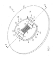
- FIG. 1 is a perspective view of an exemplary split flapper check valve
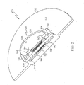
- FIG. 2 is a cross section view of the split flapper check valve depicted in FIG. 1 taken along line 2-2;
- FIG. 3 is a close up of a portion of the split flapper check valve shown in FIG. 2 ;
- FIG. 4 is a cross section view of another exemplary split flapper check valve.
- the check valve 100 includes a valve body 102, a shaft 104, one or more valve plates 108, 110, one or more torsion springs 112, and one or more bushings 114 (not visible in FIG. 1 ).
- the valve body 102 is configured to be coupled between two non-illustrated duct segments and includes a seat 116 with which the one or more valve plates 108, 110 contact when in a closed position.
- the valve body 102 includes an annular shroud 118 and a pair of mounting flanges 120, 122.
- the annular shroud 118 has one or more flow passages (124) formed therein through which air flows when the one or more valve plates 108, 110 are in an open position.
- the mounting flanges 120, 122 extend from the annular shroud 118 in a downstream direction, and each includes a shaft opening within which each end of the shaft 104 is disposed.
- valve plates 108, 110 are configured to move between an open position to unseal the one or more flow passages 124, and a closed position to substantially seal the one or more flow passages 124. It is noted that in FIGS. 1 and 2 , valve plate 108 is depicted in the open position, and in FIG. 1 , valve plate 110 is depicted in the closed position.
- Each valve plate 108, 110 is rotationally mounted on the shaft 120, 122 and has an upstream face 126, 128 and a downstream face 130, 132.
- Each upstream face 126, 128 includes an outer periphery 134, 136 that contacts the valve seat 116 when in the closed position.
- Each downstream face 130, 132 includes a pair of lugs, specifically, a first pair of lugs 138, 140, and a second pair of lugs 142, 144.
- the lugs 138, 140, 142, 144 extend from their corresponding downstream faces 130, 132 in the downstream direction.
- Each lug 138, 140, 142, 144 has an opening formed therein through which the shaft 104 extends.
- both lugs of the first pair of lugs 138, 140 may be disposed between the lugs of the second pair of lugs 142, 144, or vice versa.
- the valve plates 108, 110 are preferably biased toward the closed position via a torsion spring 112.
- the torsion spring 112 surrounds at least a portion of the shaft 114, between the lugs 138, 140, 142, 144.
- the torsion spring 112 is coupled to one lug 138 of the first pair of lugs 138, 140, to one lug 142 of the second pair of lugs 142, 144, and contacts each of the valve plates 108, 110 to supply a torsion force that biases the valve plates 108, 110 toward the closed position.
- valve plates 108, 110 moves, against the bias of the torsion spring 112, to the open position.
- the torsion spring 112 may be coupled to the valve plates 108, 110, to thereby supply the torsion force thereto, in any one of numerous ways, not just by contacting each valve plate 108, 110, as in the depicted embodiment.
- the bushings 114 are included.
- the bushings 114 are mounted on the shaft 104 and are preferably made of material that does not abrade against the shaft 104, the torsion spring 112, the lugs 138, 140, 142, 144 or any other components of the check valve 100 with which it contacts.
- the particular material selected depends on the materials from which the shaft 104, the torsion spring 112, the lugs 138, 140, 142, 144, and other components are constructed.
- the shaft 104, the torsion spring 112, and the lugs 138, 140, 142, 144 are made from stainless steel; in such case, the bushings 114 may be constructed from cobalt alloys, or any other suitable material.
- each bushing 114 includes an axial section 146 and a radial section 148.
- the axial section 146 is configured to have a diameter that is smaller than an inner diameter of the torsion spring 112 so that it may be inserted therein; consequently, when the check valve 100 is fully assembled, the axial section 146 is disposed between the shaft 104 and the spring 112.
- the radial section 148 extends radially outwardly from a portion of the axial section 146 and has an outer peripheral diameter that is greater than an outer diameter of the torsion spring 112.
- the radial section 148 at least in the depicted embodiment, seats agains a portion of the of the lugs 138, 140, 142, 144.
- the bushings 114 are disposed one each at either end of the torsion spring 112 so that the radial section 148 of each of the bushings 114 is disposed between the torsion spring 112 and an adjacent lug 138, 140. It will be appreciated that in some cases, the torsion spring 112 may be short relative to the distance between the lugs lugs 138, 140. In such case, the bushing 114 radial sections 148 may be relatively thick. In other embodiments, the torsion spring 112 may be long relative to the distance between the lugs 138, 140, or the torsion spring 112 may have relatively small inner and outer diameters and may need additional support along its length. In such case, as shown in FIG.
- a tubular sleeve 150 having an outer diameter that is smaller than the torsion spring 112 inner diameter may be positioned between the bushings 114.
- the bushings 114 are depicted in FIG. 3 as separate pieces from other components of the split flapper check valve 100, it will be appreciated that in some embodiments, such as the embodiment depicted in FIG. 4 , one or more of the bushings 114 may be formed as an integral part of the lugs 138, 140.
- a split flapper check valve 100 has now been provided that includes a torsion spring that does not abrade against the shaft or valve plate.
- the valve to be relatively inexpensive to implement.
Landscapes
- Engineering & Computer Science (AREA)
- General Engineering & Computer Science (AREA)
- Mechanical Engineering (AREA)
- Check Valves (AREA)
Claims (10)
- Sperrventil (100) mit geteilter Klappe mit
einem Ventilkörper (102), der einen oder mehrere durch ihn hindurch ausgebildete Strömungsdurchgänge (124) aufweist,
einer an den Ventilkörper (102) gekoppelten Welle (104),
einer ersten Ventilscheibe (108), die drehungsmäßig an der Welle (104) montiert ist und eine erste sich davon erstreckende Nase (138) aufweist, durch die eine Wellenöffnung ausgebildet ist, durch die sich die Welle (104) erstreckt,
einer zweiten Ventilscheibe (110), die drehungsmäßig an der Welle (104) montiert ist und eine erste sich davon erstreckende Nase (142) aufweist, durch die eine Wellenöffnung ausgebildet ist, durch die sich die Welle (104) erstreckt, wobei die erste Nase (142) der zweiten Ventilscheibe von der ersten Nase (138) der ersten Ventilscheibe beabstandet ist,
einer Drehfeder (112), die an der Welle (104) zwischen den ersten Nasen (138, 142) der ersten und der zweiten Ventilscheibe (108) montiert ist und mindestens einen Abschnitt davon umgibt, wobei die Drehfeder (112) mindestens ein erstes Ende und ein zweites Ende hat,
einer ersten Buchse (114), die an der Welle (104) montiert ist und einen axialen Abschnitt (146) und einen radialen Abschnitt (148) hat, wobei der axiale Abschnitt (146) zwischen der Drehfeder (112) und der Welle (104) angeordnet ist und sich der radiale Abschnitt (148) vom axialen Abschnitt (146) radial nach außen erstreckt und zwischen dem ersten Ende der Drehfeder und der ersten Nase (138) der ersten Ventilscheibe angeordnet ist, und einer zweiten Buchse (114), die an der Welle (104) montiert ist und einen axialen Abschnitt (146) und einen radialen Abschnitt (148) hat, wobei der axiale Abschnitt (146) zwischen der Drehfeder (112) und der Welle (104) angeordnet ist und sich der radiale Abschnitt (148) vom axialen Abschnitt (146) radial nach außen erstreckt und zwischen dem zweiten Ende der Drehfeder und der ersten Nase (142) der zweiten Ventilscheibe angeordnet ist. - Sperrventil mit geteilter Klappe nach Anspruch 1, ferner mit einer Hülse, die an der Welle (104) montiert ist, mindestens einen Abschnitt davon umgibt und zwischen der ersten und der zweiten Buchse (114) angeordnet ist.
- Sperrventil mit geteilter Klappe nach Anspruch 2, wobei der Außendurchmesser der Hülse kleiner als der Innendurchmesser der Drehfeder (112) ist.
- Sperrventil mit geteilter Klappe nach Anspruch 1, wobei die Drehfeder (112) einen Außendurchmesser hat, der radiale Abschnitt (148) der ersten Buchse jeweils einen Durchmesser hat und der Außendurchmesser der Drehfeder kleiner als der Durchmesser des radialen Abschnitts (148) der ersten Buchse ist.
- Sperrventil mit geteilter Klappe nach Anspruch 1, wobei die erste Buchse (114) an die erste Nase (138) der ersten Ventilscheibe gekoppelt ist.
- Sperrventil mit geteilter Klappe nach Anspruch 5, wobei die zweite Buchse (114) an die erste Nase (138) der zweiten Ventilscheibe gekoppelt ist.
- Sperrventil mit geteilter Klappe nach Anspruch 1, wobei ein erster Abschnitt der Drehfeder (112) an die erste Nase (138) der ersten Ventilscheibe gekoppelt ist und ein zweiter Abschnitt der Drehfeder (112) an die erste Nase (138) der zweiten Ventilscheibe gekoppelt ist.
- Sperrventil mit geteilter Klappe nach Anspruch 1, wobei
die erste Ventilscheibe (108) eine von der ersten Nase (138) der ersten Ventilscheibe beabstandete zweite Nase (138) aufweist,
die erste Nase (138) der zweiten Ventilscheibe zwischen der ersten und der zweiten Nase (138) der ersten Ventilscheibe angeordnet ist und
die Drehfeder (112) zwischen der ersten Nase (138) der ersten Ventilscheibe und der ersten Nase (138) der zweiten Ventilscheibe angeordnet ist. - Sperrventil mit geteilter Klappe nach Anspruch 8, wobei die zweite Ventilscheibe (108) eine zweite Nase (142) aufweist, die außerhalb der ersten und der zweite Nase (138) der ersten Ventilscheibe (108) angeordnet ist.
- Sperrventil (100) mit geteilter Klappe mit
einem Ventilkörper (102), der einen oder mehrere durch ihn hindurch ausgebildete Strömungsdurchgänge (124) aufweist,
einer an den Ventilkörper (102) gekoppelten Welle (104),
einer ersten Ventilscheibe (108), die drehungsmäßig an der Welle (104) montiert ist und eine erste und eine zweite sich davon erstreckende Nase (138, 140) aufweist, wobei durch jede Nase eine Wellenöffnung ausgebildet ist, durch die sich die Welle (104) erstreckt,
einer zweiten Ventilscheibe (110), die drehungsmäßig an der Welle (104) montiert ist und eine erste und eine zweite sich davon erstreckende Nase (142, 144) aufweist, wobei durch jede Nase eine Wellenöffnung ausgebildet ist, durch die sich die Welle (104) erstreckt, wobei die erste Nase (142) der zweiten Ventilscheibe zwischen der ersten und der zweiten Nase (138, 140) der ersten Ventilscheibe angeordnet ist und einen sich axial erstreckenden Abschnitt und einen sich radial erstreckenden Abschnitt, die daran ausgebildet sind, aufweist,
einer Drehfeder (112) mit einem ersten Abschnitt, der die Welle (104) zwischen den Nasen der ersten und der zweiten Ventilscheibe umgibt, und einem zweiten Abschnitt, der an dem sich axial erstreckenden Abschnitt der ersten Nase (142) der zweiten Ventilscheibe montiert ist, wobei die Drehfeder (112) ein erstes und ein zweites Ende hat, und
einem Buchsenabschnitt (114), der sich von der ersten Nase (138) der ersten Ventilscheibe erstreckt und an der Welle (104) montiert ist, wobei der Buchsenabschnitt (114) einen axialen Abschnitt (146) und einen radialen Abschnitt (148) hat, wobei sich der axiale Abschnitt (146) axial von der ersten Nase (138) der ersten Ventilscheibe erstreckt und zwischen der Drehfeder (112) und der Welle (104) angeordnet ist und sich der radiale Abschnitt (148) vom axialen Abschnitt (146) radial nach außen erstreckt und zwischen der Drehfeder (112) und der ersten Nase (138) der ersten Ventilscheibe angeordnet ist.
Applications Claiming Priority (1)
| Application Number | Priority Date | Filing Date | Title |
|---|---|---|---|
| US11/418,799 US20070256740A1 (en) | 2006-05-05 | 2006-05-05 | Split flapper check valve including a torsion spring wear reduction mechanism |
Publications (2)
| Publication Number | Publication Date |
|---|---|
| EP1852641A1 EP1852641A1 (de) | 2007-11-07 |
| EP1852641B1 true EP1852641B1 (de) | 2008-12-10 |
Family
ID=38294039
Family Applications (1)
| Application Number | Title | Priority Date | Filing Date |
|---|---|---|---|
| EP20070107543 Not-in-force EP1852641B1 (de) | 2006-05-05 | 2007-05-04 | Sperrventil mit geteilter Klappe und Mechanismus zum Reduzieren der Drehfederabnutzung |
Country Status (3)
| Country | Link |
|---|---|
| US (1) | US20070256740A1 (de) |
| EP (1) | EP1852641B1 (de) |
| DE (1) | DE602007000338D1 (de) |
Cited By (1)
| Publication number | Priority date | Publication date | Assignee | Title |
|---|---|---|---|---|
| US9611947B2 (en) | 2015-06-09 | 2017-04-04 | Ge Aviation Systems Llc | Valve assembly and method of controlling flow of fluid |
Families Citing this family (12)
| Publication number | Priority date | Publication date | Assignee | Title |
|---|---|---|---|---|
| US20120180880A1 (en) * | 2011-01-19 | 2012-07-19 | Cameron International Corporation | Dual plate wafer check valve |
| CN102829219B (zh) * | 2012-09-10 | 2014-06-11 | 浙江埃尼斯阀门有限公司 | 一种止回阀 |
| US9581256B2 (en) * | 2014-07-08 | 2017-02-28 | Hamilton Sundstrand Corporation | Valve flapper spring stop mechanism |
| US20160018012A1 (en) * | 2014-07-15 | 2016-01-21 | Hamilton Sundstrand Corporation | Check valve hinge pin |
| CN104265956B (zh) * | 2014-10-18 | 2016-03-30 | 魏伯卿 | 轴弹簧微阻力止回阀 |
| ES2677256B1 (es) * | 2017-01-31 | 2019-05-27 | Sener Ing & Sist | Válvula unidireccional para un dispositivo de captación de energía de las olas |
| US11156303B2 (en) | 2019-05-31 | 2021-10-26 | Mueller International, Llc | Break check valve for hydrant |
| US11098821B1 (en) | 2019-10-10 | 2021-08-24 | Cantex International, Inc. | Flapper valve |
| US11204102B2 (en) * | 2020-03-19 | 2021-12-21 | Mueller International, Llc | Watertight check valve |
| CN113819275A (zh) * | 2020-06-19 | 2021-12-21 | 杭州小米环境科技有限公司 | 排气阀 |
| US11725746B2 (en) | 2021-06-07 | 2023-08-15 | Mueller International, Llc | Low water hammer break check valve |
| US12422051B2 (en) | 2023-12-11 | 2025-09-23 | Us Valve Corporation | Internally installed check valve |
Family Cites Families (23)
| Publication number | Priority date | Publication date | Assignee | Title |
|---|---|---|---|---|
| US2221269A (en) * | 1937-02-25 | 1940-11-12 | Sertillange Maurice Antoine | Quick acting obturating flap valve |
| US3268202A (en) * | 1963-05-27 | 1966-08-23 | Dover Corp | Valve construction or the like |
| US3395727A (en) * | 1965-03-01 | 1968-08-06 | Anderson Greenwood & Co | Check valve |
| US3538946A (en) * | 1967-10-09 | 1970-11-10 | George W Hilsheimer | Check valve |
| US3678958A (en) * | 1970-09-16 | 1972-07-25 | Fmc Corp | Check valve |
| SE383401B (sv) * | 1973-06-08 | 1976-03-08 | Saab Scania Ab | Anordning vid backventiler av det slag som har ett ventilhus med rakt genomlopp och med ett cirkulert ventilsete anordnat lengs ett genomloppets symmetrilinje korsande plan, och ett spjell, som er vridbart m.m |
| US3930380A (en) * | 1974-08-19 | 1976-01-06 | General Motors Corporation | Ice dispenser container coupling |
| GB2120361B (en) * | 1978-08-18 | 1984-06-13 | Pegler Hattersley Australia Pt | Check valve |
| US4427025A (en) * | 1979-05-31 | 1984-01-24 | Prince Valve, Inc. | Swing check valve |
| NZ203837A (en) * | 1983-04-08 | 1986-09-10 | Moygro Mfg Ltd | Alarm check valve for sandwiching between flanges of pipes in automatic sprinkler system |
| JPS59194637U (ja) * | 1983-06-09 | 1984-12-24 | 株式会社 大金製作所 | ダンパ−デイスク |
| US4556083A (en) * | 1984-01-12 | 1985-12-03 | Vapor Corporation | Pressure relief valve and method for modification thereof |
| DE3402203A1 (de) * | 1984-01-24 | 1985-08-01 | Mark Controls Corp., 5568 Daun | Rueckschlagklappe |
| US4809960A (en) * | 1987-03-26 | 1989-03-07 | Nissan Motor Co., Ltd. | Bushing assembly |
| US4828235A (en) * | 1987-07-29 | 1989-05-09 | Michigan Spring Company | Torsion spring assembly |
| US4825902A (en) * | 1988-01-11 | 1989-05-02 | Halliburton Company | Flapper valve with protective hinge pin sleeve |
| US5301709A (en) * | 1993-04-01 | 1994-04-12 | Gulf Valve Company | Check valve and method of assembly |
| US5408899A (en) * | 1993-06-14 | 1995-04-25 | Brecom Subsidiary Corporation No. 1 | Foot pedal devices for controlling engines |
| US5368283A (en) * | 1993-08-05 | 1994-11-29 | Precision Products Group, Inc. | Torsion spring assembly with interlocking bushings |
| US5464197A (en) * | 1994-08-15 | 1995-11-07 | Ecclesfield; George | Torsion spring having an adjustable spring rate |
| US5479678A (en) * | 1995-02-21 | 1996-01-02 | Martin Marietta Corp. | Locking hinge |
| US6565445B1 (en) * | 2001-06-11 | 2003-05-20 | Auburn Clutch Co., Inc. | Torsional vibration dampening assembly |
| US7493770B2 (en) * | 2004-08-09 | 2009-02-24 | General Electric Company | Methods and apparatus for regulating airflow supply systems |
-
2006
- 2006-05-05 US US11/418,799 patent/US20070256740A1/en not_active Abandoned
-
2007
- 2007-05-04 DE DE200760000338 patent/DE602007000338D1/de not_active Expired - Fee Related
- 2007-05-04 EP EP20070107543 patent/EP1852641B1/de not_active Not-in-force
Cited By (1)
| Publication number | Priority date | Publication date | Assignee | Title |
|---|---|---|---|---|
| US9611947B2 (en) | 2015-06-09 | 2017-04-04 | Ge Aviation Systems Llc | Valve assembly and method of controlling flow of fluid |
Also Published As
| Publication number | Publication date |
|---|---|
| US20070256740A1 (en) | 2007-11-08 |
| DE602007000338D1 (de) | 2009-01-22 |
| EP1852641A1 (de) | 2007-11-07 |
Similar Documents
| Publication | Publication Date | Title |
|---|---|---|
| EP1852641A1 (de) | Sperrventil mit geteilter Klappe und Mechanismus zum Reduzieren der Drehfederabnutzung | |
| EP2034224A2 (de) | Rückschlagventile mit Rauschreduzierer | |
| EP1691117B1 (de) | Aufgeteiltes Schnappklappenventil | |
| EP2137438B1 (de) | Auslassventil mit mehrzweckfeder | |
| EP2818660B1 (de) | Ventilvorrichtung für einen abgasströmungspfad | |
| EP2430339B1 (de) | Ventilanordnung | |
| CN102667098B (zh) | 具有用于涡轮的环形旋转旁通阀的涡轮增压器 | |
| US7325569B2 (en) | Butterfly valve with integral split flapper relief valve | |
| EP2352939B1 (de) | Flüssigkeitsventil mit integrierter sicherheitsabsperrung | |
| US8047226B2 (en) | Pressure relief valves and pneumatic control systems | |
| US20080053536A1 (en) | High flow insert type check valve | |
| WO2011115816A1 (en) | Valves having ceramic trim with protected shut-off surfaces | |
| US8528880B2 (en) | Butterfly valve plate sealing assemblies | |
| US20120234408A1 (en) | Check valve with axial thrust element | |
| US20080078459A1 (en) | Rotary hydraulic damper for check valve | |
| US8276880B2 (en) | Butterfly valve plate sealing assembly | |
| JP2011179625A (ja) | ボールバルブ | |
| US8251086B2 (en) | Rotary gate valve with secondary seal | |
| US20100236650A1 (en) | Butterfly valve combined with check valve | |
| EP3537013B1 (de) | Lager für drehsteuerungsventil | |
| JP3075698B2 (ja) | デュアルプレート逆止弁 | |
| JP2969444B2 (ja) | デュアルプレート逆止弁 | |
| JP2969443B2 (ja) | デュアルプレート逆止弁 | |
| CN214836728U (zh) | 自适应阀组件及内燃机系统 | |
| US20090159827A1 (en) | Rotary gate valve |
Legal Events
| Date | Code | Title | Description |
|---|---|---|---|
| PUAI | Public reference made under article 153(3) epc to a published international application that has entered the european phase |
Free format text: ORIGINAL CODE: 0009012 |
|
| AK | Designated contracting states |
Kind code of ref document: A1 Designated state(s): AT BE BG CH CY CZ DE DK EE ES FI FR GB GR HU IE IS IT LI LT LU LV MC MT NL PL PT RO SE SI SK TR |
|
| AX | Request for extension of the european patent |
Extension state: AL BA HR MK YU |
|
| 17P | Request for examination filed |
Effective date: 20080213 |
|
| GRAP | Despatch of communication of intention to grant a patent |
Free format text: ORIGINAL CODE: EPIDOSNIGR1 |
|
| AKX | Designation fees paid |
Designated state(s): DE FR GB |
|
| GRAS | Grant fee paid |
Free format text: ORIGINAL CODE: EPIDOSNIGR3 |
|
| GRAA | (expected) grant |
Free format text: ORIGINAL CODE: 0009210 |
|
| AK | Designated contracting states |
Kind code of ref document: B1 Designated state(s): DE FR GB |
|
| REG | Reference to a national code |
Ref country code: GB Ref legal event code: FG4D |
|
| REF | Corresponds to: |
Ref document number: 602007000338 Country of ref document: DE Date of ref document: 20090122 Kind code of ref document: P |
|
| PGFP | Annual fee paid to national office [announced via postgrant information from national office to epo] |
Ref country code: FR Payment date: 20090507 Year of fee payment: 3 Ref country code: DE Payment date: 20090529 Year of fee payment: 3 |
|
| PLBE | No opposition filed within time limit |
Free format text: ORIGINAL CODE: 0009261 |
|
| STAA | Information on the status of an ep patent application or granted ep patent |
Free format text: STATUS: NO OPPOSITION FILED WITHIN TIME LIMIT |
|
| 26N | No opposition filed |
Effective date: 20090911 |
|
| REG | Reference to a national code |
Ref country code: FR Ref legal event code: ST Effective date: 20110131 |
|
| PG25 | Lapsed in a contracting state [announced via postgrant information from national office to epo] |
Ref country code: DE Free format text: LAPSE BECAUSE OF NON-PAYMENT OF DUE FEES Effective date: 20101201 |
|
| PG25 | Lapsed in a contracting state [announced via postgrant information from national office to epo] |
Ref country code: FR Free format text: LAPSE BECAUSE OF NON-PAYMENT OF DUE FEES Effective date: 20100531 |
|
| GBPC | Gb: european patent ceased through non-payment of renewal fee |
Effective date: 20110504 |
|
| PG25 | Lapsed in a contracting state [announced via postgrant information from national office to epo] |
Ref country code: GB Free format text: LAPSE BECAUSE OF NON-PAYMENT OF DUE FEES Effective date: 20110504 |
|
| P01 | Opt-out of the competence of the unified patent court (upc) registered |
Effective date: 20230525 |