EP1852676A2 - Dispositif et procédé destinés à la représentation d'une marque sur une limite - Google Patents
Dispositif et procédé destinés à la représentation d'une marque sur une limite Download PDFInfo
- Publication number
- EP1852676A2 EP1852676A2 EP07107478A EP07107478A EP1852676A2 EP 1852676 A2 EP1852676 A2 EP 1852676A2 EP 07107478 A EP07107478 A EP 07107478A EP 07107478 A EP07107478 A EP 07107478A EP 1852676 A2 EP1852676 A2 EP 1852676A2
- Authority
- EP
- European Patent Office
- Prior art keywords
- lens
- radiation
- projection
- light source
- optical axis
- Prior art date
- Legal status (The legal status is an assumption and is not a legal conclusion. Google has not performed a legal analysis and makes no representation as to the accuracy of the status listed.)
- Granted
Links
Images
Classifications
-
- G—PHYSICS
- G01—MEASURING; TESTING
- G01C—MEASURING DISTANCES, LEVELS OR BEARINGS; SURVEYING; NAVIGATION; GYROSCOPIC INSTRUMENTS; PHOTOGRAMMETRY OR VIDEOGRAMMETRY
- G01C15/00—Surveying instruments or accessories not provided for in groups G01C1/00 - G01C13/00
- G01C15/002—Active optical surveying means
- G01C15/004—Reference lines, planes or sectors
Definitions
- the invention relates to a device for imaging a line-shaped optical marking on at least one boundary of a room, such as bottom surface comprising a light source such as laser radiation along an optical axis emitting light source and a light source upstream of the optical axis penetrated by the radiation both reflective as well as refractive lens cuboid geometry with front and back surface as transverse side surfaces which extend transversely to the optical axis.
- a light source such as laser radiation along an optical axis emitting light source and a light source upstream of the optical axis penetrated by the radiation both reflective as well as refractive lens cuboid geometry with front and back surface as transverse side surfaces which extend transversely to the optical axis.
- the invention relates to a method for imaging a line-shaped optical mark on at least one boundary such as floor space of a space by fanning out a light, such as laser radiation emitted by a light source, at least partially reflecting it and breaking it on an optical lens, wherein radiation is reflected and refracted such that the optical mark is imaged before and behind the light source.
- a light such as laser radiation emitted by a light source
- a laser beam apparatus used in the construction industry is known.
- a laser beam passing through a collimator lens is incident on a rod lens, the light source side being semitransparent Has surface to reflect a line-shaped light beam in the direction of the light source.
- the non-reflected light then passes through a completely transparent surface of the rod lens facing away from the light source and is refracted to produce a linear light beam in a second direction opposite to the first direction.
- FIG US-B-6 502 319 In order to image a line of visible light on a surface which begins immediately in front of a housing housing the light source are shown in FIG US-B-6 502 319 a plurality of cylindrical lenses or mirrors are provided, by means of which the light beam emitted by the light source is fanned out to the required extent.
- FIGS DE-C-199 53 114 proposed two side by side projection devices, each comprising a light source and arranged in the beam path optics.
- a lens which has the shape of a hollow cylindrical portion, on whose edge surface a collimated laser beam impinges. So that the light is reflected to the outside to a sufficient extent, the inner surface of the lens has a reflective layer.
- a device of the type mentioned is from the US-B-6,935,034 known.
- the lens used for fanning a laser beam has a cuboid geometry with a rounded off edge facing away from the light source in order to achieve the desired fanning of the light passing through the lens.
- the EP-A-1 054 286 two arranged in a beam path of a light beam deflecting devices, which are pivotally mounted.
- a lighting system for z. B. motor vehicles or buildings after the EP-B-0 767 393 comprises a transparent plate with recesses and projections in side surfaces which extend transversely to the direction of incidence of the radiation of the illumination system.
- the design of the transparent plate ensures that reflected and refracted radiation emerges exclusively from the plate on the side facing away from the light source.
- the present invention is based on the object, a device or a method of the type mentioned in such a way that with structurally simple measures fanning and reflecting the light originating from the light source such as laser beam is such that to the extent required before and immediately in Area of the light source, an optical marking can be generated, which is generated in particular on a floor surface to z. As to facilitate the alignment of tiles to be laid, floor slabs or other flooring.
- the object is essentially achieved by providing a groove-shaped recess in at least one transverse side surface and a projection in geometrically designed and arranged such that radiation impinging on the transition region between the projection and the transverse side surface is totally reflective and total reflected radiation and radiation impinging on the recess can be fanned out, wherein the optical marking extends to both transverse side surfaces of the lens.
- provision is made in particular for the projection to be provided on the rear surface facing away from the lens.
- the recess should be present on the lense-side front surface.
- the projection should protrude over the lateral side surface like the rear side surface.
- the lens consists of a first and a second portion, wherein in the transition region between the first and the second portion of the projection extends, the first portion in a sectional plane in which the optical axis extends, has a trapezoidal geometry and in the second section of the groove-shaped depression is provided.
- a further recess to be provided on the lateral side surface having the projection, the rear side surface, from the projection surface of the boundary surface extending toward the light opposite Transverse side surface, so the front side surface is reflected.
- the second section of the lens emanating from the recesses should have a trapezoidal geometry with a concave, free outer base surface, which in particular is the lower outer surface of the lens.
- outer free base surfaces of the first portion preferably formed flat as the upper outer surface of the lens and in the active position of the lens is parallel or approximately parallel to the horizontal.
- outer free base surfaces of the first portion is preferably composed as an upper outer surface of the lens of a plurality of planar surfaces, of which at least one extends in the active position of the lens horizontally or substantially horizontally.
- the front side surface should extend in the region of the first section inclined to the optical axis, so that the incident radiation is refracted in such a way that a desired fanning out already takes place in the direction of the rear side surface.
- the lens is aligned with the light source such that the optical axis impinges on the first section at an angle ⁇ ⁇ 90 °.
- the optical axis to the horizontal at an angle ⁇ , wherein the angle ⁇ is in particular 1 ° ⁇ ⁇ ⁇ 3 °.
- the optical axis should form an obtuse angle with the front side surface with respect to its area extending from the upper outer surface of the lens.
- the lens has a width B, a length L and a depth T, wherein in particular 2 B ⁇ L ⁇ 3 B and / or 2 T ⁇ L ⁇ 4 T and / or 1 T ⁇ B ⁇ 2 T.
- the projection should run in the middle region of the transverse side surface and in particular have a geometry of an isosceles triangle in section and extend over the entire width of the transverse side surface.
- the tip runs parallel or substantially parallel to the upper or to the lower outer surface, ie bottom or top surface of the lens.
- the transverse side surface having the projection preferably consists of a first region enclosing an angle ⁇ in the active position of the lens relative to the vertical and a second region enclosing an angle ⁇ in the active position relative to the vertical, where ⁇ ⁇ . From the first area then the projection should go out and the second area over an inclined step in the first area pass over.
- the invention provides that the lens in operative position of the device is arranged with its first recess which reflects back the radiation in the direction of the light source at a distance A from the boundary, wherein 20 mm ⁇ A ⁇ 100 mm, in particular 30 mm ⁇ A ⁇ 70 mm.
- a method of the type mentioned above is characterized in that a lens cuboid geometry is used with front and back surface as transverse side surfaces, which extends transversely to the optical axis of the incident radiation to the lens, wherein in at least one transverse side surface a groove-shaped recess and in at least a projection is provided on a lateral side surface which are geometrically designed and arranged in such a way that radiation incident on the transition region between the projection and the transverse side surface is totally reflected and fanned out totally and reflected radiation impinging on the depression.
- the projection and the adjoining regions of the lens should be geometrically matched to one another such that radiation is totally reflected in the second transition region between the projection and the adjacent rear side surface on a first transition region between the projection and the adjacent rear side surface and is totally reflected by the second transition region in the direction of the front side surface.
- the light beam is aligned with the lens such that a part of the radiation is reflected twice at the projection, in each case in the transition region between the projection and the adjacent region of the lateral side surface.
- totally reflected radiation component is then reflected in the direction of the depression and fanned by this.
- radiation reflected from the projection in the direction of the front side surface is fanned out both in the direction of the light source and reflected and fanned out from the front side surface in the direction of the rear side surface.
- the teaching according to the invention makes it possible with structurally simple measures to break, reflect and fan out a line-shaped or cross-sectionally elliptical light beam over the lens in such a way that reflection of the light is not only in the direction of the radiation emitted by the light source also takes place back to the light source, so that before and at least below, preferably also behind the light source, an optical marking is imaged.
- the marking is present at least in the region of vertical projection of the light source in the direction of the surface of the device.
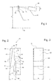
- the device comprises a light source such as laser diode 12 with upstream optics to impinge on a lens 14 preferably a cross-sectionally oval or elliptical beam whose optical axis 16 is inclined to the horizontal 18.
- the angle of inclination ⁇ is preferably approximately 2 °, without thereby limiting the teaching according to the invention.
- the laser beam, d. H. the optical axis 16 strikes the lens 14 at a distance A from the bottom surface 10 which is in the range of preferably 50 mm.
- the lens 14 is formed geometrically and aligned to the laser beam, ie to the optical axis 16 that corresponding representations of Fig. 4 and 5, both before and behind the lens 14 and thus the laser light source 12 on the bottom 10 a line becomes.
- the lens 14 has a cuboid geometry with a length L, a width B and a depth T. Exemplary dimensions are: 12 mm ⁇ L ⁇ 14 mm, 4 mm ⁇ B ⁇ 6 mm and 3 mm ⁇ T ⁇ 3.5 mm.
- the lens 14 has a front surface 20 and a rear surface 22 with respect to the light source 12. Furthermore, the lens 14 is subdivided into an upper first section 26 and a lower second section 28 by a projection 24 projecting above the rear side surface 22 and triangular in section.
- the rear side surface 22 further comprises two plane running Areas 34, 36, which merge into one another via a step 38. In this case, the upper region 26 in the active position of the lens 14 to the vertical angle ⁇ and the lower portion 28 an angle ⁇ , where ⁇ ⁇ .
- a recess 40 which has a groove-shaped geometry and parallel to the projection 24 and to the upper and lower boundary surfaces 30, 32 extends.
- the laser beam which preferably has an elliptical cross-section, wherein the large axis z. B. 3 mm to 5 mm and the small axis 1 mm to 1.5 mm may be smaller than the major axis, falls on the front side surface 20 of the lens 14, on the upper first portion 26.
- the optical axis 16 closes to the incident surface 42 an angle ⁇ with ⁇ ⁇ 90 °.
- the optical axis 16 should include an obtuse angle to the surface 40, namely the area extending to the head surface 30.
- the upper delimiting surface that is to say the top surface 30 of the lens 14
- the lower boundary surface ie bottom surface 32
- the lower boundary surface ie bottom surface 32
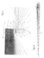
- the geometry of the lens 14, its design and alignment with the optical axis 16 in the operative position results in a refraction, reflection and fanning of the incident radiation according to FIGS. 4 and 5.
- the line shown on the bottom 10 extends to 10 m in front of the Lens 14.
- the running in the direction of the light source 12 portion of the optical marking has a length which extends beyond the light source 12, as the basic illustration of FIG. 5 can be seen.
- both the projection 24 and extending on the front side surface 20 recess 40 are essential for the Formation of the marking on the bottom surface 10.
- radiation at the respective transition region between the projection 24 and adjacent region of the rear side surface 22 is totally reflected (points 48, 50) to be reflected in the direction of the recess 40, in the further fanning of the radiation he follows.
- radiation from the inner surface of the step 38 is reflected back toward the light source 12 and into the region below it, respectively.
- a portion of the radiation totally reflected in the region 50 is totally reflected at the front side surface 20 below the recess 40 and refracted by the bottom surface 32 of the lens 14, so that the desired fanning of the radiation and thus the image of the line on the bottom surface 10 is ensured.
- the first or upper portion 26 of the lens 14 with the transverse side boundary surfaces decreasing in the direction of the head surface 30, ie, front and rear surfaces 20, 22, which are, as it were, boundaries of a wedge constituting the Lens 14 in the upper and lower portions 36 and 28 dividing projection 24 on the rear side surface 26 and extending in the lower portion 28 recess 40 in the front side surface 20th
Landscapes
- Physics & Mathematics (AREA)
- Engineering & Computer Science (AREA)
- General Physics & Mathematics (AREA)
- Radar, Positioning & Navigation (AREA)
- Remote Sensing (AREA)
- Lenses (AREA)
- Optical Radar Systems And Details Thereof (AREA)
Applications Claiming Priority (1)
| Application Number | Priority Date | Filing Date | Title |
|---|---|---|---|
| DE102006021421A DE102006021421A1 (de) | 2006-05-05 | 2006-05-05 | Vorrichtung und Verfahren zum Abbilden einer Markierung auf einer Begrenzung |
Publications (3)
| Publication Number | Publication Date |
|---|---|
| EP1852676A2 true EP1852676A2 (fr) | 2007-11-07 |
| EP1852676A3 EP1852676A3 (fr) | 2008-06-25 |
| EP1852676B1 EP1852676B1 (fr) | 2011-11-02 |
Family
ID=38372344
Family Applications (1)
| Application Number | Title | Priority Date | Filing Date |
|---|---|---|---|
| EP07107478A Active EP1852676B1 (fr) | 2006-05-05 | 2007-05-04 | Dispositif et procédé destinés à la représentation d'une marque sur une limite |
Country Status (5)
| Country | Link |
|---|---|
| US (1) | US7771074B2 (fr) |
| EP (1) | EP1852676B1 (fr) |
| CN (1) | CN101078625B (fr) |
| DE (1) | DE102006021421A1 (fr) |
| ES (1) | ES2376756T3 (fr) |
Families Citing this family (2)
| Publication number | Priority date | Publication date | Assignee | Title |
|---|---|---|---|---|
| GB2467470B (en) * | 2005-10-04 | 2010-10-06 | Comc Llc | Modular flooring assemblies |
| DE202007015265U1 (de) * | 2007-11-01 | 2009-03-12 | STABILA Messgeräte Gustav Ullrich GmbH | Anordnung zum Abbilden einer linienförmigen Markierung |
Family Cites Families (16)
| Publication number | Priority date | Publication date | Assignee | Title |
|---|---|---|---|---|
| US3984154A (en) * | 1973-12-21 | 1976-10-05 | Chin See L | Optical fan levelling system |
| DE4320177C2 (de) * | 1993-06-18 | 1996-04-04 | Laser Applikationan Gmbh | Optische Vorrichtung zur Erzeugung einer Linie und Verfahren zu ihrer Herstellung |
| DE19514626C2 (de) * | 1995-04-26 | 1997-03-06 | Fraunhofer Ges Forschung | Anordnung zur Formung des geometrischen Querschnitts eines Strahlungsfeldes eines oder mehrerer Festkörper- und/oder Halbleiterlaser(s) |
| JPH08339704A (ja) * | 1995-06-12 | 1996-12-24 | Nippondenso Co Ltd | 車両用灯具装置 |
| ES2138802T3 (es) * | 1995-09-26 | 2000-01-16 | Fiat Ricerche | Sistema de iluminacion con un microtelescopio incorporado en una placa transparente. |
| IT1281360B1 (it) * | 1995-09-26 | 1998-02-18 | Fiat Ricerche | Sistema di illuminazione a microtelescopio integrato in una lastra trasparente |
| DE29907156U1 (de) * | 1999-04-22 | 1999-08-12 | Z-Laser Optoelektronik GmbH, 79098 Freiburg | Vorrichtung zum Erzeugen einer optischen Markierung |
| DE19953114C2 (de) | 1999-11-04 | 2002-06-13 | Laser Optoelektronik Gmbh Z | Markiervorrichtung zum Projizieren einer optischen Hilfsmarkierung |
| US6502319B1 (en) * | 2000-10-04 | 2003-01-07 | Levelite Technology, Inc. | Apparatus for producing a visible line of light on a surface |
| EP1393016A4 (fr) * | 2001-05-15 | 2007-03-21 | American Tool Comp Inc | Dispositif de generation d'une ligne laser |
| JP3532167B2 (ja) | 2001-06-01 | 2004-05-31 | 株式会社オーディオテクニカ | レーザー墨出し器におけるレーザーライン光照射方法および装置 |
| JP3697690B2 (ja) * | 2001-09-20 | 2005-09-21 | 株式会社リズム | 基準用レーザライン照射のための合成樹脂製凹面コーンレンズ |
| US6914930B2 (en) * | 2002-05-31 | 2005-07-05 | Black & Decker Inc. | Laser level |
| JP2004094163A (ja) | 2002-09-04 | 2004-03-25 | Megafusion Corp | ネットワークサウンドシステムおよびサウンドサーバ |
| DE10344472A1 (de) * | 2003-09-25 | 2005-05-04 | Hilti Ag | Optischer Strahlteiler |
| DE202004007476U1 (de) * | 2004-03-26 | 2004-09-02 | Stabila-Meßgeräte Gustav Ullrich GmbH | Vorrichtung zum Abbilden einer linienförmigen optischen Markierung |
-
2006
- 2006-05-05 DE DE102006021421A patent/DE102006021421A1/de not_active Withdrawn
-
2007
- 2007-04-27 US US11/741,065 patent/US7771074B2/en active Active
- 2007-05-04 ES ES07107478T patent/ES2376756T3/es active Active
- 2007-05-04 EP EP07107478A patent/EP1852676B1/fr active Active
- 2007-05-08 CN CN2007101379886A patent/CN101078625B/zh active Active
Non-Patent Citations (1)
| Title |
|---|
| None |
Also Published As
| Publication number | Publication date |
|---|---|
| US20070262245A1 (en) | 2007-11-15 |
| CN101078625B (zh) | 2011-01-19 |
| DE102006021421A1 (de) | 2007-11-15 |
| EP1852676A3 (fr) | 2008-06-25 |
| ES2376756T3 (es) | 2012-03-16 |
| CN101078625A (zh) | 2007-11-28 |
| EP1852676B1 (fr) | 2011-11-02 |
| US7771074B2 (en) | 2010-08-10 |
Similar Documents
| Publication | Publication Date | Title |
|---|---|---|
| DE102008005488B4 (de) | Scheinwerfer für Fahrzeuge | |
| EP2469226A2 (fr) | Système optique pour la formation d'un rayonnement laser ainsi que système laser doté d'un tel système optique | |
| DE19743322A1 (de) | Laserstrahlformgebungssystem | |
| DE60015834T2 (de) | Lasergerät zur gleichzeitigen Erzeugung von mehreren zueinander senkrecht liegenden Laserebenen aus einer einzigen Laserquelle | |
| EP3653926A1 (fr) | Dispositif d'éclairage pour un phare de véhicule automobile ainsi que phare de véhicule automobile | |
| EP3242107A1 (fr) | Dispositif optique interférométrique de mesure d'une structure 3d d'un objet | |
| EP2469325A2 (fr) | Système optique pour la formation d'un rayonnement laser ainsi que système laser doté d'un tel système optique | |
| EP2056067B1 (fr) | Agencement destiné à représenter un marquage en forme de lignes | |
| EP3899358A1 (fr) | Dispositif d'éclairage pour un phare de véhicule automobile ainsi que phare de véhicule automobile | |
| EP1421415B1 (fr) | Systeme et dispositif d'homogeneisation de faisceau optique | |
| DE102007061358B4 (de) | Vorrichtung zur Formung von Laserstrahlung | |
| WO2021023743A1 (fr) | Film lumineux ayant une structure microoptique | |
| WO2015075188A1 (fr) | Élément optique et dispositif d'éclairage doté d'un élément optique | |
| DE10317958B4 (de) | Vorrichtung zum Erzeugen und Projizieren von Lichtmarken | |
| DE112006000841T5 (de) | Vorrichtung und Verfahren zum Prüfen der äußeren Erscheinung | |
| EP1852676B1 (fr) | Dispositif et procédé destinés à la représentation d'une marque sur une limite | |
| DE19941030C1 (de) | Laseranordnung für ein mehrstrahliges Laserrichtgerät | |
| DE102013114083B4 (de) | Vorrichtung zur Formung von Laserstrahlung | |
| EP1580526B1 (fr) | Dispositif de projection d'un repérage lumineux linéaire | |
| WO2019072633A1 (fr) | Dispositif optique pour un dispositif de mesure de distance selon le principe lidar | |
| DE102017125212B4 (de) | Linse und leuchtmodul | |
| EP1574880B1 (fr) | Emetteur pour barrière lumineuse, rideau optique ou équivalent | |
| EP2690398A1 (fr) | Dispositif de détermination de la position d'éléments mécaniques | |
| DE19820154A1 (de) | Vorrichtung und Verfahren zur optischen Strahltransformation | |
| EP2382493B1 (fr) | Dispositif et procédé de mesure sans contact d'une distance et/ou d'un profil |
Legal Events
| Date | Code | Title | Description |
|---|---|---|---|
| PUAI | Public reference made under article 153(3) epc to a published international application that has entered the european phase |
Free format text: ORIGINAL CODE: 0009012 |
|
| AK | Designated contracting states |
Kind code of ref document: A2 Designated state(s): AT BE BG CH CY CZ DE DK EE ES FI FR GB GR HU IE IS IT LI LT LU LV MC MT NL PL PT RO SE SI SK TR |
|
| AX | Request for extension of the european patent |
Extension state: AL BA HR MK YU |
|
| PUAL | Search report despatched |
Free format text: ORIGINAL CODE: 0009013 |
|
| AK | Designated contracting states |
Kind code of ref document: A3 Designated state(s): AT BE BG CH CY CZ DE DK EE ES FI FR GB GR HU IE IS IT LI LT LU LV MC MT NL PL PT RO SE SI SK TR |
|
| AX | Request for extension of the european patent |
Extension state: AL BA HR MK RS |
|
| 17P | Request for examination filed |
Effective date: 20080709 |
|
| AKX | Designation fees paid |
Designated state(s): DE ES FR GB IT |
|
| 17Q | First examination report despatched |
Effective date: 20100203 |
|
| GRAP | Despatch of communication of intention to grant a patent |
Free format text: ORIGINAL CODE: EPIDOSNIGR1 |
|
| GRAS | Grant fee paid |
Free format text: ORIGINAL CODE: EPIDOSNIGR3 |
|
| GRAA | (expected) grant |
Free format text: ORIGINAL CODE: 0009210 |
|
| RAP1 | Party data changed (applicant data changed or rights of an application transferred) |
Owner name: STABILA MESSGERAETE GUSTAV ULLRICH GMBH |
|
| AK | Designated contracting states |
Kind code of ref document: B1 Designated state(s): DE ES FR GB IT |
|
| REG | Reference to a national code |
Ref country code: GB Ref legal event code: FG4D Free format text: NOT ENGLISH |
|
| REG | Reference to a national code |
Ref country code: DE Ref legal event code: R096 Ref document number: 502007008580 Country of ref document: DE Effective date: 20120112 |
|
| REG | Reference to a national code |
Ref country code: ES Ref legal event code: FG2A Ref document number: 2376756 Country of ref document: ES Kind code of ref document: T3 Effective date: 20120316 |
|
| PLBE | No opposition filed within time limit |
Free format text: ORIGINAL CODE: 0009261 |
|
| STAA | Information on the status of an ep patent application or granted ep patent |
Free format text: STATUS: NO OPPOSITION FILED WITHIN TIME LIMIT |
|
| 26N | No opposition filed |
Effective date: 20120803 |
|
| REG | Reference to a national code |
Ref country code: DE Ref legal event code: R097 Ref document number: 502007008580 Country of ref document: DE Effective date: 20120803 |
|
| REG | Reference to a national code |
Ref country code: FR Ref legal event code: PLFP Year of fee payment: 10 |
|
| REG | Reference to a national code |
Ref country code: FR Ref legal event code: PLFP Year of fee payment: 11 |
|
| REG | Reference to a national code |
Ref country code: FR Ref legal event code: PLFP Year of fee payment: 12 |
|
| PGFP | Annual fee paid to national office [announced via postgrant information from national office to epo] |
Ref country code: ES Payment date: 20190620 Year of fee payment: 13 Ref country code: IT Payment date: 20190527 Year of fee payment: 13 |
|
| REG | Reference to a national code |
Ref country code: ES Ref legal event code: FD2A Effective date: 20210927 |
|
| PG25 | Lapsed in a contracting state [announced via postgrant information from national office to epo] |
Ref country code: IT Free format text: LAPSE BECAUSE OF NON-PAYMENT OF DUE FEES Effective date: 20200504 |
|
| PG25 | Lapsed in a contracting state [announced via postgrant information from national office to epo] |
Ref country code: ES Free format text: LAPSE BECAUSE OF NON-PAYMENT OF DUE FEES Effective date: 20200505 |
|
| P01 | Opt-out of the competence of the unified patent court (upc) registered |
Effective date: 20230528 |
|
| PGFP | Annual fee paid to national office [announced via postgrant information from national office to epo] |
Ref country code: DE Payment date: 20250516 Year of fee payment: 19 |
|
| PGFP | Annual fee paid to national office [announced via postgrant information from national office to epo] |
Ref country code: GB Payment date: 20250408 Year of fee payment: 19 |
|
| PGFP | Annual fee paid to national office [announced via postgrant information from national office to epo] |
Ref country code: FR Payment date: 20250528 Year of fee payment: 19 |