EP1852718A2 - Traitement NMR vers le bas - Google Patents
Traitement NMR vers le bas Download PDFInfo
- Publication number
- EP1852718A2 EP1852718A2 EP07014302A EP07014302A EP1852718A2 EP 1852718 A2 EP1852718 A2 EP 1852718A2 EP 07014302 A EP07014302 A EP 07014302A EP 07014302 A EP07014302 A EP 07014302A EP 1852718 A2 EP1852718 A2 EP 1852718A2
- Authority
- EP
- European Patent Office
- Prior art keywords
- measurements
- processor
- formation
- parameter
- sensor assembly
- Prior art date
- Legal status (The legal status is an assumption and is not a legal conclusion. Google has not performed a legal analysis and makes no representation as to the accuracy of the status listed.)
- Withdrawn
Links
- 238000012545 processing Methods 0.000 title description 28
- 230000015572 biosynthetic process Effects 0.000 claims abstract description 94
- 238000005553 drilling Methods 0.000 claims abstract description 63
- 239000012530 fluid Substances 0.000 claims abstract description 50
- 238000000034 method Methods 0.000 claims abstract description 48
- 230000033001 locomotion Effects 0.000 claims abstract description 45
- 238000002592 echocardiography Methods 0.000 claims abstract description 21
- 238000011156 evaluation Methods 0.000 claims abstract description 18
- 230000008569 process Effects 0.000 claims abstract description 8
- 238000005481 NMR spectroscopy Methods 0.000 claims description 88
- 238000005259 measurement Methods 0.000 claims description 82
- 238000012937 correction Methods 0.000 claims description 25
- 238000001208 nuclear magnetic resonance pulse sequence Methods 0.000 claims description 25
- XLYOFNOQVPJJNP-UHFFFAOYSA-N water Substances O XLYOFNOQVPJJNP-UHFFFAOYSA-N 0.000 claims description 16
- 238000003908 quality control method Methods 0.000 claims description 15
- 238000012935 Averaging Methods 0.000 claims description 12
- 230000004044 response Effects 0.000 claims description 9
- 239000004927 clay Substances 0.000 claims description 7
- 230000036961 partial effect Effects 0.000 claims description 7
- 230000035515 penetration Effects 0.000 claims description 7
- 230000001133 acceleration Effects 0.000 claims description 4
- 230000000149 penetrating effect Effects 0.000 claims description 3
- 230000035939 shock Effects 0.000 claims description 3
- 230000001419 dependent effect Effects 0.000 claims 1
- 238000005755 formation reaction Methods 0.000 description 62
- 238000000685 Carr-Purcell-Meiboom-Gill pulse sequence Methods 0.000 description 14
- 239000007789 gas Substances 0.000 description 10
- 238000004891 communication Methods 0.000 description 9
- 230000003068 static effect Effects 0.000 description 9
- UFHFLCQGNIYNRP-UHFFFAOYSA-N Hydrogen Chemical compound [H][H] UFHFLCQGNIYNRP-UHFFFAOYSA-N 0.000 description 8
- 230000000694 effects Effects 0.000 description 8
- 239000001257 hydrogen Substances 0.000 description 8
- 229910052739 hydrogen Inorganic materials 0.000 description 8
- 238000007781 pre-processing Methods 0.000 description 8
- 230000001960 triggered effect Effects 0.000 description 7
- 239000011435 rock Substances 0.000 description 6
- 230000035699 permeability Effects 0.000 description 5
- FAPWRFPIFSIZLT-UHFFFAOYSA-M Sodium chloride Chemical compound [Na+].[Cl-] FAPWRFPIFSIZLT-UHFFFAOYSA-M 0.000 description 4
- 238000009826 distribution Methods 0.000 description 4
- 230000001965 increasing effect Effects 0.000 description 4
- 239000011148 porous material Substances 0.000 description 4
- 238000001228 spectrum Methods 0.000 description 4
- 230000008901 benefit Effects 0.000 description 3
- 230000008859 change Effects 0.000 description 3
- 238000005520 cutting process Methods 0.000 description 3
- 230000009977 dual effect Effects 0.000 description 3
- 230000005251 gamma ray Effects 0.000 description 3
- 229930195733 hydrocarbon Natural products 0.000 description 3
- 150000002430 hydrocarbons Chemical class 0.000 description 3
- 238000012549 training Methods 0.000 description 3
- 238000004458 analytical method Methods 0.000 description 2
- 238000013528 artificial neural network Methods 0.000 description 2
- 230000005540 biological transmission Effects 0.000 description 2
- 230000015556 catabolic process Effects 0.000 description 2
- 239000000470 constituent Substances 0.000 description 2
- 230000003247 decreasing effect Effects 0.000 description 2
- 238000006731 degradation reaction Methods 0.000 description 2
- 238000002474 experimental method Methods 0.000 description 2
- 238000001914 filtration Methods 0.000 description 2
- 230000006870 function Effects 0.000 description 2
- 238000003672 processing method Methods 0.000 description 2
- 230000035945 sensitivity Effects 0.000 description 2
- 239000011780 sodium chloride Substances 0.000 description 2
- 239000007787 solid Substances 0.000 description 2
- 238000010200 validation analysis Methods 0.000 description 2
- 239000004215 Carbon black (E152) Substances 0.000 description 1
- 235000019738 Limestone Nutrition 0.000 description 1
- 235000015076 Shorea robusta Nutrition 0.000 description 1
- 244000166071 Shorea robusta Species 0.000 description 1
- 238000013459 approach Methods 0.000 description 1
- 238000004364 calculation method Methods 0.000 description 1
- 239000004020 conductor Substances 0.000 description 1
- 230000007423 decrease Effects 0.000 description 1
- 230000002950 deficient Effects 0.000 description 1
- 238000001739 density measurement Methods 0.000 description 1
- 238000009795 derivation Methods 0.000 description 1
- 238000010586 diagram Methods 0.000 description 1
- 238000006073 displacement reaction Methods 0.000 description 1
- 229910000514 dolomite Inorganic materials 0.000 description 1
- 239000010459 dolomite Substances 0.000 description 1
- 230000005284 excitation Effects 0.000 description 1
- 239000000706 filtrate Substances 0.000 description 1
- 239000008398 formation water Substances 0.000 description 1
- 125000004435 hydrogen atom Chemical group [H]* 0.000 description 1
- 230000006872 improvement Effects 0.000 description 1
- 230000001939 inductive effect Effects 0.000 description 1
- 230000000977 initiatory effect Effects 0.000 description 1
- 238000004519 manufacturing process Methods 0.000 description 1
- 239000011159 matrix material Substances 0.000 description 1
- 238000000691 measurement method Methods 0.000 description 1
- 238000012986 modification Methods 0.000 description 1
- 230000004048 modification Effects 0.000 description 1
- 238000012544 monitoring process Methods 0.000 description 1
- 230000001537 neural effect Effects 0.000 description 1
- 239000003129 oil well Substances 0.000 description 1
- 230000000737 periodic effect Effects 0.000 description 1
- 230000002093 peripheral effect Effects 0.000 description 1
- 239000003208 petroleum Substances 0.000 description 1
- 230000010287 polarization Effects 0.000 description 1
- 238000010223 real-time analysis Methods 0.000 description 1
- 230000002829 reductive effect Effects 0.000 description 1
- 230000002040 relaxant effect Effects 0.000 description 1
- 230000000284 resting effect Effects 0.000 description 1
- 238000012552 review Methods 0.000 description 1
- -1 salt ions Chemical class 0.000 description 1
- 238000005070 sampling Methods 0.000 description 1
- 239000004576 sand Substances 0.000 description 1
- 229920006395 saturated elastomer Polymers 0.000 description 1
- 238000007493 shaping process Methods 0.000 description 1
- 238000004904 shortening Methods 0.000 description 1
- 238000004088 simulation Methods 0.000 description 1
- 230000003595 spectral effect Effects 0.000 description 1
- 239000003381 stabilizer Substances 0.000 description 1
- 239000013589 supplement Substances 0.000 description 1
- 238000012546 transfer Methods 0.000 description 1
Images

Classifications
-
- E—FIXED CONSTRUCTIONS
- E21—EARTH OR ROCK DRILLING; MINING
- E21B—EARTH OR ROCK DRILLING; OBTAINING OIL, GAS, WATER, SOLUBLE OR MELTABLE MATERIALS OR A SLURRY OF MINERALS FROM WELLS
- E21B33/00—Sealing or packing boreholes or wells
- E21B33/10—Sealing or packing boreholes or wells in the borehole
- E21B33/12—Packers; Plugs
- E21B33/124—Units with longitudinally-spaced plugs for isolating the intermediate space
- E21B33/1243—Units with longitudinally-spaced plugs for isolating the intermediate space with inflatable sleeves
-
- E—FIXED CONSTRUCTIONS
- E21—EARTH OR ROCK DRILLING; MINING
- E21B—EARTH OR ROCK DRILLING; OBTAINING OIL, GAS, WATER, SOLUBLE OR MELTABLE MATERIALS OR A SLURRY OF MINERALS FROM WELLS
- E21B49/00—Testing the nature of borehole walls; Formation testing; Methods or apparatus for obtaining samples of soil or well fluids, specially adapted to earth drilling or wells
- E21B49/008—Testing the nature of borehole walls; Formation testing; Methods or apparatus for obtaining samples of soil or well fluids, specially adapted to earth drilling or wells by injection test; by analysing pressure variations in an injection or production test, e.g. for estimating the skin factor
-
- E—FIXED CONSTRUCTIONS
- E21—EARTH OR ROCK DRILLING; MINING
- E21B—EARTH OR ROCK DRILLING; OBTAINING OIL, GAS, WATER, SOLUBLE OR MELTABLE MATERIALS OR A SLURRY OF MINERALS FROM WELLS
- E21B49/00—Testing the nature of borehole walls; Formation testing; Methods or apparatus for obtaining samples of soil or well fluids, specially adapted to earth drilling or wells
- E21B49/02—Testing the nature of borehole walls; Formation testing; Methods or apparatus for obtaining samples of soil or well fluids, specially adapted to earth drilling or wells by mechanically taking samples of the soil
- E21B49/06—Testing the nature of borehole walls; Formation testing; Methods or apparatus for obtaining samples of soil or well fluids, specially adapted to earth drilling or wells by mechanically taking samples of the soil using side-wall drilling tools pressing or scrapers
-
- E—FIXED CONSTRUCTIONS
- E21—EARTH OR ROCK DRILLING; MINING
- E21B—EARTH OR ROCK DRILLING; OBTAINING OIL, GAS, WATER, SOLUBLE OR MELTABLE MATERIALS OR A SLURRY OF MINERALS FROM WELLS
- E21B49/00—Testing the nature of borehole walls; Formation testing; Methods or apparatus for obtaining samples of soil or well fluids, specially adapted to earth drilling or wells
- E21B49/08—Obtaining fluid samples or testing fluids, in boreholes or wells
- E21B49/10—Obtaining fluid samples or testing fluids, in boreholes or wells using side-wall fluid samplers or testers
-
- G—PHYSICS
- G01—MEASURING; TESTING
- G01V—GEOPHYSICS; GRAVITATIONAL MEASUREMENTS; DETECTING MASSES OR OBJECTS; TAGS
- G01V3/00—Electric or magnetic prospecting or detecting; Measuring magnetic field characteristics of the earth, e.g. declination, deviation
- G01V3/18—Electric or magnetic prospecting or detecting; Measuring magnetic field characteristics of the earth, e.g. declination, deviation specially adapted for well-logging
- G01V3/32—Electric or magnetic prospecting or detecting; Measuring magnetic field characteristics of the earth, e.g. declination, deviation specially adapted for well-logging operating with electron or nuclear magnetic resonance
-
- E—FIXED CONSTRUCTIONS
- E21—EARTH OR ROCK DRILLING; MINING
- E21B—EARTH OR ROCK DRILLING; OBTAINING OIL, GAS, WATER, SOLUBLE OR MELTABLE MATERIALS OR A SLURRY OF MINERALS FROM WELLS
- E21B2200/00—Special features related to earth drilling for obtaining oil, gas or water
- E21B2200/22—Fuzzy logic, artificial intelligence, neural networks or the like
Definitions
- This invention is related to methods for acquiring and processing nuclear magnetic resonance (NMR) measurements for determination of longitudinal and transverse relaxation times T 1 and T 2 .
- NMR nuclear magnetic resonance
- the invention deals with use of an expert system downhole for acquiring and evaluating NMR measurements contemporaneous with the drilling of wells and with use of a downlink communication from the surface for modifying the parameters of the downhole acquisition system.
- Nuclear magnetic resonance is used in the oil industry, among others, and particularly in certain oil well logging tools.
- NMR instruments may be used for determining, among other things, the fractional volume of pore space and the fractional volume of mobile fluid filling the pore space of earth formations. Methods of using NMR measurements for determining the fractional volume of pore space and the fractional volume of mobile fluids are described, for example, in " Spin Echo Magnetic Resonance Logging: Porosity and free Fluid Index Determination," M. N. Miller et al., Society of Petroleum Engineers paper no. 20561, Richardson, Tex., 1990 . Further description is provided in U.S. Pat. No. 5,585,720, of Carl M. Edwards, issued Dec. 17, 1996 and having the same assignee as the present application, entitled “Signal Processing Method For Multiexponentially Decaying Signals And Applications To Nuclear Magnetic Resonance Well Logging Tools.” The disclosure of that patent is incorporated herein by reference.
- T 2 relaxation spectra from nuclear magnetic resonance (NMR) data from logging subterranean formations, or from cores from such formations is critical to determining total and effective porosities, irreducible water saturations, and permeabilities of the formations.
- NMR nuclear magnetic resonance
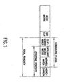
- U.S. Patent 6,069,477 to Chen et al having the same assignee as the present application discusses the constituents of a fluid saturated rock and various porosities of interest. Referring to Fig. 1, the solid portion of the rock is made up of two components, the rock matrix and dry clay. The total porosity as measured by a density logging tool is the difference between the total volume and the solid portion.
- the total porosity includes clay-bound water, capillary bound water, movable water and hydrocarbons.
- the effective porosity a quantity of interest to production engineers is the sum of the last three components and does not include the clay bound water. Accurate spectra are also essential to estimate T 2 cutoff values and to obtain coefficients for the film model or Spectral Bulk Volume Irreducible (SBVI) model. Effective porosities are typically summations of partial porosities, however, distortion of partial porosity distributions has been commonly observed for a variety of reasons. These reasons include poor signal-to-noise ratio (SNR), and poor resolution in the time domain of the NMR data.
- SNR signal-to-noise ratio
- the most common NMR log acquisition and core measurement method employs T 2 measurements using CPMG (Carr, Purcell, Meiboom and Gill) sequence, as taught by Meiboom and Gill in "Modified Spin-Echo Method for Measuring Nuclear Relaxation Time,” Rev. Sci. Instrum. 1958, 29, pp. 688-691 .
- CPMG Carr, Purcell, Meiboom and Gill
- TE interecho time
- wireline NMR logging tools used for obtaining information about earth formations and fluids after a wellbore has been drilled.
- the logging tools are lowered into the borehole and NMR signals are obtained using different configurations of magnets, transmitter coils and receiver coils.
- Rig time is expensive, so that the general objective in wireline logging is to obtain interpretable data within as short a time as possible.
- Rf radio frequency
- pulsing schemes for generating RF fields in the formation have been used,
- the most commonly used pulsing schemes are variations of the CPMG sequence.
- the parameters that may be varied are the wait time, the number of pulses within a CPMG sequence, and the time interval between the pulses.
- Tool vibration is usually not a problem in wireline logging, so that data may be acquired using continuous pulsing while the logging tool is being pulled up the borehole.
- other logs may already have been run before the NMR measurements are made, so that some preliminary evaluation of the subsurface formations may already exist. This makes it possible to use predefined pulse sequences optimized for specific evaluation objectives.
- the commonly used seven conductor wireline is not a serious limitation to two-way communication from the surface to the logging tool. This makes it possible to process data uphole with little or no downhole processing and to send instructions downhole to the logging tool to modify the acquisition schemes based on the surface processing.
- the sensitive volume of commonly used logging tools is no more than a few millimeters in thickness.
- the RF frequency is tuned to operate at the Larmor frequency corresponding to the static magnetic field in the sensitive volume, so that any transversal motion of the tool during drilling will mean that the RF pulses have a frequency corresponding to a region that has not been pre-polarized by the static magnetic field. This results in a severe degradation of the data.
- US Patent 5,705,927 issued to Kleinberg discloses making the length of each CPMG sequence small, e.g. 10 ms, so that the drill collar cannot be displaced by a significant fraction of the vertical or radial extent of the sensitive region during a CPMG pulse sequence. However using such short sequences and short wait times only gives an indication of the bound fluid volume and gives no indication of the total fluid volume.
- the present invention is an apparatus and method for acquiring NMR data of an earth formation using a sensor assembly conveyed on a measurement while drilling device in a borehole in the earth formation.
- the sensor assembly includes components on a non-rotating sleeve that may be clamped to the formation. With this arrangement, it is possible to continue drilling operations ("making hole") while making NMR pulse echo measurements at a fixed depth in the borehole and substantially isolated from vibrations caused by drilling.
- a downhole processor controls the acquisition and processing of the data.
- the processor controls the acquisition parameters based upon downhole motion sensors and also based upon control signals sent from the surface. Motion sensors such as accelerometers are used to monitor the motion of the sensor assembly and Quality control diagnostics are generated in real time.
- the processing includes standard processing methods.
- the basic pulse sequence is a CPMG sequence, although modified CPMG sequences with reduced power consumption may be employed.
- An expert system in the downhole processor also determines the lithology and fluid content of formations being drilled based on signals from other formation evaluation sensors such as gamma ray, neutron, resistivity and acoustic sensors .
- Information from a formation pressure tester (FPT) may also be used.
- the FPT provides measurements of formation pressure, mobility and compressibility of the fluid. Based upon this evaluation of the formation lithology and fluid content, the expert system may control the NMR acquisition parameters independently of surface control.
- measurements may be made in one of several modes. These include measurements while the NMR sensor assembly is clamped, measurements made when the NMR sensor assembly is rotating, measurements made when connecting (adding or removing drill segments at the surface) and measurements made while tripping (pulling the drillstring out of the borehole).
- the parameters of the pulse sequence that may be controlled include the wait time, the number of echos in a phase alternated pulse sequence, the number of repetitions of the phase alternated sequence, the tipping angle of the refocusing pulses, and the interecho spacing. Motion triggered pulsing may be used. In addition, the shape and bandwidth of the refocusing pulses may also be changed dynamically.
- FIG. 1 shows the different constituents of a fluid filled rock.
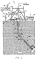
- Fig. 2 shows a schematic diagram of a drilling system 10 with a drillstring 20 carrying a drilling assembly 90 (also referred to as the bottom hole assembly, or "BHA") conveyed in a "wellbore" or “borehole” 26 for drilling the wellbore.
- the drilling system 10 includes a conventional derrick 11 erected on a floor 12 which supports a rotary table 14 that is rotated by a prime mover such as an electric motor (not shown) at a desired rotational speed.
- the drillstring 20 includes a tubing such as a drill pipe 22 or a coiled-tubing extending downward from the surface into the borehole 26. The drillstring 20 is pushed into the wellbore 26 when a drill pipe 22 is used as the tubing.
- a tubing injector such as an injector (not shown), however, is used to move the tubing from a source thereof, such as a reel (not shown), to the wellbore 26.
- the drill bit 50 attached to the end of the drillstring breaks up the geological formations when it is rotated to drill the borehole 26.
- the drillstring 20 is coupled to a drawworks 30 via a Kelly joint 21, swivel, 28 and line 29 through a pulley 23.
- the drawworks 30 is operated to control the weight on bit, which is an important parameter that affects the rate of penetration.
- the operation of the drawworks is well known in the art and is thus not described in detail herein.
- a suitable drilling fluid 31 from a mud pit (source) 32 is circulated under pressure through a channel in the drillstring 20 by a mud pump 34.
- the drilling fluid passes from the mud pump 34 into the drillstring 20 via a desurger 36, fluid line 28 and Kelly joint 21.
- the drilling fluid 31 is discharged at the borehole bottom 51 through an opening in the drill bit 50.
- the drilling fluid 31 circulates uphole through the annular space 27 between the drillstring 20 and the borehole, 26 and returns to the mud pit 32 via a return line 35.
- the drilling fluid acts to lubricate the drill bit 50 and to carry borehole cutting or chips away from the drill bit 50.
- a sensor S 1 preferably placed in the line 38 provides information about the fluid flow rate.
- a surface torque sensor S 2 and a sensor S 3 associated with the drillstring 20 respectively provide information about the torque and rotational speed of the drillstring.
- a sensor (not shown) associated with line 29 is used to provide the hook load of the drillstring 20.
- the drill bit 50 is rotated by only rotating the drill pipe 22.
- a downhole motor 55 (mud motor) is disposed in the drilling assembly 90 to rotate the drill bit 50 and the drill pipe 22 is rotated usually to supplement the rotational power, if required, and to effect changes in the drilling direction.
- the mud motor 55 is coupled to the drill bit 50 via a drive shaft (not shown) disposed in a bearing assembly 57.
- the mud motor rotates the drill bit 50 when the drilling fluid 31 passes through the mud motor 55 under pressure.
- the bearing assembly 57 supports the radial and axial forces of the drill bit.
- a stabilizer 58 coupled to the bearing assembly 57 acts as a centralizer for the lowermost portion of the mud motor assembly.
- a drilling sensor module 59 is placed near the drill bit 50.
- the drilling sensor module contains sensors, circuitry and processing software and algorithms relating to the dynamic drilling parameters. Such parameters preferably include bit bounce, stick-slip of the drilling assembly, backward rotation, torque, shocks, borehole and annulus pressure, acceleration measurements and other measurements of the drill bit condition.
- a suitable telemetry or communication sub 72 using, for example, two-way telemetry, is also provided as illustrated in the drilling assembly 100.
- the drilling sensor module processes the sensor information and transmits it to the surface control unit 40 via the telemetry system 72.
- the communication sub 72, a power unit 78 and an MWD tool 79 are all connected in tandem with the drillstring 20. Flex subs, for example, are used in connecting the MWD tool 79 in the drilling assembly 90. Such subs and tools form the bottom hole drilling assembly 90 between the drillstring 20 and the drill bit 50.
- the drilling assembly 90 makes various measurements including the pulsed nuclear magnetic resonance measurements while the borehole 26 is being drilled.
- the communication sub 72 obtains the signals and measurements and transfers the signals, using two-way telemetry, for example, to be processed on the surface. Alternatively, the signals can be processed using a downhole processor in the drilling assembly 90.
- the surface control unit or processor 40 also receives signals from other downhole sensors and devices and signals from sensors S 1 -S 3 and other sensors used in the system 10 and processes such signals according to programmed instructions provided to the surface control unit 40,
- the surface control unit 40 displays desired drilling parameters and other information on a display/monitor 42 utilized by an operator to control the drilling operations.
- the surface control unit 40 preferably includes a computer or a microprocessor-based processing system, memory for storing programs or models and data, a recorder for recording data, and other peripherals.
- the control unit 40 is preferably adapted to activate alarms 44 when certain unsafe or undesirable operating conditions occur.
- a suitable NMR device for use in the present invention is disclosed in US Patent 6,247,542 to Kruspe et al , the contents of which are fully incorporated herein by reference. This is show in Fig. 3.
- a segment 70 of drill pipe 22, illustrated in greater illustrates the apparatus and method according to Kruspe including a sleeve member, such as a sensor assembly, slidably coupled to a longitudinal member, such as a section of drill pipe, wherein, when the sleeve member is non-rotating, the longitudinal member is free to rotate.
- the sleeve member may be held in a non-rotating position through engagement with the borehole wall and a decoupling of the sleeve member and the rotating drillstring,
- the apparatus and method according to the present invention can be adapted for any MWD device or tool typically used on a rotating drillstring.
- the MWD tool 79 including an associated pulsed NMR tool 77 having a sensor assembly 113, and the pulsed power unit 78 are connected in tandem in the drilling assembly 90.
- the MWD tool 79 may also include a sonic sensor, a density measurement tool, and a porosity measurement tool.
- the NMR tool 77 is rotationally symmetric about a longitudinal axis 128 of the drilling assembly 100.
- the longitudinal member is, for example, a drill pipe section 101, which forms the core of the segment 70.
- the longitudinal member is a shaft in a downhole directional drilling assembly.
- the drill pipe section 101 is connected to the drillstring 20 by the upper tool joint 103 and the lower tool joint 139, and has a channel or flow pass 105 for the drilling mud to flow downhole.
- the sensor assembly 113 surrounds the drill pipe section 101 and is slidably coupled to the longitudinal member or the drill pipe section 101.
- the sensor assembly 113 is coupled to the drill pipe section 101 by at least one of guide sleeves 109 and 111.
- the guide sleeves 109 and 111 include, for instance, slip rings and bearings 110 and 112, respectively.
- a single guide sleeve (not shown) including slip rings and bearings, is used, for example, centrally located between ends of the sensor assembly 113.
- the guide sleeves 109 and 111 allow the sensor assembly 113 to move freely in the axial direction and to a lesser extent laterally with respect to the drill pipe section 101.
- the sensor assembly 113 has an outer diameter that is somewhat less than the inner diameter of the borehole 26.
- Fig. 3 shows the space between the sensor assembly 113 and the borehole wall in an exaggerated manner.
- the NMR sensor assembly includes flow paths 107 and 114 for return flow of the drilling mud from the drilling assembly 90 below wherein the gap between the sensor assembly 113 and the borehole wall are minimized.
- the magnet assembly 115, for providing the static magnetic field, and the RF coil assembly 117 are disposed in the sensor assembly 113.
- the RF coil assembly 117 includes, for instance, at least one transmitter for transmitting a pulsed RF field into the formation.
- the RF field is axial and is orthogonal to the static field of the permanent magnet assembly 115 in a region of interest or examination outside the borehole for NMR signal measurements.
- the apparatus of the present invention is not limited to the illustrated sensor assembly 113. Any number of appropriate magnet arrangements and antenna or coil arrangements which provide a static magnetic field and an RF field orthogonal to the static magnetic field direction for creating the region of interest for NMR signal sensitivity can be used according to the present invention.
- the NMR tool 77 can employ separate transmitter and receiver RF coils, located, for example, on the sensor assembly 113.
- the RF coil assembly 117 is pulsed and creates a high frequency electromagnetic RF field orthogonal to the static magnetic field generated by the magnet assembly 115 and in the region of substantially uniform field strength creating the region or volume of interest for NMR signal sensitivity.
- the sensor assembly 113 detects the NMR signals resulting therefrom.
- Rock pores in the earth formations surrounding the wellbore are filled with fluid, typically water or hydrocarbon.
- the hydrogen nuclei in the fluid are aligned by the region of homogeneous magnetic field, generated by the magnet assembly 115. The hydrogen nuclei are then flipped away from the homogeneous magnetic field by the pulsed RF field produced by RF coil assembly 117.
- the hydrogen nuclei revolve or precess at high frequency around the homogeneous magnetic field inducing an NMR signal in the RF coil assembly 117 until the hydrogen nuclei relax to the original direction along the homogeneous magnetic field.
- the induced NMR signals are processed downhole or sent to the surface for processing.
- the region of examination could have one of a number of configurations.
- the region of examination could be substantially toroidal shaped with the axis of the toroid along the longitudinal axis of the tool. In other configurations, the region of examination could be localized on opposite sides of the borehole or even on just one side of the borehole.
- the static magnetic field area can also be obtained if the magnet assembly 115 includes dc-energized electromagnets, or superconducting dc electromagnets. All of these are intended to be within the scope of the present invention.
- the NMR electronics 129 is housed in the NMR sensor assembly 113, The purpose of the NMR electronics 129 is to control the sensor assembly 113, record, process and transmit the recorded data, to the telemetry module 72. This can be done by means of electrical or acoustic telemetry by known devices and will not be discussed.
- a spring 130 having a cable conduit through the spring 130 allows power and data transmission via the guide sleeve 111 and slip ring through the cable conduit to and from the MWD tool 79.
- the MWD tool 79 also transmits data to the sensor assembly 113, for example, through mud pulse telemetry, and provides power from the power unit 78.
- the NMR electronics may also be referred to hereafter as a downhole processor, though it is to be understood that a downhole processor may be located at other positions in the downhole assembly.
- the sensor assembly 113 is also provided with at least one clamping pad, clamping piston or ribs 121.
- the ribs 121 are capable of outward movement for locking the sensor assembly 113 to the borehole wall during measurement by the sensor assembly 113.
- the ribs 121 are hydraulically activated. In the inactivated position of the ribs 121, the sensor assembly 113 rests on the lower tool joint 139 and is held up against gravitational pull by the spring 130 that is fixedly attached to the drill pipe section 101. Continued rotation of the drillstring 20 loosely carries the sensor assembly 113 along. In the activated position, the ribs 121 engage the borehole walls and prevent any further movement of the sensor assembly 113.
- the sensor assembly 113 is essentially decoupled from rotational and vertical movement of the drillstring 20, enabling measurements, such as NMR measurements from the NMR sensor assembly 113, to be carried out without interference from tool motion and vibration. Due to the proximity of the borehole wall to the magnet assembly 115, the region of examination is within the formation and any signal from the borehole fluid is small. In typical operation, the NMR measurement takes between 0.01 to 1 second, during which time the drill pipe section 101 advances some distance.
- the ribs 121 are retracted, as a result of which the sensor assembly 113 is no longer coupled to the borehole wall. The sensor assembly 113 then drops down until any further downward motion is stopped by the spring 130.
- the ribs 121 are actuated electrically, e.g., by a stepper motor. Other methods, such as those using springs, would be known to those versed in the art.
- the device of Kruspe thus comprises a sensor assembly mounted on a slidable sleeve slidably coupled to a longitudinal member, such as a section of drill pipe.
- a longitudinal member such as a section of drill pipe.
- the longitudinal member is free to rotate and continue drilling the borehole, wherein downhole measurements can be obtained with substantially no sensor movement or vibration. This is particularly useful in making NMR measurements due to their susceptibility to errors due caused by tool vibration.
- a clamping device is used, for instance, to hold the sensor assembly is held in the non-rotating position.
- the specific NMR sensor discloses in Kruspe et al has permanent magnets as well as RF antennas on the sleeve.
- a suitable sensor configuration is disclosed in U.S. Patent 6,215,304 to Slade , the contents of which are fully incorporated herein by reference.
- the tool is rotationally symmetric, i.e., it measures 360° around the tool simultaneously.
- other magnet and antenna configurations could be used.
- An advantage of using the Slade device is that usually no borehole correction is necessary because the tool is tuned to read only formation signal unless the hole is severely enlarged or the tool is off center.
- a thruster allows compensation for the axial drillstring movement during the acquisition. This is provides the tool with a great deal of flexibility in acquisition of NMR data. Specifically, four modes of operation are possible with the tool:
- the sensor assembly In the clamped mode of operation, the sensor assembly is clamped to the borehole and is thus substantially decoupled from motion of the drillbit and vibration of the bottom hole assembly.
- data acquisition in the clamped mode may be carried out for several minutes. This makes it possible to acquire data with long pulse sequences with enhanced signal to noise ratio (SNR).
- SNR signal to noise ratio
- the sensor assembly In the rotating mode, the sensor assembly is rotating at a rate that could be almost as rapid as the rotation of the drilling tubular.
- the rotation by itself does not degrade the quality of data acquired by the sensor assembly due to the complete rotational symmetry of the region of examination of the tool.
- due to tool vibration (transverse and vertical) and whirl, data quality may be degraded. This arises from the fact that the region of examination is relatively small so that pulse echo signals may arise from regions of the formation that are only partially polarized by the permanent magnets.
- Hawkes et al teach the use of motion triggered pulsing for NMR measurements.
- the motion of the tool is measured by suitable motion sensors, such as accelerometers, magnetometers or gyroscopes or combinations thereof. These sensors may be placed at any suitable location on the drilling tool in the proximity of the magnet and coil arrangement.
- the wait period in a pulse sequence may be extended slightly without affecting the data quality and this feature may be used to delay the application of the tipping pulse until a suitable state of tool motion is achieved.
- the trigger may be obtained by monitoring the motion sensor signals. Suitable states for triggering are instantaneous moments when the tool is stationary, or if the motion has a strong periodic component, then subsequent pulse sequences may be triggered to synchronize with this motion. Such motion triggered pulsing will improve the NMR spin-echo formation. Hawkes also teaches the use of predictive filtering, such as Kalman filtering, for initiating the tipping pulse that is commonly used in a CPMG pulse sequence. This too may be used in the method of the present invention.
- predictive filtering such as Kalman filtering
- the length of the pulse sequences used in analysis of the formation would be controlled at least in part by the ROP. At low ROP, it is possible to use long pulse sequences to improve the SNR without loss of resolution. As always, the available power is a limitation and an optional embodiment of the present invention may use the modified CPMG sequence taught in US Patent 6 163 153 by Reiderman et al with a shortened refocusing pulse.
- the drillbit In the changing mode, the drillbit is non-rotating and the drillstring is clamped at the surface while additional sections of drill pipe are added or removed. However, due to the elasticity of the drillstring, vertical and transverse vibrations continue. The total acquisition time is usually limited to less than sixty seconds. Again, the motion triggered pulsing scheme of Hawkes et al may be used, and with better results than in the rotating mode. The improvement arises from the fact that the entire drillstring may be vibrating freely without additional stresses and whirl caused as the drillbit "makes hole.”
- the axial tool motion is quite rapid.
- three sections of drillstring (a total of 90 ft.) are pulled at a time, after which the drillstring is clamped at the surface (at which time acquisition in the changing mode is possible).
- correction has to be made for the change in the sensitive volume during a pulse sequence.
- this is a simple geometric correction factor based upon the nominal velocity of tool motion as measured at the surface.
- accelerometers on or near the NMR sensor make measurements of the axial acceleration of the NMR sensor. The actual velocity of tool motion is determined from the accelerometer measurements and used to derive the correction factor.
- the standard data acquisition and processing scheme uses methods that have been used in wireline logging.
- the acquisition and processing parameters for this are stored in the memory of the downhole processor and are described below.
- the downhole processor also includes an expert system that analyzes data acquired by the NMR sensor assembly and one or more additional sensors, including formation sensors and sensors indicative of drilling conditions as discussed above.
- the expert system modifies the acquisition and processing schemes used for the NMR data. This may be done independently of the surface processor 40 or may be done in response to downlink commands from the surface processor 40 through the communication sub 72.
- Such a downlink telemetry system is taught in European Patent 744,527 of Oppelt et al and United States Patent 5,963,138 of Gruenhagen et al , having the same assignee as the present application.
- One pre-processing step that is routinely carried out is replacement of invalid data.
- QC Quality Control
- Recognition of invalid data is based on adequate diagnostics.
- These diagnostics are provided by the motion sensors discussed in the Hawkes application. Even in the clamped mode of acquisition, it is preferable to do the clamping at a time when the motion of the drill collar is small. While this is not a guarantee that good data will be acquired when clamped, it does provide some insurance.
- motion triggered pulsing is highly desirable. However, analysis of the data after acquisition may still require that all data of one acquisition cycle be discarded.
- diagnostics data have to be acquired and evaluated parallel to the NMR acquisition (e.g., hardware performance, vibration data). If these data are not available, the data quality can be indicated with real-time analysis of the sum of echos (SE) as discussed below.
- SE sum of echos
- phase here refers to phase alternated pulse sequences in the data acquisition as used in the art.
- channel refers to the fact that NMR echo signals are acquired in two channels that are in-phase and in quadrature to the RF carrier phase.
- Another aspect of the present standard preprocessing in the present invention is that based on the echo shape and the overlying noise (white noise plus non-random ringing) several methods can be used for echo point averaging with different purposes,
- One simple method to average echo points is linear averaging of the data in the whole acquired echo window.
- An alternate embodiment of the invention uses weighted averaging of the data, where the weighting is fixed (e.g., cosine function) or determined in lab and field experiments (e.g., expected shape of the echo signal to maximize signal-to-noise ratio). These windows are centered on a peak value of the measured echo signal and provide some discrimination against random noise.
- Another preprocessing step in the invention uses sums of individual echo trains as a quality control (QC) indicator.
- QC quality control
- US Patent Application Ser. No. 091483,336 to Chen discusses the use of summed echo trains as a QC indicator and is incorporated herein by reference.
- sums of individual echo trains at a clamped depth are used to determine the quality of the data.
- the standard preprocessing preferably includes the so-called phase alternated pulse (PAP) sequence.
- Successive CPMG or modified CPMG sequences are acquired with alternating phases of the tipping pulse.
- the -90° x and +90° x data are either subtracted or added to eliminate constant offset of the echo channel data.
- a corrected acquisition time for the combined data has to be calculated (e.g. for PAP data calculate mean acquisition time of the two echo trains)
- no PAP averaging is done.
- the preprocessing also includes a correction for stimulated echo effects.
- the stimulated echo effects arise from imperfect tipping and refocusing pulses. Evan a small gradient field makes it impossible to create a perfect pulse that will rotate protons in the sample space exactly the desired angle (e.g. 180°) and not rotate protons "near" the sample space that are off resonance.
- the calibration of the tool in a known environment allows these effects to be determined and correction equations derived. As a result of the imperfect pulses, the first few echoes do not fit the rest of the echoes and need to be scaled by a correction factor.
- STE n is determined by lab or field experiments or by simulation results. As would be known to those versed in the art, STE n depends upon B 1 and the operating temperature. It may also depend upon the tipping and refocusing angles and the bandwidth of the transmitter and receiver.
- the signals measured in the two channels E x and E y have amplitudes E xn and E yn respectively.
- a calibration factor is used to convert measured echo signals to signal amplitudes in porosity units (p.u.). Measurements are taken in an environment with known porosity and where a single decay component of the fluid is expected.
- the calibration procedure includes:
- the salinity correction factor is multiplied to the echo data for compensation.
- the petrophysical processing of the echo data typically includes a correction for salinity.
- the salinity of the fluid in the tool's sensitive region can be approximated by the formation fluid salinity or, in case of an invaded formation, by the salinity of the mud filtrate. No salinity correction is necessary if the formation is mainly oil filled or if the resistivity of the formation fluid > 10 ⁇ m at 75°F.
- SE provides QC information used as discussed above in [0031]. SE also provides petrophysical information such as a high resolution permeability estimation. Such a method is disclosed in Sezinger et al., "High Resolution Permeability Indicator" presented at the 1999, SPWLA Annual Conferences and Exhibition, Oslo, Norway, June 1999 .
- Stacking of the data may be performed to increase SNR.
- this includes averaging of all data from one clamping cycle.
- this includes averaging of all data from one resting cycle.
- this includes windowed averaging of data over a plurality NL levels. Typically, in the tripping mode, data from up to 4 levels are averaged.
- the downhole processor includes a program that determines the porosity of the formation and the irreducible water saturation (BVI).
- the irreducible water saturation, BVI is calculated by weighted contributions of the partial porosities in reference to a given cutoff value, T 2c .
- Porosity can also be measured by additional sensors (e.g, density, accoustic, neutron etc.) and can be compared with those measurements on a realtime basis.
- FTM Formation Temperature Multiplier
- HDM Hydrogen Depletion Multiplier
- the downhole processor when standard processing is used, sends processed data to the surface processor using the telemetry sub 72. Due to the limited transmission capability of the telemetry channel, the data that are sent up are limited. Typically, they include the total porosity N , the BVI, the sum of echos SE, and the level ⁇ N . Additional QC indicators that may be sent include the signals indicative of the motion of the tool. This is in addition to other formation evaluation data that may be sent uphole. These may include processed or unprocessed data from gamma ray tools, neutron logging tools, density tools and resistivity tools. Such devices would be known to those versed in the art and are not discussed here further.
- the operator at the surface has access to the data sent from the telemetry sub 72 and they are processed and/or displayed by the surface control unit 40. Based upon this, the operator can evaluate the drilling conditions, make judgments about the lithology and formation fluid being drilled and evaluate the quality of the data (specifically including the NMR data). Based upon this evaluation, the operator may send instructions downhole that alter the acquisition parameters being used for the NMR data. This is done on a real-time basis in the drilling or clamping mode. It may also be done in the connecting mode and the tripping mode with less effectiveness. The reasons for the lowered effectiveness of altering the acquisition parameters is that in the tripping mode, the bottom hole assembly generally has a fairly rapid motion that may encompass several different lithologies and fluid types. The acquisition parameters that my be controlled are discussed next.
- a CPMG sequence may be represented as [ TW i - 90 ⁇ ⁇ / 2 - ( ⁇ - X - ⁇ - echo ⁇ ) j ] i
- TW is a wait time
- 90 ⁇ B/2 refers to a phase alternated 90° tipping pulse
- X is a refocusing pulse with a tipping angle that lies between 90° and 180°
- j is the number of echos observed
- 2 ⁇ is an interecho spacing.
- the basic sequence within the square bracket may be repeated i times with different wait times and the whole sequence denoted by eq. (12) may be repeated at a single clamp position a plurality of times to improve the SNR
- the number of repetitions is less than in the clamped mode.
- the downhole processor has the capability of adjusting any of the parameters in the pulse sequence given by eq. (12). As noted above, in one embodiment of the invention, these changes are made by the operator at the surface using a downlink capability. The effects of changes in the parameters are discussed next.
- the simplest parameter that may be controlled is the number of repetitions i in eq. (12).
- the primary use of this is to improve the SNR and make use of the stacking capability discussed above.
- the selection of this is determined primarily by the vibration of the tool and the accompanying degradation of the echo signals. In the clamped mode, this may be selected to be as large as necessary since there is no axial tool motion. In the connect mode, even though there is no axial movement of the drillstring at the surface, due to the elasticity of the drillstring, there may be axial movement of the NMR sensor assembly at depth. Obviously, in the tripping mode, the number of repetitions can be increased only at the cost of loss of resolution.
- the loss of resolution with a large choice of i depends upon the rate of penetration ROP: in hard limestones and dolomite rocks, the ROP is small and hence more repetitions can be done, while in soft shales and soft sandstones, the number of repetitions would be less,
- the wait time TW can also be changed.
- the effect of changing the wait time is to change the amount of polarization of the nuclear spins between successive CPMG sequences produced by the static magnetic field.
- long wait times are required to fully polarize the hydrogen nuclei. This would appear to make it necessary to acquire data with long wait times to provide an estimate of gas saturation.
- wait times of several seconds are possible. However, estimates of gas saturation may also be obtained using shorter wait times. This is discussed in copending US Patent Application Ser. No. 09/396,286 of Thern et al , the contents of which are fully incorporated herein by reference.
- Thern teaches the use of a dual wait time data wherein the formation water is substantially fully polarized at both wait times while the gas component experiences a different partial saturation for the two wait times.
- the method of Thern may be used at normal logging speeds and is hence also suitable for measurements in the drilling mode and in the connect mode. It may also be used with less effectiveness in the tripping mode.
- a first plurality of short pulse sequences (small values of j ) are acquired followed by a second plurality of longer pulse sequences (larger values of j ) wherein the second plurality i is less than the first plurality i .
- a series of short pulse sequences are acquired with a small value of ⁇ followed by one or more regular (long) pulse sequences with a longer value of ⁇ .
- the short pulse sequences with the small value of ⁇ make it possible to determine the CBW of the formation while the long pulse sequence is used for obtaining the slowly relaxing components.
- data are acquired with a variable ⁇ within a single sequence as taught in an application entitled ''NMR Data Acquisition with Multiple Interecho Spacing" filed under Attorney Docket No, 414-26580 on June 28,2001, the contents of which are fully incorporated herein be reference.
- Another acquisition parameter that can be controlled is the length and shape of the refocusing pulse.
- the Reiderman patent discusses the advantage of shortening the tipping angle of the refocusing pulse for conserving power.
- the shape of the refocusing pulse may also be changed.
- Co-pending US Patent Application Ser. No. 09/606,998 of Beard et al having the same assignee as the present application and the contents of which are fully incorporated herein by reference, discusses the effect of pulse shaping in a multi-frequency NMR tool for reducing the interference between pulse sequences at different RF frequencies.
- the excitation and refocusing pulses need not be square waves in the time domain.
- the teachings of Beard et al are also applicable in that the even for a single frequency tool, it is desirable to match the bandwidth of the 90° pulse with the bandwidth of the refocusing pulses.
- Another novel feature of the present invention is the implementation of an Expert System in the downhole processor for control of the acquisition parameters.
- the Expert System adjusts the acquisition parameters from the NMR data alone.
- the Expert System may compare the QC indicators, such as the sum of echos at different levels. If outliers are detected, a warning signal is sent uphole.
- the Expert System analyzes the acquired NMR data and from this, the pulse sequences may be shortened or lengthened (both i and j in eq. (12)) and the ⁇ and TW may be adjusted as discussed above. This may be based upon the determined porosity and T 2 spectrum characteristics such as BVI, BVM (bound water movable), the geometric mean of the T 2 distribution, the main peaks of the T 2 distribution.
- BVI porosity
- BVM bound water movable
- the Expert System also has access to measurements made by other sensors described above with reference to Fig. 2. These may relate to drilling conditions or to the formation properties.
- sensors relating to drilling conditions i.e., the accelerometer measurements
- accelerometer measurements has already been discussed above with respect to motion triggered pulsing. If the downhole conditions are changing, the acquisition and processing parameters are changed accordingly.
- the other formation evaluation sensors be located between the NMR sensors and the drillbit.
- the FPT gives an estimate of fluid mobility (defined as the ratio of permeability to viscosity). This, when combined with the NMR-determined permeability gives the fluid viscosity.
- FPT is also evaluating the fluid type - an information which can be used for NMR MWD again If the preferred arrangement (other formation evaluation sensors located between the NMR sensors and the drill bit) is not used, then the Expert System changes the NMR acquisition parameters based upon predicted stratigraphy.
- gamma rays measurements may be used to determine the shale content of the formation at the depth of the NMR sensors, In a shaly interval, short pulse sequences and small values of 9 are sufficient.
- the presence of hydrocarbons in the formation is diagnosed from resistivity measurements.
- the presence of gas in the formation may be indicated by acoustic log measurements.
- even a small amount of gas in the formation significantly lowers the P-wave velocity in a porous sand formation and additional changes in P-wave velocity changes are only slightly affected by the amount of gas present. In such a situation, it is desirable to use a dual wait time acquisition and processing to determine the gas saturation.
- the Expert System is preferably implemented using neural networks (NNs).
- NNs neural networks
- more than one NN is used.
- a first NN is used for determination of lithology and formation fluid type from formation property measurements.
- a second NN is used for modifying the NMR acquisition and processing parameters based upon the knowledge of the lithology and fluid type and the drilling conditions. These are discussed separately.
- the first NN that is used for lithology and fluid determination has as its input measurements from formation evaluation sensors. As noted above, these can include resisitivity, acoustic, gamma ray, density and neutron sensors. Based upon these sensor outputs, the lithology and fluid content of the formation can be determined by a human.
- a NN implementation of the lithology/fluid identification involves changing the parameters of the NN to provide a match with the evaluation made by a human expert.
- the second NN that is used in the present invention has its inputs the lithology/fluid content of the formation and the output of drilling condition sensors. These inputs are used to modify the NMR acquisition parameters. Once again, the objective is to determine the parameters of this second NN that match those of a human expert.
- the first step is the training of the NN. Required for this is a wide statistical sampling of input parameters and the corresponding decision of a human expert.
- the second step is the validation of the NN; in the validation process, samples that are different from those used in the training process are input to the NN and the decision of the NN is again compared with that of the human expert. If there is agreement, then the NN has been validated.
- the NN Once the NN has been validated, its structure and parameters may be stored in the processor and NN may then be used to process, preferably in real time, measurements made by the logging device.
- the Stuttgart Neural Net Simulator is used for the training of the NN.
Landscapes
- Life Sciences & Earth Sciences (AREA)
- Engineering & Computer Science (AREA)
- Geology (AREA)
- Mining & Mineral Resources (AREA)
- Physics & Mathematics (AREA)
- General Life Sciences & Earth Sciences (AREA)
- Environmental & Geological Engineering (AREA)
- Geochemistry & Mineralogy (AREA)
- Fluid Mechanics (AREA)
- Soil Sciences (AREA)
- Chemical & Material Sciences (AREA)
- Analytical Chemistry (AREA)
- High Energy & Nuclear Physics (AREA)
- Remote Sensing (AREA)
- General Physics & Mathematics (AREA)
- Geophysics (AREA)
- Geophysics And Detection Of Objects (AREA)
Applications Claiming Priority (2)
| Application Number | Priority Date | Filing Date | Title |
|---|---|---|---|
| US09/928,768 US6727696B2 (en) | 1998-03-06 | 2001-08-13 | Downhole NMR processing |
| EP02773186A EP1425613A1 (fr) | 2001-08-13 | 2002-08-13 | Traitement de donnees de mesure en resonance magnetique nucleaire (rmn) pour fond de puits |
Related Parent Applications (1)
| Application Number | Title | Priority Date | Filing Date |
|---|---|---|---|
| EP02773186A Division EP1425613A1 (fr) | 2001-08-13 | 2002-08-13 | Traitement de donnees de mesure en resonance magnetique nucleaire (rmn) pour fond de puits |
Publications (1)
| Publication Number | Publication Date |
|---|---|
| EP1852718A2 true EP1852718A2 (fr) | 2007-11-07 |
Family
ID=25456720
Family Applications (2)
| Application Number | Title | Priority Date | Filing Date |
|---|---|---|---|
| EP02773186A Withdrawn EP1425613A1 (fr) | 2001-08-13 | 2002-08-13 | Traitement de donnees de mesure en resonance magnetique nucleaire (rmn) pour fond de puits |
| EP07014302A Withdrawn EP1852718A2 (fr) | 2001-08-13 | 2002-08-13 | Traitement NMR vers le bas |
Family Applications Before (1)
| Application Number | Title | Priority Date | Filing Date |
|---|---|---|---|
| EP02773186A Withdrawn EP1425613A1 (fr) | 2001-08-13 | 2002-08-13 | Traitement de donnees de mesure en resonance magnetique nucleaire (rmn) pour fond de puits |
Country Status (5)
| Country | Link |
|---|---|
| US (2) | US6727696B2 (fr) |
| EP (2) | EP1425613A1 (fr) |
| CA (1) | CA2457672C (fr) |
| NO (1) | NO334292B1 (fr) |
| WO (1) | WO2003016953A1 (fr) |
Cited By (3)
| Publication number | Priority date | Publication date | Assignee | Title |
|---|---|---|---|---|
| WO2013081775A1 (fr) * | 2011-11-30 | 2013-06-06 | Halliburton Energy Services, Inc. | Utilisation de mesures de pression de fond de puits pendant le forage permettant de détecter et de mitiger les afflux |
| US11175430B1 (en) | 2020-05-19 | 2021-11-16 | Halliburton Energy Services, Inc. | Processing nuclear magnetic resonance signals in a downhole environment |
| US11573348B1 (en) | 2022-01-26 | 2023-02-07 | Saudi Arabian Oil Company | Method and system using nuclear magnetic resonance well logging for T2 cutoff value estimation |
Families Citing this family (70)
| Publication number | Priority date | Publication date | Assignee | Title |
|---|---|---|---|---|
| US6727696B2 (en) * | 1998-03-06 | 2004-04-27 | Baker Hughes Incorporated | Downhole NMR processing |
| US6247542B1 (en) * | 1998-03-06 | 2001-06-19 | Baker Hughes Incorporated | Non-rotating sensor assembly for measurement-while-drilling applications |
| US6977499B2 (en) * | 1999-02-09 | 2005-12-20 | Baker Hughes Incorporated | Formation-based interpretation of NMR data for carbonate reservoirs |
| US7301338B2 (en) * | 2001-08-13 | 2007-11-27 | Baker Hughes Incorporated | Automatic adjustment of NMR pulse sequence to optimize SNR based on real time analysis |
| US7016026B2 (en) * | 2002-04-10 | 2006-03-21 | Baker Hughes Incorporated | Method and apparatus for a downhole refractometer and attenuated reflectance spectrometer |
| DE60215963T2 (de) * | 2002-12-31 | 2007-08-02 | Schlumberger Technology B.V. | Verfahren und Vorrichtung zur spektroskopischen Verarbeitung von Daten im Bohrloch |
| US7027922B2 (en) * | 2003-08-25 | 2006-04-11 | Baker Hughes Incorporated | Deep resistivity transient method for MWD applications using asymptotic filtering |
| US7043370B2 (en) * | 2003-08-29 | 2006-05-09 | Baker Hughes Incorporated | Real time processing of multicomponent induction tool data in highly deviated and horizontal wells |
| US7268547B2 (en) * | 2003-10-07 | 2007-09-11 | Baker Hughes Incorporated | Correction of motion influences in NMR signals |
| US7091719B2 (en) * | 2004-04-30 | 2006-08-15 | Schlumberger Technology Corporation | Method for determining properties of formation fluids |
| US7268552B1 (en) * | 2004-06-21 | 2007-09-11 | United States Of America As Represented By The United States Department Of Energy | Capillary toroid cavity detector for high pressure NMR |
| US7196516B2 (en) * | 2004-08-16 | 2007-03-27 | Baker Hughes Incorporated | Correction of NMR artifacts due to constant-velocity axial motion and spin-lattice relaxation |
| US7168310B2 (en) * | 2004-08-26 | 2007-01-30 | Saudi Aramco | Accuracy of shaly sand formation evaluation |
| US7650269B2 (en) * | 2004-11-15 | 2010-01-19 | Halliburton Energy Services, Inc. | Method and apparatus for surveying a borehole with a rotating sensor package |
| GB2438121B (en) * | 2005-02-19 | 2010-11-17 | Baker Hughes Inc | Use of the dynamic downhole measurements as lithology indicators |
| WO2006093492A2 (fr) * | 2005-02-28 | 2006-09-08 | Kerr-Mcgee Rocky Mountain Llc | Procede de diagraphie directe de permeabilite d'une formation souterraine |
| US7363161B2 (en) * | 2005-06-03 | 2008-04-22 | Baker Hughes Incorporated | Pore-scale geometric models for interpretation of downhole formation evaluation data |
| US7298142B2 (en) * | 2005-06-27 | 2007-11-20 | Baker Hughes Incorporated | Method and apparatus for reservoir fluid characterization in nuclear magnetic resonance logging |
| US7425827B2 (en) | 2005-10-03 | 2008-09-16 | Baker Hughes Incorporated | Method and apparatus for formation evaluation and borehole size determination |
| EP1795921B1 (fr) * | 2005-12-06 | 2013-01-23 | Services Petroliers Schlumberger | Détermination de la porosité et la saturation du fluide dans des formations souterraines. |
| US7413034B2 (en) * | 2006-04-07 | 2008-08-19 | Halliburton Energy Services, Inc. | Steering tool |
| BRPI0621711A2 (pt) * | 2006-06-06 | 2012-09-18 | Halliburton Energy Serv Inc | aparelho, sistema e método para tipificação de fluido, e, meio legìvel por computador |
| US7665544B2 (en) * | 2006-12-05 | 2010-02-23 | Baker Hughes Incorporated | Method to improve downhole instruments |
| ATE472110T1 (de) * | 2007-01-12 | 2010-07-15 | Koninkl Philips Electronics Nv | Sensoreinrichtung und verfahren zur erfassung von magnetischen teilchen |
| EP2084559A4 (fr) * | 2007-01-18 | 2011-04-13 | Halliburton Energy Serv Inc | Inversion simultanee de temps de relaxation |
| DE102008008602B4 (de) | 2007-06-22 | 2018-03-29 | Siemens Aktiengesellschaft | Transfervorrichtung für Werkstückträger sowie Verfahren zum Transportieren von Werkstückträgern |
| US8073623B2 (en) * | 2008-01-04 | 2011-12-06 | Baker Hughes Incorporated | System and method for real-time quality control for downhole logging devices |
| US8324895B2 (en) * | 2009-01-23 | 2012-12-04 | Baker Hughes Incorporated | MWD/LWD NMR imaging with long echo trains |
| US8373412B2 (en) * | 2009-01-23 | 2013-02-12 | Baker Hughes Incorporated | NMR-LWD imaging tool |
| US8604783B2 (en) * | 2009-05-08 | 2013-12-10 | Baker Hughes Incorporated | Method and apparatus for NMR measurements while drilling with multiple depths of investigation |
| WO2010151252A1 (fr) | 2009-06-24 | 2010-12-29 | Halliburton Energy Services, Inc. | Systèmes et procédés pour améliorer des images de données diagraphiques |
| US20110108325A1 (en) * | 2009-11-11 | 2011-05-12 | Baker Hughes Incorporated | Integrating Multiple Data Sources for Drilling Applications |
| US20110172922A1 (en) * | 2010-01-11 | 2011-07-14 | Baker Hughes Incorporated | Drop/Pump Memory Through-Casing Measurement Logging Tools |
| US8836328B2 (en) * | 2010-02-03 | 2014-09-16 | Baker Hughes Incorporated | Acoustic excitation with NMR pulse |
| US8820144B2 (en) | 2010-06-06 | 2014-09-02 | International Environmental Technologies, Inc. | Apparatus and method for fluid monitoring |
| US8669516B2 (en) | 2010-08-20 | 2014-03-11 | Baker Hughes Incorporated | Using LWT service to identify loss circulation areas in a wellbore |
| US10253612B2 (en) | 2010-10-27 | 2019-04-09 | Baker Hughes, A Ge Company, Llc | Drilling control system and method |
| US8860413B2 (en) * | 2010-11-19 | 2014-10-14 | Schlumberger Technology Corporation | Nuclear magnetic resonance tool with movable magnets |
| US9335195B2 (en) * | 2011-02-16 | 2016-05-10 | Baker Hughes Incorporated | Multiphase meter to provide data for production management |
| US8967248B2 (en) * | 2011-08-23 | 2015-03-03 | Harris Corporation | Method for hydrocarbon resource recovery including actuator operated positioning of an RF sensor and related apparatus |
| EP2780545B1 (fr) | 2011-11-15 | 2018-11-07 | Saudi Arabian Oil Company | Procédés pour géodirection d'un trépan en temps réel utilisant des signaux acoustiques de forage |
| MX350572B (es) * | 2013-03-13 | 2017-09-11 | Halliburton Energy Services Inc | Calibración de herramientas de resistividad en entornos con ruido de radiofrecuencia. |
| US20140279772A1 (en) * | 2013-03-13 | 2014-09-18 | Baker Hughes Incorporated | Neuronal networks for controlling downhole processes |
| US9482631B2 (en) | 2013-05-14 | 2016-11-01 | Chevron U.S.A. Inc. | Formation core sample holder assembly and testing method for nuclear magnetic resonance measurements |
| US11229789B2 (en) | 2013-05-30 | 2022-01-25 | Neurostim Oab, Inc. | Neuro activator with controller |
| EP3441109A1 (fr) | 2013-05-30 | 2019-02-13 | Graham H. Creasey | Timbre dermique souple pour système de neurostimuleur topique |
| US9828845B2 (en) | 2014-06-02 | 2017-11-28 | Baker Hughes, A Ge Company, Llc | Automated drilling optimization |
| US9851315B2 (en) | 2014-12-11 | 2017-12-26 | Chevron U.S.A. Inc. | Methods for quantitative characterization of asphaltenes in solutions using two-dimensional low-field NMR measurement |
| US11077301B2 (en) | 2015-02-21 | 2021-08-03 | NeurostimOAB, Inc. | Topical nerve stimulator and sensor for bladder control |
| CN106032750B (zh) * | 2015-03-18 | 2019-12-06 | 安徽惠洲地质安全研究院股份有限公司 | 一种基于钻探能谱的地质编录仪 |
| US9835609B2 (en) * | 2015-03-25 | 2017-12-05 | Chevron U.S.A. Inc. | System and method for determining fluid viscosity of a fluid in a rock formation |
| US10634746B2 (en) | 2016-03-29 | 2020-04-28 | Chevron U.S.A. Inc. | NMR measured pore fluid phase behavior measurements |
| US9759832B1 (en) * | 2016-04-18 | 2017-09-12 | Schlumberger Technology Corporation | Apparatus and methods for fast NMR well logging without instrument speed effects |
| US10302801B2 (en) * | 2016-04-27 | 2019-05-28 | Baker Hughes, A Ge Company, Llc | Temperature correction of magnetic resonance data |
| US10119343B2 (en) | 2016-06-06 | 2018-11-06 | Sanvean Technologies Llc | Inductive coupling |
| US10209391B2 (en) | 2016-08-23 | 2019-02-19 | Baker Hughes, A Ge Company, Llc | Simultaneous inversion of NMR multiple echo trains and conventional logs |
| US10444397B2 (en) | 2016-11-29 | 2019-10-15 | Schlumberger Technology Corporation | NMR well logging instrument and method with synthetic apertures |
| EP3706856A4 (fr) | 2017-11-07 | 2021-08-18 | Neurostim Oab, Inc. | Activateur de nerf non invasif à circuit adaptatif |
| US11549354B2 (en) * | 2018-03-06 | 2023-01-10 | The Texas A&M University System | Methods for real-time optimization of drilling operations |
| NO20211062A1 (en) | 2019-04-05 | 2021-09-03 | Halliburton Energy Services Inc | Reverse circular polarization based antenna orientation |
| NO20211061A1 (en) | 2019-04-05 | 2021-09-03 | Halliburton Energy Services Inc | Circular polarization correction in nuclear magnetic resonsance (NMR) logging |
| US10895659B2 (en) * | 2019-04-18 | 2021-01-19 | Halliburton Energy Services, Inc. | Detecting nuclear magnetic resonance logging tool motion |
| US11458311B2 (en) | 2019-06-26 | 2022-10-04 | Neurostim Technologies Llc | Non-invasive nerve activator patch with adaptive circuit |
| EP4017580A4 (fr) | 2019-12-16 | 2023-09-06 | Neurostim Technologies LLC | Activateur nerveux non invasif à distribution de charge amplifiée |
| US11199062B1 (en) | 2020-12-15 | 2021-12-14 | Caterpillar Global Mining Equipment Llc | Systems, methods, and apparatuses for identifying groundwater during rock drill cutting |
| EP4348312B1 (fr) * | 2021-06-03 | 2026-07-29 | Services Pétroliers Schlumberger | Procédés d'estimation de qualité de données lwd rmn |
| CN113433154B (zh) * | 2021-06-25 | 2024-02-13 | 中国矿业大学 | 一种基于核磁共振传感器和5g通信的地质体水含量测试系统 |
| CN114518603B (zh) * | 2022-01-11 | 2024-09-27 | 中国石油大学(北京) | 核磁共振脉冲序列自适应生成方法及装置 |
| EP4446783A1 (fr) * | 2023-04-13 | 2024-10-16 | Services Pétroliers Schlumberger | Structure d'opérations sur le terrain |
| CN119854341B (zh) * | 2025-03-18 | 2025-08-15 | 北京贝威通能源科技集团有限公司 | 基于人工智能的井下钻井环境数据传输系统 |
Family Cites Families (46)
| Publication number | Priority date | Publication date | Assignee | Title |
|---|---|---|---|---|
| US4646018A (en) * | 1985-07-31 | 1987-02-24 | Chevron Research Company | Computer-linked NML tool and method having a series of sham polarizing cycles for rapidly dispersing components of residual polarization associated with a prior-in-time NML collection cycle as well as reduce tuning errors during ring down |
| US4835690A (en) * | 1985-11-19 | 1989-05-30 | Picker International, Inc. | Integrated expert system for medical imaging scan, set-up, and scheduling |
| US5055787A (en) | 1986-08-27 | 1991-10-08 | Schlumberger Technology Corporation | Borehole measurement of NMR characteristics of earth formations |
| US4939648A (en) * | 1987-12-02 | 1990-07-03 | Schlumberger Technology Corporation | Apparatus and method for monitoring well logging information |
| US5629623A (en) * | 1992-07-30 | 1997-05-13 | Schlumberger Technology Corporation | Pulsed nuclear magnetism tool for formation evaluation while drilling |
| US5705927A (en) | 1992-07-30 | 1998-01-06 | Schlumberger Technology Corporation | Pulsed nuclear magnetism tool for formation evaluation while drilling including a shortened or truncated CPMG sequence |
| US5291137A (en) * | 1992-11-02 | 1994-03-01 | Schlumberger Technology Corporation | Processing method and apparatus for processing spin echo in-phase and quadrature amplitudes from a pulsed nuclear magnetism tool and producing new output data to be recorded on an output record |
| US5486762A (en) | 1992-11-02 | 1996-01-23 | Schlumberger Technology Corp. | Apparatus including multi-wait time pulsed NMR logging method for determining accurate T2-distributions and accurate T1/T2 ratios and generating a more accurate output record using the updated T2-distributions and T1/T2 ratios |
| US6088294A (en) * | 1995-01-12 | 2000-07-11 | Baker Hughes Incorporated | Drilling system with an acoustic measurement-while-driving system for determining parameters of interest and controlling the drilling direction |
| US5842149A (en) * | 1996-10-22 | 1998-11-24 | Baker Hughes Incorporated | Closed loop drilling system |
| DE19600241C2 (de) | 1995-01-13 | 2002-08-01 | Bruker Biospin Gmbh | Verfahren und Vorrichtung zum Auffinden von Edelsteinen in einer umgebenden Substanz mittels magnetischer Kernresonanz |
| US6012015A (en) * | 1995-02-09 | 2000-01-04 | Baker Hughes Incorporated | Control model for production wells |
| AU711508B2 (en) * | 1995-03-23 | 1999-10-14 | Schlumberger Technology B.V. | Nuclear magnetic resonance borehole logging apparatus and method |
| US5680043A (en) * | 1995-03-23 | 1997-10-21 | Schlumberger Technology Corporation | Nuclear magnetic resonance technique for determining gas effect with borehole logging tools |
| US5596191A (en) * | 1995-05-22 | 1997-01-21 | Western Atlas International, Inc. | Method and apparatus for epithermal neutron porosity measurement corrected for tool standoff and formation lithology |
| EP0744527B1 (fr) | 1995-05-23 | 2001-07-11 | Baker Hughes Incorporated | Procédé et appareil pour la transmission d'informations à un récepteur de fond de puits. |
| US5696448A (en) * | 1995-06-26 | 1997-12-09 | Numar Corporation | NMR system and method for formation evaluation using diffusion and relaxation log measurements |
| US5936405A (en) | 1995-09-25 | 1999-08-10 | Numar Corporation | System and method for lithology-independent gas detection using multifrequency gradient NMR logging |
| US5585720A (en) | 1995-10-23 | 1996-12-17 | Western Atlas International, Inc. | Signal processing method for multiexponentially decaying signals and application to nuclear magnetic resonance well logging tools |
| US6021377A (en) * | 1995-10-23 | 2000-02-01 | Baker Hughes Incorporated | Drilling system utilizing downhole dysfunctions for determining corrective actions and simulating drilling conditions |
| US6023163A (en) | 1996-06-14 | 2000-02-08 | Schlumberger Technology Corporation | Well logging method and apparatus for determining gas and diffusion coefficient using NMR |
| US6041860A (en) * | 1996-07-17 | 2000-03-28 | Baker Hughes Incorporated | Apparatus and method for performing imaging and downhole operations at a work site in wellbores |
| CA2230902C (fr) * | 1997-03-28 | 2002-04-23 | Western Atlas International, Inc. | Dispositif et methode de diagraphie dans un puits par resonance nucleaire magnetique |
| US5977768A (en) * | 1997-06-23 | 1999-11-02 | Schlumberger Technology Corporation | Nuclear magnetic resonance logging with azimuthal resolution |
| US6255817B1 (en) | 1997-06-23 | 2001-07-03 | Schlumberger Technology Corporation | Nuclear magnetic resonance logging with azimuthal resolution |
| US6069477A (en) | 1997-09-05 | 2000-05-30 | Western Atlas International, Inc. | Method for improving the accuracy of NMR relaxation distribution analysis with two echo trains |
| US6094048A (en) | 1997-12-18 | 2000-07-25 | Shell Oil Company | NMR logging of natural gas reservoirs |
| US6215304B1 (en) | 1998-01-21 | 2001-04-10 | Oxford Instruments (Uk) Ltd. | NMR sensor |
| US5963138A (en) | 1998-02-05 | 1999-10-05 | Baker Hughes Incorporated | Apparatus and method for self adjusting downlink signal communication |
| US6291995B1 (en) | 1998-03-03 | 2001-09-18 | Schlumberger Technology Corporation | Apparatus and method for generating a pulse sequence |
| US6727696B2 (en) * | 1998-03-06 | 2004-04-27 | Baker Hughes Incorporated | Downhole NMR processing |
| US6247542B1 (en) * | 1998-03-06 | 2001-06-19 | Baker Hughes Incorporated | Non-rotating sensor assembly for measurement-while-drilling applications |
| US6215301B1 (en) | 1998-04-24 | 2001-04-10 | U.S. Philips Corporation | Magnetoresistive detector comprising a layer structure and a current directing means |
| US6326784B1 (en) | 1998-11-05 | 2001-12-04 | Schlumberger Technology Corporation | Nuclear magnetic resonance logging with azimuthal resolution using gradient coils |
| US6107796A (en) * | 1998-08-17 | 2000-08-22 | Numar Corporation | Method and apparatus for differentiating oil based mud filtrate from connate oil |
| US6163153A (en) | 1998-09-11 | 2000-12-19 | Western Atlas International, Inc. | Nuclear magnetic resonance pulse sequence for optimizing instrument electrical power usage |
| US6225803B1 (en) * | 1998-10-29 | 2001-05-01 | Baker Hughes Incorporated | NMR log processing using wavelet filter and iterative inversion |
| US6366087B1 (en) * | 1998-10-30 | 2002-04-02 | George Richard Coates | NMR logging apparatus and methods for fluid typing |
| US6400147B1 (en) * | 1998-11-05 | 2002-06-04 | Schlumberger Technology Corporation | Downhole NMR tool having a programmable pulse sequencer |
| US6429653B1 (en) * | 1999-02-09 | 2002-08-06 | Baker Hughes Incorporated | Method and apparatus for protecting a sensor in a drill collar |
| US6114851A (en) * | 1999-02-12 | 2000-09-05 | Baker Hughes Incorporated | Temperature compensated nuclear magnetic resonance apparatus and method |
| US6411087B1 (en) * | 1999-05-17 | 2002-06-25 | University Of Houston | NMR logging tool with Hi-Tc trap field magnet |
| US6661226B1 (en) | 1999-08-13 | 2003-12-09 | Halliburton Energy Services, Inc. | NMR apparatus and methods for measuring volumes of hydrocarbon gas and oil |
| US6331775B1 (en) | 1999-09-15 | 2001-12-18 | Baker Hughes Incorporated | Gas zone evaluation by combining dual wait time NMR data with density data |
| US6624629B1 (en) * | 2000-05-08 | 2003-09-23 | Schlumberger Technology Corporation | Optimizing characteristics of RF pulses used in NMR measurements |
| US6326785B1 (en) * | 2000-07-18 | 2001-12-04 | Baker Hughes, Inc. | Nuclear magnetic resonance tool with magnetostrictive noise compensation |
-
2001
- 2001-08-13 US US09/928,768 patent/US6727696B2/en not_active Expired - Lifetime
-
2002
- 2002-08-13 CA CA2457672A patent/CA2457672C/fr not_active Expired - Fee Related
- 2002-08-13 EP EP02773186A patent/EP1425613A1/fr not_active Withdrawn
- 2002-08-13 WO PCT/US2002/025579 patent/WO2003016953A1/fr not_active Ceased
- 2002-08-13 EP EP07014302A patent/EP1852718A2/fr not_active Withdrawn
-
2004
- 2004-02-18 NO NO20040714A patent/NO334292B1/no not_active IP Right Cessation
- 2004-04-21 US US10/828,812 patent/US7193414B2/en not_active Expired - Fee Related
Cited By (4)
| Publication number | Priority date | Publication date | Assignee | Title |
|---|---|---|---|---|
| WO2013081775A1 (fr) * | 2011-11-30 | 2013-06-06 | Halliburton Energy Services, Inc. | Utilisation de mesures de pression de fond de puits pendant le forage permettant de détecter et de mitiger les afflux |
| US9725974B2 (en) | 2011-11-30 | 2017-08-08 | Halliburton Energy Services, Inc. | Use of downhole pressure measurements while drilling to detect and mitigate influxes |
| US11175430B1 (en) | 2020-05-19 | 2021-11-16 | Halliburton Energy Services, Inc. | Processing nuclear magnetic resonance signals in a downhole environment |
| US11573348B1 (en) | 2022-01-26 | 2023-02-07 | Saudi Arabian Oil Company | Method and system using nuclear magnetic resonance well logging for T2 cutoff value estimation |
Also Published As
| Publication number | Publication date |
|---|---|
| CA2457672A1 (fr) | 2003-02-27 |
| WO2003016953A1 (fr) | 2003-02-27 |
| US20040196038A1 (en) | 2004-10-07 |
| EP1425613A1 (fr) | 2004-06-09 |
| US7193414B2 (en) | 2007-03-20 |
| NO334292B1 (no) | 2014-01-27 |
| NO20040714L (no) | 2004-05-12 |
| US20020153888A1 (en) | 2002-10-24 |
| CA2457672C (fr) | 2011-03-29 |
| US6727696B2 (en) | 2004-04-27 |
Similar Documents
| Publication | Publication Date | Title |
|---|---|---|
| US6727696B2 (en) | Downhole NMR processing | |
| US6977499B2 (en) | Formation-based interpretation of NMR data for carbonate reservoirs | |
| US9097818B2 (en) | Kerogen porosity volume and pore size distribution using NMR | |
| US7268547B2 (en) | Correction of motion influences in NMR signals | |
| CA2565587C (fr) | Diminution d'artefacts dus au mouvement en rmn | |
| EP2062073B1 (fr) | Compression de train d'echo rmn | |
| US7495436B2 (en) | Rock properties prediction, categorization, and recognition from NMR echo-trains using linear and nonlinear regression | |
| US8587303B2 (en) | Method and apparatus for NMR measurements in underbalanced drilling | |
| EP2247965A2 (fr) | Compression de train d'échos de résonance magnétique nucléaire (rmn) | |
| AU2004250230A1 (en) | NMR flow measurement while drilling | |
| US7425827B2 (en) | Method and apparatus for formation evaluation and borehole size determination | |
| US8912916B2 (en) | Non-uniform echo train decimation | |
| US12117585B2 (en) | Motion detection while drilling | |
| WO2022159312A1 (fr) | Diagraphie de résonance magnétique nucléaire en temps réel adaptative destinée à des opérations souterraines | |
| WO2009089258A2 (fr) | Compression de joint de multiples trains d'échos à l'aide d'une analyse de composantes principales et d'une analyse de composantes indépendantes |
Legal Events
| Date | Code | Title | Description |
|---|---|---|---|
| PUAI | Public reference made under article 153(3) epc to a published international application that has entered the european phase |
Free format text: ORIGINAL CODE: 0009012 |
|
| AC | Divisional application: reference to earlier application |
Ref document number: 1425613 Country of ref document: EP Kind code of ref document: P |
|
| AK | Designated contracting states |
Kind code of ref document: A2 Designated state(s): AT BE BG CH CY CZ DE DK EE ES FI FR GB GR IE IT LI LU MC NL PT SE SK TR |
|
| RAP1 | Party data changed (applicant data changed or rights of an application transferred) |
Owner name: BAKER HUGHES INCORPORATED |
|
| STAA | Information on the status of an ep patent application or granted ep patent |
Free format text: STATUS: THE APPLICATION HAS BEEN WITHDRAWN |
|
| 18W | Application withdrawn |
Effective date: 20091014 |