EP1852929A1 - Festoxidbrennstoffzelle - Google Patents
Festoxidbrennstoffzelle Download PDFInfo
- Publication number
- EP1852929A1 EP1852929A1 EP06713767A EP06713767A EP1852929A1 EP 1852929 A1 EP1852929 A1 EP 1852929A1 EP 06713767 A EP06713767 A EP 06713767A EP 06713767 A EP06713767 A EP 06713767A EP 1852929 A1 EP1852929 A1 EP 1852929A1
- Authority
- EP
- European Patent Office
- Prior art keywords
- gas
- fuel cell
- manifold
- fuel
- solid oxide
- Prior art date
- Legal status (The legal status is an assumption and is not a legal conclusion. Google has not performed a legal analysis and makes no representation as to the accuracy of the status listed.)
- Granted
Links
- 239000000446 fuel Substances 0.000 title claims abstract description 59
- 239000007787 solid Substances 0.000 title claims abstract description 18
- 238000010248 power generation Methods 0.000 claims description 30
- 239000000376 reactant Substances 0.000 claims description 27
- 230000007246 mechanism Effects 0.000 claims description 18
- 238000010030 laminating Methods 0.000 claims description 15
- 239000007789 gas Substances 0.000 abstract description 92
- 230000003247 decreasing effect Effects 0.000 abstract description 4
- 230000002829 reductive effect Effects 0.000 abstract description 4
- 238000000034 method Methods 0.000 abstract description 2
- 238000010438 heat treatment Methods 0.000 abstract 2
- UFHFLCQGNIYNRP-UHFFFAOYSA-N Hydrogen Chemical compound [H][H] UFHFLCQGNIYNRP-UHFFFAOYSA-N 0.000 abstract 1
- 238000002453 autothermal reforming Methods 0.000 abstract 1
- 238000006243 chemical reaction Methods 0.000 abstract 1
- 239000001257 hydrogen Substances 0.000 abstract 1
- 229910052739 hydrogen Inorganic materials 0.000 abstract 1
- 238000007254 oxidation reaction Methods 0.000 abstract 1
- 238000010926 purge Methods 0.000 abstract 1
- 238000006057 reforming reaction Methods 0.000 abstract 1
- XLYOFNOQVPJJNP-UHFFFAOYSA-N water Chemical compound O XLYOFNOQVPJJNP-UHFFFAOYSA-N 0.000 abstract 1
- 239000002737 fuel gas Substances 0.000 description 32
- 239000007800 oxidant agent Substances 0.000 description 15
- 230000001590 oxidative effect Effects 0.000 description 15
- 239000007784 solid electrolyte Substances 0.000 description 6
- 238000009826 distribution Methods 0.000 description 4
- AHKZTVQIVOEVFO-UHFFFAOYSA-N oxide(2-) Chemical compound [O-2] AHKZTVQIVOEVFO-UHFFFAOYSA-N 0.000 description 4
- 230000002093 peripheral effect Effects 0.000 description 4
- 229910045601 alloy Inorganic materials 0.000 description 2
- 239000000956 alloy Substances 0.000 description 2
- QVGXLLKOCUKJST-UHFFFAOYSA-N atomic oxygen Chemical compound [O] QVGXLLKOCUKJST-UHFFFAOYSA-N 0.000 description 2
- 239000001301 oxygen Substances 0.000 description 2
- 229910052760 oxygen Inorganic materials 0.000 description 2
- 239000010935 stainless steel Substances 0.000 description 2
- 229910001220 stainless steel Inorganic materials 0.000 description 2
- 238000011144 upstream manufacturing Methods 0.000 description 2
- 229910001233 yttria-stabilized zirconia Inorganic materials 0.000 description 2
- 229910002254 LaCoO3 Inorganic materials 0.000 description 1
- 229910002328 LaMnO3 Inorganic materials 0.000 description 1
- 239000011195 cermet Substances 0.000 description 1
- 239000007795 chemical reaction product Substances 0.000 description 1
- 230000002950 deficient Effects 0.000 description 1
- 230000006866 deterioration Effects 0.000 description 1
- 230000000694 effects Effects 0.000 description 1
- 238000003411 electrode reaction Methods 0.000 description 1
- 239000010416 ion conductor Substances 0.000 description 1
- 239000002184 metal Substances 0.000 description 1
- 229910002119 nickel–yttria stabilized zirconia Inorganic materials 0.000 description 1
- 239000011148 porous material Substances 0.000 description 1
- 125000006850 spacer group Chemical group 0.000 description 1
- 229910002076 stabilized zirconia Inorganic materials 0.000 description 1
- 239000000126 substance Substances 0.000 description 1
- 238000009827 uniform distribution Methods 0.000 description 1
- RUDFQVOCFDJEEF-UHFFFAOYSA-N yttrium(III) oxide Inorganic materials [O-2].[O-2].[O-2].[Y+3].[Y+3] RUDFQVOCFDJEEF-UHFFFAOYSA-N 0.000 description 1
Images



Classifications
-
- H—ELECTRICITY
- H01—ELECTRIC ELEMENTS
- H01M—PROCESSES OR MEANS, e.g. BATTERIES, FOR THE DIRECT CONVERSION OF CHEMICAL ENERGY INTO ELECTRICAL ENERGY
- H01M8/00—Fuel cells; Manufacture thereof
- H01M8/02—Details
- H01M8/0202—Collectors; Separators, e.g. bipolar separators; Interconnectors
- H01M8/0258—Collectors; Separators, e.g. bipolar separators; Interconnectors characterised by the configuration of channels, e.g. by the flow field of the reactant or coolant
-
- H—ELECTRICITY
- H01—ELECTRIC ELEMENTS
- H01M—PROCESSES OR MEANS, e.g. BATTERIES, FOR THE DIRECT CONVERSION OF CHEMICAL ENERGY INTO ELECTRICAL ENERGY
- H01M8/00—Fuel cells; Manufacture thereof
- H01M8/02—Details
- H01M8/0202—Collectors; Separators, e.g. bipolar separators; Interconnectors
- H01M8/0247—Collectors; Separators, e.g. bipolar separators; Interconnectors characterised by the form
- H01M8/0256—Vias, i.e. connectors passing through the separator material
-
- H—ELECTRICITY
- H01—ELECTRIC ELEMENTS
- H01M—PROCESSES OR MEANS, e.g. BATTERIES, FOR THE DIRECT CONVERSION OF CHEMICAL ENERGY INTO ELECTRICAL ENERGY
- H01M8/00—Fuel cells; Manufacture thereof
- H01M8/04—Auxiliary arrangements, e.g. for control of pressure or for circulation of fluids
- H01M8/04082—Arrangements for control of reactant parameters, e.g. pressure or concentration
- H01M8/04089—Arrangements for control of reactant parameters, e.g. pressure or concentration of gaseous reactants
- H01M8/04104—Regulation of differential pressures
-
- H—ELECTRICITY
- H01—ELECTRIC ELEMENTS
- H01M—PROCESSES OR MEANS, e.g. BATTERIES, FOR THE DIRECT CONVERSION OF CHEMICAL ENERGY INTO ELECTRICAL ENERGY
- H01M8/00—Fuel cells; Manufacture thereof
- H01M8/24—Grouping of fuel cells, e.g. stacking of fuel cells
- H01M8/241—Grouping of fuel cells, e.g. stacking of fuel cells with solid or matrix-supported electrolytes
-
- H—ELECTRICITY
- H01—ELECTRIC ELEMENTS
- H01M—PROCESSES OR MEANS, e.g. BATTERIES, FOR THE DIRECT CONVERSION OF CHEMICAL ENERGY INTO ELECTRICAL ENERGY
- H01M8/00—Fuel cells; Manufacture thereof
- H01M8/24—Grouping of fuel cells, e.g. stacking of fuel cells
- H01M8/241—Grouping of fuel cells, e.g. stacking of fuel cells with solid or matrix-supported electrolytes
- H01M8/2425—High-temperature cells with solid electrolytes
- H01M8/2432—Grouping of unit cells of planar configuration
-
- H—ELECTRICITY
- H01—ELECTRIC ELEMENTS
- H01M—PROCESSES OR MEANS, e.g. BATTERIES, FOR THE DIRECT CONVERSION OF CHEMICAL ENERGY INTO ELECTRICAL ENERGY
- H01M8/00—Fuel cells; Manufacture thereof
- H01M8/24—Grouping of fuel cells, e.g. stacking of fuel cells
- H01M8/2457—Grouping of fuel cells, e.g. stacking of fuel cells with both reactants being gaseous or vaporised
-
- H—ELECTRICITY
- H01—ELECTRIC ELEMENTS
- H01M—PROCESSES OR MEANS, e.g. BATTERIES, FOR THE DIRECT CONVERSION OF CHEMICAL ENERGY INTO ELECTRICAL ENERGY
- H01M8/00—Fuel cells; Manufacture thereof
- H01M8/24—Grouping of fuel cells, e.g. stacking of fuel cells
- H01M8/2465—Details of groupings of fuel cells
- H01M8/2483—Details of groupings of fuel cells characterised by internal manifolds
-
- Y—GENERAL TAGGING OF NEW TECHNOLOGICAL DEVELOPMENTS; GENERAL TAGGING OF CROSS-SECTIONAL TECHNOLOGIES SPANNING OVER SEVERAL SECTIONS OF THE IPC; TECHNICAL SUBJECTS COVERED BY FORMER USPC CROSS-REFERENCE ART COLLECTIONS [XRACs] AND DIGESTS
- Y02—TECHNOLOGIES OR APPLICATIONS FOR MITIGATION OR ADAPTATION AGAINST CLIMATE CHANGE
- Y02E—REDUCTION OF GREENHOUSE GAS [GHG] EMISSIONS, RELATED TO ENERGY GENERATION, TRANSMISSION OR DISTRIBUTION
- Y02E60/00—Enabling technologies; Technologies with a potential or indirect contribution to GHG emissions mitigation
- Y02E60/30—Hydrogen technology
- Y02E60/50—Fuel cells
Definitions
- the present invention relates to a structure for distributing reactant gas to each power generation cell of a flat plate laminated type solid oxide fuel cell using an internal manifold system.
- the solid oxide fuel cell has a laminated structure in which a solid electrolyte layer made of an oxide ion conductor is sandwiched between an air electrode (cathode) layer and a fuel electrode (anode) layer.
- oxidant gas air
- fuel gas H 2 , CO, CH 4 or the like
- the oxygen supplied to the air electrode layer side reaches near the boundary with the solid electrolyte layer through the pore in the air electrode layer, and there, the oxygen receives an electron from the air electrode layer to be ionized to oxide ion (O 2- ).
- oxide ion is diffusively moved in the solid electrolyte layer toward the direction of the fuel electrode layer.
- the oxide ion reacts there with fuel gas to produce reaction products (H 2 O, CO 2 and the like), and emits an electron to the fuel electrode layer.
- reaction products H 2 O, CO 2 and the like
- the flat plate laminated type solid oxide fuel cell is constructed by:alternatelylaminating power generation cells and separators to form a stack structure; and applying load in the laminating direction from both ends of the stack so that elements of the stack are pressure bonded and closely overlapped to each other.
- the separator has a function of electrically connecting the power generation cells to each other and of supplying reactant gas to the power generation cell, and is provided with a fuel gas passage which introduces fuel gas to the fuel electrode layer side, and with an oxidant gas passage which introduces oxidant gas to the air electrode layer side.
- an external manifold system in which an external manifold is provided on the circumference of the fuel cell stack and each gas is supplied to each of the separators through a plurality of connecting pipes; and an internal manifold system in which gas openings are formed on the peripheral portion of each separator and fuel gas and oxidant gas are supplied from the gas openings to each electrode surface of the power generation cell through the gas passages (See Patent Document 1).
- the gas openings of any two adjacent separators are in communication with each other through a ring-shaped insulating gasket (spacer) interposed between the separators.
- each reactant gas is introduced from one end side of each manifold and is distributed and supplied into each of the separators through the gas openings of the separators in the process of flowing within the manifold in the laminating direction.
- Patent document 1 Japanese Patent Laid-OpenNo. 7-201353
- the present invention has been made in view of the above described circumstances.
- the object of the present invention is to provide a solid oxide fuel cell which can stabilize output of the fuel cell and improve the output efficiency, by equalizing gas volume flowing into each power generation cell from an internal manifold of the fuel cell stack.
- a solid oxide fuel cell comprising: a fuel cell stack having alternately laminated power generation cells and separators having reactant gas passages; and a reactant gas supply manifold extending through the fuel cell stack in the laminating direction for supplying reactant gas to each of the power generation cells through the gas passages of the separators communicated with the manifold, wherein the manifold and the gas passages of the separators are in communication with each other through a gas-flow throttle mechanism.
- the gas-flow throttle mechanism may comprise a through-hole extending through the separator in the laminating direction.
- the through-hole is formed narrower than the gas passage.
- the reactant gas is preferably introduced from both sides of the manifold.
- the manifold and the separators are in communication with each other through the gas-flow throttle mechanism (the through-hole), a pressure loss at the gas-flow throttle mechanism is enlarged compared to a pressure loss in the manifold, and variations of the pressure loss in the downstream of the manifold are reduced.
- This therefore, permits avoidance of reduction of the gas volume flowing into power generation cells located downstream of the gas flow, and also even distribution of reactant gas to each of the power generation cells in the laminating direction of the fuel cell stack.
- the power generating capacity of each power generation cell can be equalized as well.
- output of the fuel cell can be stabilized and the output efficiency can be improved.
- Fig. 1 shows a configuration of a flat plate laminated type solid oxide fuel cell stack according to the present invention
- Fig. 2 shows a configuration of a unit cell according to the present invention
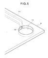
- Figs. 3 and 5 show structures of a gas introducing portion of a separator
- Figs. 4 and 6 show structures of the gas introducing portion of the separator and a fuel gas manifold in the fuel cell stack.
- the flat plate laminated type solid oxide fuel cell stack 1 is constructed by: laminating a plurality of unit cells 10 comprising a power generation cell 5 in which a fuel electrode layer 3 and an air electrode layer 4 are arranged on both surfaces of a solid electrolyte layer 2, a fuel electrode current collector 6 on the outer side of the fuel electrode layer 3, an air electrode current collector 7 on the outer side of the air electrode layer 4, and separators 8 on the outer side of each of the current collectors 6, 7 to form a stack structure; and applying load by means of bolting or the like in the laminating direction from both ends of the stack so that elements of the stack are pressure bonded and closely overlapped to each other.
- the solid electrolyte layer 2 is formed of stabilized zirconia (YSZ) doped with yttria, and the like.
- the fuel electrode layer 3 is formed of a metal such as Ni, Co, or a cermet such as Ni-YSZ, Co-YSZ.
- the air electrode layer 4 is formed of LaMnO 3 , LaCoO 3 and the like.
- the fuel electrode current collector 6 is formed of a sponge-like porous sintered metallic plate such as a Ni-based alloy, and the air electrode current collector 7 is formed of a sponge-like porous sintered metallic plate such as an Ag-based alloy.
- the separator 8 is formed of stainless steel and the like.
- the separator 8 is made of a stainless steel plate having a thickness of 2 mm to 3 mm.
- the separator 8 has a function of electrically connecting the power generation cells 5 to each other and of supplying reactant gas to the power generation cell 5.
- the separator 8 has a fuel gas passage 11 which introduces fuel gas from an outer peripheral part of the separator 8 and which discharges the fuel gas from a center portion 11a of a separator surface facing the fuel electrode current collector 6, and an oxidant gas passage 12 which introduces oxidant gas from an outer peripheral part of the separator 8 and which discharges the oxidant gas from a center portion 12a of a separator surface facing the air electrode current collector 7.
- a pair of gas openings 13, 14 extending through the separator 8 in the thickness direction is formed at both peripheral sides of the separator 8.
- one opening 13 is in communication with the fuel gas passage 11, and the other opening 14 is in communication with the oxidant gas passage 12. That is, fuel and oxidant gases can be supplied on each electrode surface of the power generation cell 5 from corresponding gas openings 13, 14 through the gas passages 11, 12.
- the gas openings of any two vertically-adjacent separators 8 are in communication with each other through ring-shaped insulating gaskets 15 and 16.
- a tubular fuel gas manifold 17 and a tubular oxidant gas manifold 18, which extend in the laminating direction in the stack, are formed by connecting (stacking) the respective gaskets 15, 16 in the laminating direction through the corresponding gas openings 13, 14 of each separator 8.
- Fuel gas and oxidant gas are introduced into these manifolds 17, 18 from the exterior portion, and then distributed and supplied to each electrode of each power generation cell 5 through throttle mechanisms 19, which will be describedbelow, and the gas passages 11, 12 from the gas openings 13, 14 of each separator 8.
- external pipes are connected to the side portion of the end plates 8a, 8b located at both ends of the stack so that fuel gas and oxidant gas (air) are supplied from both sides of the manifolds 17, 18, as shown in Fig. 1.
- through-holes 19 gas-flow throttle mechanisms are extended through the gas passage 11 in the thickness direction adjacent to each gas opening 13 having a substantially circular shape, as shown in Figs. 3 and 4.
- the through-hole 19 and the gas passage 11 are in communication with each other within the separator 8, so that the fuel gas manifold 17 and the gas passage 11 of the separator 8 are in communication with each other in the laminating direction (at the upper and lower ends of the through-hole 19).
- the diameter of the through-hole 19 is much smaller than that of the fuel gas manifold 17, and is set, for example, approximately 0.8 ⁇ when the diameter of the manifold 17 is set approximately 15 ⁇ , thereby pressure loss can be caused at the throttle mechanism.
- the diameter (0.8 ⁇ ) of the through-hole 19 is smaller than that of the fuel gas passage 11, for example, cross-section of which is a rectangular shape of approximately 3 mm ⁇ 1.5 mm. Accordingly, it is possible to prevent pressure loss at the connecting portion between the through-hole 19 and the fuel gas passage 11 from being produced, when the gas is supplied from the manifold. As shown by arrows in the Fig.
- the pressure loss at the gas-flow throttle mechanism is increased in order to reduce variations of the pressure loss at the downstream within each of the manifolds 17, 18, so that reduction (variation) of the gas volume flowing into the power generation cells 5 located downstream of the gas flow can be avoided, and reactant gas is distributed evenly to each of the power generation cells 5 in the laminating direction of the fuel cell stack. Accordingly, output of the fuel cell can be stabilized and the output efficiency can be improved. It is noted that, in this embodiment, the variations of the pressure loss in the downstream is significantly decreased from 15% to 5%, compared to the structure in which the gas-flow throttle mechanism is not provided between the gas passage and the gas opening of the separator.
- FIG. 5 Another embodiment of the gas-flow throttle mechanism can be adopted in which the fuel gas manifold 17 and the fuel gas passage 11 of the separator 8 are in communication with each other via the through-hole 19 in the lateral direction (that is, the direction intersecting with the manifold) as shown in Figs. 5 and 6.
- the diameter of the through-hole 19 is much smaller than that of the fuel gas manifold 17, pressure loss can be caused at the throttle mechanism.
- the diameter of the through-hole 19 is smaller than that of the fuel gas passage 11. Accordingly, as well as the embodiment described above, it is possible to prevent unnecessary pressure loss at the connecting portion between the through-hole 19 and the fuel gas passage 11 from being produced, when the gas is introduced from the manifold.
- the structure of the gas-flow throttle mechanism described above can be applied to the oxidant gas manifold 18 as well.
- the reactant gas is supplied from both ends of the manifold, variations of the pressure loss in the downstream of the manifold can be suppressed compared to a case where the reactant gas is supplied from one side of the manifold. Therefore, even distribution of the reactant gas can be realizedmore effectively.
- external reactant gases turn at the inlet portion, just after the gases flow into each manifold from both ends of the manifold in the lateral direction perpendicular to the manifold, and then flow within the manifold in the longitudinal direction (the laminating direction).
- the commutation effect obtained by changing the direction of the gas flow at the inlet portion also makes a substantial contribution to realizing more effective even distribution of the reactant gas through the manifolds.
- Such a reactant gas-supplying configuration may be more effective, as the number of the laminating layers is increased.
- the throttle mechanism 19 according to the present invention can be applied to both of the fuel gas manifold 17 and the oxidant gas manifold 18. However, it is important that the throttle mechanism 19 should be applied to at least fuel gas supply side (the fuel gas manifold), since uniform distribution of the fuel gas in the fuel gas supply side makes a great difference in the power generating performance and the efficiency of the fuel cell.
- gas volume distributed into each power generation cell through an internal manifold formed in a fuel cell stack can be equalized.
- output of the fuel cell can be stabilized and the output efficiency can be improved.
Landscapes
- Life Sciences & Earth Sciences (AREA)
- Engineering & Computer Science (AREA)
- Manufacturing & Machinery (AREA)
- Sustainable Development (AREA)
- Sustainable Energy (AREA)
- Chemical & Material Sciences (AREA)
- Chemical Kinetics & Catalysis (AREA)
- Electrochemistry (AREA)
- General Chemical & Material Sciences (AREA)
- Fuel Cell (AREA)
Applications Claiming Priority (3)
| Application Number | Priority Date | Filing Date | Title |
|---|---|---|---|
| JP2005045249 | 2005-02-22 | ||
| JP2006000695A JP2006269409A (ja) | 2005-02-22 | 2006-01-05 | 固体酸化物形燃料電池 |
| PCT/JP2006/302626 WO2006090621A1 (ja) | 2005-02-22 | 2006-02-15 | 固体酸化物形燃料電池 |
Publications (3)
| Publication Number | Publication Date |
|---|---|
| EP1852929A1 true EP1852929A1 (de) | 2007-11-07 |
| EP1852929A4 EP1852929A4 (de) | 2008-05-07 |
| EP1852929B1 EP1852929B1 (de) | 2010-10-27 |
Family
ID=36927262
Family Applications (1)
| Application Number | Title | Priority Date | Filing Date |
|---|---|---|---|
| EP06713767A Expired - Lifetime EP1852929B1 (de) | 2005-02-22 | 2006-02-15 | Festoxidbrennstoffzelle |
Country Status (5)
| Country | Link |
|---|---|
| US (1) | US8338047B2 (de) |
| EP (1) | EP1852929B1 (de) |
| JP (1) | JP2006269409A (de) |
| DE (1) | DE602006017809D1 (de) |
| WO (1) | WO2006090621A1 (de) |
Families Citing this family (4)
| Publication number | Priority date | Publication date | Assignee | Title |
|---|---|---|---|---|
| FR2902930B1 (fr) * | 2006-06-21 | 2009-11-27 | Commissariat Energie Atomique | Plaque bipolaire pour pile a combustible, et pile a combustible a distribution de fluide amelioree mettant en oeuvre de telles plaques |
| JP5502536B2 (ja) | 2010-03-17 | 2014-05-28 | 本田技研工業株式会社 | 燃料電池 |
| JP5819099B2 (ja) * | 2011-05-11 | 2015-11-18 | 日本特殊陶業株式会社 | 固体酸化物形燃料電池 |
| WO2014177212A1 (en) * | 2013-05-02 | 2014-11-06 | Haldor Topsøe A/S | Gas inlet for soec unit |
Family Cites Families (14)
| Publication number | Priority date | Publication date | Assignee | Title |
|---|---|---|---|---|
| JPS6096775A (ja) | 1983-10-31 | 1985-05-30 | Mitsui Mining & Smelting Co Ltd | 板条流電陽極 |
| JPS6096775U (ja) * | 1983-12-08 | 1985-07-02 | 株式会社富士電機総合研究所 | 積層型電池 |
| JPH0752652B2 (ja) * | 1986-04-07 | 1995-06-05 | 株式会社日立製作所 | 積層電池のマニホ−ルド構造 |
| DE68909720T2 (de) * | 1988-07-23 | 1994-02-03 | Fuji Electric Co Ltd | Brennstoffzelle mit einem festen Elektrolyten. |
| JP3113340B2 (ja) * | 1991-11-07 | 2000-11-27 | 三洋電機株式会社 | 内部マニホールド方式燃料電池 |
| JPH07201353A (ja) | 1993-11-29 | 1995-08-04 | Toshiba Corp | 燃料電池 |
| DE69804829T2 (de) * | 1997-07-16 | 2002-11-07 | Ballard Power Systems Inc., Burnaby | Elastische dichtung für eine membranelektrodenanordnung in einer elektrochemischen brennstoffzelle und herstellungsverfahren dafür |
| US6174616B1 (en) * | 1998-10-07 | 2001-01-16 | Plug Power Inc. | Fuel cell assembly unit for promoting fluid service and design flexibility |
| US7226688B2 (en) * | 1999-09-10 | 2007-06-05 | Honda Motor Co., Ltd. | Fuel cell |
| JP2001155759A (ja) | 1999-11-30 | 2001-06-08 | Matsushita Electric Ind Co Ltd | 高分子電解質型燃料電池 |
| US7122266B2 (en) | 2001-09-13 | 2006-10-17 | Ngk Insulators, Ltd. | Holding member for holding an electrochemical cell, a holding substrate for the same, an electrochemical system and a connecting member for electrochemical cells |
| JP3787118B2 (ja) | 2002-11-22 | 2006-06-21 | 株式会社東芝 | 燃料電池 |
| AU2004216063B2 (en) | 2003-02-27 | 2009-02-19 | Protonex Technology Corporation | Externally manifolded membrane based electrochemical cell stacks |
| JP3878619B2 (ja) | 2004-03-31 | 2007-02-07 | 株式会社東芝 | 液体燃料電池 |
-
2006
- 2006-01-05 JP JP2006000695A patent/JP2006269409A/ja active Pending
- 2006-02-15 EP EP06713767A patent/EP1852929B1/de not_active Expired - Lifetime
- 2006-02-15 US US11/884,759 patent/US8338047B2/en not_active Expired - Fee Related
- 2006-02-15 DE DE602006017809T patent/DE602006017809D1/de not_active Expired - Lifetime
- 2006-02-15 WO PCT/JP2006/302626 patent/WO2006090621A1/ja not_active Ceased
Also Published As
| Publication number | Publication date |
|---|---|
| JP2006269409A (ja) | 2006-10-05 |
| US20090042081A1 (en) | 2009-02-12 |
| WO2006090621A1 (ja) | 2006-08-31 |
| US8338047B2 (en) | 2012-12-25 |
| EP1852929B1 (de) | 2010-10-27 |
| DE602006017809D1 (de) | 2010-12-09 |
| EP1852929A4 (de) | 2008-05-07 |
Similar Documents
| Publication | Publication Date | Title |
|---|---|---|
| US7329471B2 (en) | Methods and apparatus for assembling solid oxide fuel cells | |
| CN102906920B (zh) | 固体氧化物燃料电池 | |
| EP1695408B1 (de) | Brennstoffzelle und brennstoffzellenstapel | |
| US20060003220A1 (en) | Fuel cell | |
| EP1673831B1 (de) | Integrierter brennstoffzellenstapel und katalytische verbrennungsvorrichtung, baugruppe und benutzungsverfahren | |
| EP2787570B1 (de) | Verfahren zur herstellung einer brennstoffzellenstapelvorrichtung | |
| US7794891B2 (en) | Fuel cell with interweaving current collector and membrane electrode assembly | |
| JP4300947B2 (ja) | 固体酸化物形燃料電池 | |
| JP4461949B2 (ja) | 固体酸化物形燃料電池 | |
| JP2006066387A (ja) | 燃料電池 | |
| JP2005203255A (ja) | 燃料電池のマニホールド構造 | |
| US20080274388A1 (en) | Solid Oxide Type Fuel Cell | |
| EP1852929B1 (de) | Festoxidbrennstoffzelle | |
| JP5239174B2 (ja) | 燃料電池 | |
| US20040038103A1 (en) | Solid polymer electrolyte fuel cell assembly | |
| JP2009245627A (ja) | 固体酸化物形燃料電池 | |
| JP4984374B2 (ja) | 燃料電池 | |
| JP2008226704A (ja) | 固体酸化物形燃料電池および酸化剤ガスの供給方法 | |
| JP4963195B2 (ja) | セパレータおよび平板型固体酸化物形燃料電池 | |
| JP6797153B2 (ja) | 電気化学反応セルスタック | |
| JP2006086018A (ja) | 固体酸化物形燃料電池 | |
| JP4899387B2 (ja) | 固体酸化物形燃料電池 | |
| JP4706191B2 (ja) | 固体酸化物形燃料電池 | |
| JP5211706B2 (ja) | 固体酸化物形燃料電池 | |
| EP4571902A1 (de) | Strömungsplatte einer brennstoffzelle |
Legal Events
| Date | Code | Title | Description |
|---|---|---|---|
| PUAI | Public reference made under article 153(3) epc to a published international application that has entered the european phase |
Free format text: ORIGINAL CODE: 0009012 |
|
| 17P | Request for examination filed |
Effective date: 20070912 |
|
| AK | Designated contracting states |
Kind code of ref document: A1 Designated state(s): AT BE BG CH CY CZ DE DK EE ES FI FR GB GR HU IE IS IT LI LT LU LV MC NL PL PT RO SE SI SK TR |
|
| A4 | Supplementary search report drawn up and despatched |
Effective date: 20080403 |
|
| DAX | Request for extension of the european patent (deleted) | ||
| 17Q | First examination report despatched |
Effective date: 20080718 |
|
| GRAP | Despatch of communication of intention to grant a patent |
Free format text: ORIGINAL CODE: EPIDOSNIGR1 |
|
| RIN1 | Information on inventor provided before grant (corrected) |
Inventor name: MURAKAMI, NAOYA,CENTRAL RES. INST. NAKA RES. CTR. Inventor name: KOTANI, TAKAFUMI,CENTRAL RES. INST. NAKA RES.CTR. |
|
| GRAS | Grant fee paid |
Free format text: ORIGINAL CODE: EPIDOSNIGR3 |
|
| GRAA | (expected) grant |
Free format text: ORIGINAL CODE: 0009210 |
|
| AK | Designated contracting states |
Kind code of ref document: B1 Designated state(s): AT BE BG CH CY CZ DE DK EE ES FI FR GB GR HU IE IS IT LI LT LU LV MC NL PL PT RO SE SI SK TR |
|
| REG | Reference to a national code |
Ref country code: GB Ref legal event code: FG4D |
|
| REG | Reference to a national code |
Ref country code: CH Ref legal event code: EP |
|
| REG | Reference to a national code |
Ref country code: IE Ref legal event code: FG4D |
|
| REF | Corresponds to: |
Ref document number: 602006017809 Country of ref document: DE Date of ref document: 20101209 Kind code of ref document: P |
|
| REG | Reference to a national code |
Ref country code: NL Ref legal event code: VDEP Effective date: 20101027 |
|
| LTIE | Lt: invalidation of european patent or patent extension |
Effective date: 20101027 |
|
| PG25 | Lapsed in a contracting state [announced via postgrant information from national office to epo] |
Ref country code: LT Free format text: LAPSE BECAUSE OF FAILURE TO SUBMIT A TRANSLATION OF THE DESCRIPTION OR TO PAY THE FEE WITHIN THE PRESCRIBED TIME-LIMIT Effective date: 20101027 |
|
| PG25 | Lapsed in a contracting state [announced via postgrant information from national office to epo] |
Ref country code: PT Free format text: LAPSE BECAUSE OF FAILURE TO SUBMIT A TRANSLATION OF THE DESCRIPTION OR TO PAY THE FEE WITHIN THE PRESCRIBED TIME-LIMIT Effective date: 20110228 Ref country code: BG Free format text: LAPSE BECAUSE OF FAILURE TO SUBMIT A TRANSLATION OF THE DESCRIPTION OR TO PAY THE FEE WITHIN THE PRESCRIBED TIME-LIMIT Effective date: 20110127 Ref country code: FI Free format text: LAPSE BECAUSE OF FAILURE TO SUBMIT A TRANSLATION OF THE DESCRIPTION OR TO PAY THE FEE WITHIN THE PRESCRIBED TIME-LIMIT Effective date: 20101027 Ref country code: LV Free format text: LAPSE BECAUSE OF FAILURE TO SUBMIT A TRANSLATION OF THE DESCRIPTION OR TO PAY THE FEE WITHIN THE PRESCRIBED TIME-LIMIT Effective date: 20101027 Ref country code: SI Free format text: LAPSE BECAUSE OF FAILURE TO SUBMIT A TRANSLATION OF THE DESCRIPTION OR TO PAY THE FEE WITHIN THE PRESCRIBED TIME-LIMIT Effective date: 20101027 Ref country code: NL Free format text: LAPSE BECAUSE OF FAILURE TO SUBMIT A TRANSLATION OF THE DESCRIPTION OR TO PAY THE FEE WITHIN THE PRESCRIBED TIME-LIMIT Effective date: 20101027 Ref country code: AT Free format text: LAPSE BECAUSE OF FAILURE TO SUBMIT A TRANSLATION OF THE DESCRIPTION OR TO PAY THE FEE WITHIN THE PRESCRIBED TIME-LIMIT Effective date: 20101027 Ref country code: IS Free format text: LAPSE BECAUSE OF FAILURE TO SUBMIT A TRANSLATION OF THE DESCRIPTION OR TO PAY THE FEE WITHIN THE PRESCRIBED TIME-LIMIT Effective date: 20110227 Ref country code: SE Free format text: LAPSE BECAUSE OF FAILURE TO SUBMIT A TRANSLATION OF THE DESCRIPTION OR TO PAY THE FEE WITHIN THE PRESCRIBED TIME-LIMIT Effective date: 20101027 |
|
| PG25 | Lapsed in a contracting state [announced via postgrant information from national office to epo] |
Ref country code: GR Free format text: LAPSE BECAUSE OF FAILURE TO SUBMIT A TRANSLATION OF THE DESCRIPTION OR TO PAY THE FEE WITHIN THE PRESCRIBED TIME-LIMIT Effective date: 20110128 Ref country code: BE Free format text: LAPSE BECAUSE OF FAILURE TO SUBMIT A TRANSLATION OF THE DESCRIPTION OR TO PAY THE FEE WITHIN THE PRESCRIBED TIME-LIMIT Effective date: 20101027 |
|
| PG25 | Lapsed in a contracting state [announced via postgrant information from national office to epo] |
Ref country code: CZ Free format text: LAPSE BECAUSE OF FAILURE TO SUBMIT A TRANSLATION OF THE DESCRIPTION OR TO PAY THE FEE WITHIN THE PRESCRIBED TIME-LIMIT Effective date: 20101027 Ref country code: EE Free format text: LAPSE BECAUSE OF FAILURE TO SUBMIT A TRANSLATION OF THE DESCRIPTION OR TO PAY THE FEE WITHIN THE PRESCRIBED TIME-LIMIT Effective date: 20101027 Ref country code: ES Free format text: LAPSE BECAUSE OF FAILURE TO SUBMIT A TRANSLATION OF THE DESCRIPTION OR TO PAY THE FEE WITHIN THE PRESCRIBED TIME-LIMIT Effective date: 20110207 |
|
| PG25 | Lapsed in a contracting state [announced via postgrant information from national office to epo] |
Ref country code: DK Free format text: LAPSE BECAUSE OF FAILURE TO SUBMIT A TRANSLATION OF THE DESCRIPTION OR TO PAY THE FEE WITHIN THE PRESCRIBED TIME-LIMIT Effective date: 20101027 Ref country code: RO Free format text: LAPSE BECAUSE OF FAILURE TO SUBMIT A TRANSLATION OF THE DESCRIPTION OR TO PAY THE FEE WITHIN THE PRESCRIBED TIME-LIMIT Effective date: 20101027 Ref country code: PL Free format text: LAPSE BECAUSE OF FAILURE TO SUBMIT A TRANSLATION OF THE DESCRIPTION OR TO PAY THE FEE WITHIN THE PRESCRIBED TIME-LIMIT Effective date: 20101027 Ref country code: SK Free format text: LAPSE BECAUSE OF FAILURE TO SUBMIT A TRANSLATION OF THE DESCRIPTION OR TO PAY THE FEE WITHIN THE PRESCRIBED TIME-LIMIT Effective date: 20101027 |
|
| PLBE | No opposition filed within time limit |
Free format text: ORIGINAL CODE: 0009261 |
|
| STAA | Information on the status of an ep patent application or granted ep patent |
Free format text: STATUS: NO OPPOSITION FILED WITHIN TIME LIMIT |
|
| PG25 | Lapsed in a contracting state [announced via postgrant information from national office to epo] |
Ref country code: MC Free format text: LAPSE BECAUSE OF NON-PAYMENT OF DUE FEES Effective date: 20110228 |
|
| REG | Reference to a national code |
Ref country code: CH Ref legal event code: PL |
|
| 26N | No opposition filed |
Effective date: 20110728 |
|
| PG25 | Lapsed in a contracting state [announced via postgrant information from national office to epo] |
Ref country code: LI Free format text: LAPSE BECAUSE OF NON-PAYMENT OF DUE FEES Effective date: 20110228 Ref country code: CH Free format text: LAPSE BECAUSE OF NON-PAYMENT OF DUE FEES Effective date: 20110228 |
|
| REG | Reference to a national code |
Ref country code: IE Ref legal event code: MM4A |
|
| REG | Reference to a national code |
Ref country code: DE Ref legal event code: R097 Ref document number: 602006017809 Country of ref document: DE Effective date: 20110728 |
|
| PG25 | Lapsed in a contracting state [announced via postgrant information from national office to epo] |
Ref country code: IT Free format text: LAPSE BECAUSE OF FAILURE TO SUBMIT A TRANSLATION OF THE DESCRIPTION OR TO PAY THE FEE WITHIN THE PRESCRIBED TIME-LIMIT Effective date: 20101027 |
|
| PG25 | Lapsed in a contracting state [announced via postgrant information from national office to epo] |
Ref country code: IE Free format text: LAPSE BECAUSE OF NON-PAYMENT OF DUE FEES Effective date: 20110215 |
|
| PG25 | Lapsed in a contracting state [announced via postgrant information from national office to epo] |
Ref country code: CY Free format text: LAPSE BECAUSE OF FAILURE TO SUBMIT A TRANSLATION OF THE DESCRIPTION OR TO PAY THE FEE WITHIN THE PRESCRIBED TIME-LIMIT Effective date: 20101027 Ref country code: LU Free format text: LAPSE BECAUSE OF NON-PAYMENT OF DUE FEES Effective date: 20110215 |
|
| PG25 | Lapsed in a contracting state [announced via postgrant information from national office to epo] |
Ref country code: TR Free format text: LAPSE BECAUSE OF FAILURE TO SUBMIT A TRANSLATION OF THE DESCRIPTION OR TO PAY THE FEE WITHIN THE PRESCRIBED TIME-LIMIT Effective date: 20101027 |
|
| PG25 | Lapsed in a contracting state [announced via postgrant information from national office to epo] |
Ref country code: HU Free format text: LAPSE BECAUSE OF FAILURE TO SUBMIT A TRANSLATION OF THE DESCRIPTION OR TO PAY THE FEE WITHIN THE PRESCRIBED TIME-LIMIT Effective date: 20101027 |
|
| REG | Reference to a national code |
Ref country code: FR Ref legal event code: PLFP Year of fee payment: 10 |
|
| PGFP | Annual fee paid to national office [announced via postgrant information from national office to epo] |
Ref country code: DE Payment date: 20150210 Year of fee payment: 10 |
|
| REG | Reference to a national code |
Ref country code: DE Ref legal event code: R082 Ref document number: 602006017809 Country of ref document: DE Representative=s name: PATENTANWAELTE WEICKMANN & WEICKMANN, DE Ref country code: DE Ref legal event code: R082 Ref document number: 602006017809 Country of ref document: DE Representative=s name: WEICKMANN & WEICKMANN PATENTANWAELTE - RECHTSA, DE |
|
| PGFP | Annual fee paid to national office [announced via postgrant information from national office to epo] |
Ref country code: FR Payment date: 20150210 Year of fee payment: 10 Ref country code: GB Payment date: 20150211 Year of fee payment: 10 |
|
| REG | Reference to a national code |
Ref country code: DE Ref legal event code: R119 Ref document number: 602006017809 Country of ref document: DE |
|
| GBPC | Gb: european patent ceased through non-payment of renewal fee |
Effective date: 20160215 |
|
| REG | Reference to a national code |
Ref country code: FR Ref legal event code: ST Effective date: 20161028 |
|
| PG25 | Lapsed in a contracting state [announced via postgrant information from national office to epo] |
Ref country code: DE Free format text: LAPSE BECAUSE OF NON-PAYMENT OF DUE FEES Effective date: 20160901 Ref country code: FR Free format text: LAPSE BECAUSE OF NON-PAYMENT OF DUE FEES Effective date: 20160229 Ref country code: GB Free format text: LAPSE BECAUSE OF NON-PAYMENT OF DUE FEES Effective date: 20160215 |