EP1852941A1 - Verbinder für Lüsterklemme - Google Patents
Verbinder für Lüsterklemme Download PDFInfo
- Publication number
- EP1852941A1 EP1852941A1 EP06009052A EP06009052A EP1852941A1 EP 1852941 A1 EP1852941 A1 EP 1852941A1 EP 06009052 A EP06009052 A EP 06009052A EP 06009052 A EP06009052 A EP 06009052A EP 1852941 A1 EP1852941 A1 EP 1852941A1
- Authority
- EP
- European Patent Office
- Prior art keywords
- wires
- connector
- cylindrical body
- adjoining
- conduction plate
- Prior art date
- Legal status (The legal status is an assumption and is not a legal conclusion. Google has not performed a legal analysis and makes no representation as to the accuracy of the status listed.)
- Withdrawn
Links
- 239000011796 hollow space material Substances 0.000 claims abstract description 8
- 238000003780 insertion Methods 0.000 claims abstract description 7
- 230000037431 insertion Effects 0.000 claims abstract description 7
- 230000013011 mating Effects 0.000 claims abstract description 6
- 229910001369 Brass Inorganic materials 0.000 claims description 8
- 239000010951 brass Substances 0.000 claims description 8
- 229910000831 Steel Inorganic materials 0.000 claims description 6
- 239000010959 steel Substances 0.000 claims description 6
- 238000009434 installation Methods 0.000 claims description 2
- 239000000463 material Substances 0.000 description 4
- 238000003754 machining Methods 0.000 description 3
- 238000004080 punching Methods 0.000 description 3
- RYGMFSIKBFXOCR-UHFFFAOYSA-N Copper Chemical compound [Cu] RYGMFSIKBFXOCR-UHFFFAOYSA-N 0.000 description 2
- 239000000956 alloy Substances 0.000 description 2
- 229910052802 copper Inorganic materials 0.000 description 2
- 239000010949 copper Substances 0.000 description 2
- 239000002184 metal Substances 0.000 description 2
- 229910052751 metal Inorganic materials 0.000 description 2
- 238000003466 welding Methods 0.000 description 2
- 229910045601 alloy Inorganic materials 0.000 description 1
- 238000005452 bending Methods 0.000 description 1
- 239000004020 conductor Substances 0.000 description 1
- 238000010276 construction Methods 0.000 description 1
- 238000010292 electrical insulation Methods 0.000 description 1
- 238000004519 manufacturing process Methods 0.000 description 1
- 239000007769 metal material Substances 0.000 description 1
- 238000000034 method Methods 0.000 description 1
- 238000012986 modification Methods 0.000 description 1
- 230000004048 modification Effects 0.000 description 1
- 238000005096 rolling process Methods 0.000 description 1
Images


Classifications
-
- H—ELECTRICITY
- H01—ELECTRIC ELEMENTS
- H01R—ELECTRICALLY-CONDUCTIVE CONNECTIONS; STRUCTURAL ASSOCIATIONS OF A PLURALITY OF MUTUALLY-INSULATED ELECTRICAL CONNECTING ELEMENTS; COUPLING DEVICES; CURRENT COLLECTORS
- H01R4/00—Electrically-conductive connections between two or more conductive members in direct contact, i.e. touching one another; Means for effecting or maintaining such contact; Electrically-conductive connections having two or more spaced connecting locations for conductors and using contact members penetrating insulation
- H01R4/28—Clamped connections, spring connections
- H01R4/30—Clamped connections, spring connections utilising a screw or nut clamping member
- H01R4/36—Conductive members located under tip of screw
- H01R4/363—Conductive members located under tip of screw with intermediate part between tip and conductive member
-
- H—ELECTRICITY
- H01—ELECTRIC ELEMENTS
- H01R—ELECTRICALLY-CONDUCTIVE CONNECTIONS; STRUCTURAL ASSOCIATIONS OF A PLURALITY OF MUTUALLY-INSULATED ELECTRICAL CONNECTING ELEMENTS; COUPLING DEVICES; CURRENT COLLECTORS
- H01R9/00—Structural associations of a plurality of mutually-insulated electrical connecting elements, e.g. terminal strips or terminal blocks; Terminals or binding posts mounted upon a base or in a case; Bases therefor
- H01R9/22—Bases, e.g. strip, block, panel
- H01R9/24—Terminal blocks
Definitions
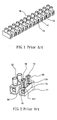
- FIG. 2 shows a conventional connector for the terminal block of FIG. 1.
- the drawing depicts the housing of a connector 13 inside its elongated pole 11 (shown in phantom lines) of the mass block.
- Two wires to be electrically connected for either power or signal relay purposes can be inserted each into the two opposite openings of a connector 13.
- a screw 15 is provided near each end of the connector 13 that can be screwed into its corresponding screw hole 131, which is opened through the entire thickness of the wall of the connector's generally cylindrical body and allows the passing through of its corresponding screw 15.
- the screw 15 sinks into a screw well 16 provided on the pole 11 of the mass block.
- An electrically conductive resilient cover plate 14 is provided ahead of the opening of the screw hole 131 along the screw-in direction of each of the screws 15.
- the screw 15 can be driven inward so as to push the cover plate 14 onto the wire end.
- the screw-in of the screw 15 allows the wire end to be squeezed between the plate 14 and the cylindrical housing wall of the connector 13 opposite the screw hole 131. With sufficient screwing force, the connector 13 allows to both prevent the break off of the wire and ensure good electrical contact between the wire and the electrically conductive housing of the connector 13.
- the present invention achieves the above by providing a connector for a terminal block for adjoining a pair of wires for providing electrical conduction between said wires, said connector comprising a cylindrical body having one screw hole near each end of said body and a wire end plate formed internally to and at substantially the longitudinal center of said body for limiting insertion of said wires; and a conduction plate inserted into the hollow space of said cylindrical body, said conduction plate having a length substantially the same as that of said cylindrical body along the longitudinal direction thereof; wherein said conduction plate having a concaved surface conforming to the generally spherical cross section of said wires for partially enclosing said wires when inserted for said adjoining; said concaved surface providing low electrical resistance between said adjoining wires when two screws mating with said screw holes are installed and each driven firmly onto the corresponding one of said adjoining wires thereby squeezing said wires firmly onto said conduction plate.
- the depicted preferred embodiment of the wire adjoining connector 23 of the present invention as illustrated herein has an end shape that resembles the capital English letter "D."
- the two screw holes 231 for the wire-securing screws are formed on the flat portion of the cylindrical body of the connector 23, as is see in FIG. 5.
- the flat portion of the cylindrical body of the connector 23 is where the two ends of the roll-formed sheet material meet.
- the generally cylindrical-shaped configuration of the connector 23 of FIG. 5 encloses a hollow internal space, in which a conduction plate 25 can be inserted.
- the conduction plate 25 is preferably made of a commercially optimized electrical conduction material, brass with sufficient copper content for example.
- the conduction plate 25 has an end shape in conformity with the curved segment of the letter "D" end shape of the connector 23 opposite to the straight vertical segment thereof as it is inserted into the hollow space of the connector 23 directly next to that curved wall.
- the conduction plate 25 should be fixed to its correspondingly shaped inner sidewall of the connector 23 via, for example, spot welding that allows best possible electrical conduction between the two.
- the conduction plate 25 has a length along the longitudinal direction of the connector 23 that is substantially equal to the length of the connector in which it is inserted.
- FIG. 5 There is one single punching through the connector body sidewall is shown in FIG. 5, however, two punchings each with smaller bent wall than in the case of one single bent plate are also applicable.
- the two smaller bent plates formed substantially at the middle along the longitudinal length of the connector body can be aligned opposite to each other to make up an equivalent single wire end stopping plate 232.
- the screw-in of the wire-securing screw 24 allows the wire end to be tightly squeezed between the screw tip (or the resilient cover plate should one be used) and the concaved inner surface of the conduction plate 25.
- the wire adjoining connector 23 of the present invention allows to both prevent the break off of the wires and ensure good electrical contact between the two adjoined wires.
- the electrical conduction between any pair of adjoined wires is significantly better than that is provided by conventional terminal blocks. This improved electrical conduction is due to the presence of the contoured conduction plate in the connector body.
- the inwardly curved surface of the conduction plate conforms to and perfectly partially encloses the generally spherical cross section of any wire to be adjoined.
- the connector for the terminal block in accordance with the teaching of the present invention can also enjoy the benefit of cost reduction.
- the connector body can be made of structurally strong and yet cheap metallic or alloy material.
- plated steel sheets which are much cheaper than brass, can be used to make the connector body.
- Steel sheet provides good structural strength for the connector while is also electrically conductive. Therefore, a wire adjoining connector in accordance with the teaching of the present invention having a steel body and an inner lining brass conduction plate is capable of achieving optimized price-performance characteristics.
Landscapes
- Connections Arranged To Contact A Plurality Of Conductors (AREA)
Priority Applications (1)
| Application Number | Priority Date | Filing Date | Title |
|---|---|---|---|
| EP06009052A EP1852941A1 (de) | 2006-05-02 | 2006-05-02 | Verbinder für Lüsterklemme |
Applications Claiming Priority (1)
| Application Number | Priority Date | Filing Date | Title |
|---|---|---|---|
| EP06009052A EP1852941A1 (de) | 2006-05-02 | 2006-05-02 | Verbinder für Lüsterklemme |
Publications (1)
| Publication Number | Publication Date |
|---|---|
| EP1852941A1 true EP1852941A1 (de) | 2007-11-07 |
Family
ID=37067545
Family Applications (1)
| Application Number | Title | Priority Date | Filing Date |
|---|---|---|---|
| EP06009052A Withdrawn EP1852941A1 (de) | 2006-05-02 | 2006-05-02 | Verbinder für Lüsterklemme |
Country Status (1)
| Country | Link |
|---|---|
| EP (1) | EP1852941A1 (de) |
Cited By (9)
| Publication number | Priority date | Publication date | Assignee | Title |
|---|---|---|---|---|
| EP2075876A1 (de) | 2007-12-29 | 2009-07-01 | Gaosong Ding | Stecker für Klemmenblock |
| GB2506143A (en) * | 2012-09-21 | 2014-03-26 | Brencham 1988 Ltd | Electrical terminal having concave element |
| CN105826708A (zh) * | 2016-05-23 | 2016-08-03 | 苏州丰年科技股份有限公司 | 一种多芯插入式连接器的连接结构 |
| CN110492255A (zh) * | 2019-07-19 | 2019-11-22 | 中航光电科技股份有限公司 | 一种接触件 |
| US10591114B1 (en) * | 2019-09-19 | 2020-03-17 | Elemental LED, Inc. | Connectors for linear lighting |
| DE102018127972A1 (de) * | 2018-09-14 | 2020-03-19 | Tdk Electronics Ag | Kondensatoranschlussadapter und Anordnung, die den Kondensatoranschlussadapter umfasst |
| US10826202B1 (en) | 2020-06-24 | 2020-11-03 | Elemental LED, Inc. | Connectors for linear lighting |
| DE202020100565U1 (de) * | 2020-02-03 | 2021-05-06 | WAGO Verwaltungsgesellschaft mit beschränkter Haftung | Anschlussklemme |
| WO2021101454A1 (en) * | 2019-11-18 | 2021-05-27 | Brs Raziskave In Sistemi D.O.O. | Housing for a filter device with a connection box for connecting to an electrical grid |
Citations (2)
| Publication number | Priority date | Publication date | Assignee | Title |
|---|---|---|---|---|
| DE3245136A1 (de) * | 1982-12-07 | 1984-06-07 | Gustav 7407 Rottenburg Flier | Klemmvorrichtung zum verbinden von draehten und dergl. |
| EP0406510A1 (de) * | 1989-07-06 | 1991-01-09 | ELETTRO GIBI S.p.A. | Haltebuchse für elektrische Klemmen |
-
2006
- 2006-05-02 EP EP06009052A patent/EP1852941A1/de not_active Withdrawn
Patent Citations (2)
| Publication number | Priority date | Publication date | Assignee | Title |
|---|---|---|---|---|
| DE3245136A1 (de) * | 1982-12-07 | 1984-06-07 | Gustav 7407 Rottenburg Flier | Klemmvorrichtung zum verbinden von draehten und dergl. |
| EP0406510A1 (de) * | 1989-07-06 | 1991-01-09 | ELETTRO GIBI S.p.A. | Haltebuchse für elektrische Klemmen |
Cited By (12)
| Publication number | Priority date | Publication date | Assignee | Title |
|---|---|---|---|---|
| EP2075876A1 (de) | 2007-12-29 | 2009-07-01 | Gaosong Ding | Stecker für Klemmenblock |
| EP2075875A1 (de) | 2007-12-29 | 2009-07-01 | Gaosong Ding | Stecker für Klemmenblock |
| GB2506143A (en) * | 2012-09-21 | 2014-03-26 | Brencham 1988 Ltd | Electrical terminal having concave element |
| GB2506143B (en) * | 2012-09-21 | 2016-04-06 | Brencham 1988 Ltd | Electrical terminal |
| CN105826708A (zh) * | 2016-05-23 | 2016-08-03 | 苏州丰年科技股份有限公司 | 一种多芯插入式连接器的连接结构 |
| DE102018127972A1 (de) * | 2018-09-14 | 2020-03-19 | Tdk Electronics Ag | Kondensatoranschlussadapter und Anordnung, die den Kondensatoranschlussadapter umfasst |
| DE102018127972B4 (de) | 2018-09-14 | 2021-08-05 | Tdk Electronics Ag | Kondensatoranschlussadapter und Anordnung, die den Kondensatoranschlussadapter umfasst |
| CN110492255A (zh) * | 2019-07-19 | 2019-11-22 | 中航光电科技股份有限公司 | 一种接触件 |
| US10591114B1 (en) * | 2019-09-19 | 2020-03-17 | Elemental LED, Inc. | Connectors for linear lighting |
| WO2021101454A1 (en) * | 2019-11-18 | 2021-05-27 | Brs Raziskave In Sistemi D.O.O. | Housing for a filter device with a connection box for connecting to an electrical grid |
| DE202020100565U1 (de) * | 2020-02-03 | 2021-05-06 | WAGO Verwaltungsgesellschaft mit beschränkter Haftung | Anschlussklemme |
| US10826202B1 (en) | 2020-06-24 | 2020-11-03 | Elemental LED, Inc. | Connectors for linear lighting |
Similar Documents
| Publication | Publication Date | Title |
|---|---|---|
| CN101325288B (zh) | 具有改进的母线的压入式接线器 | |
| CN1096129C (zh) | 具有带改进的固定装置的端子的电连接器 | |
| JP7080876B2 (ja) | 導体接続端子 | |
| US8251758B2 (en) | Electrical contact | |
| EP2483969B1 (de) | Einteilige leitfähige klemme für einen einführungsdraht-stecker | |
| CN100592574C (zh) | 内孔端子 | |
| JP4898296B2 (ja) | 接続部材 | |
| US20070123084A1 (en) | Electric contact and female terminal | |
| EP2075875A1 (de) | Stecker für Klemmenblock | |
| KR20070104220A (ko) | 전기 연결 클램프 | |
| US7677919B1 (en) | Battery connector | |
| JPWO2009101965A1 (ja) | 端子金具及びワイヤーハーネス | |
| US9083091B1 (en) | Electrical terminal connector for solderless connection of parts to electrical contact holes | |
| US7485016B2 (en) | Female terminal with guiding piece | |
| EP1852941A1 (de) | Verbinder für Lüsterklemme | |
| US20250079726A1 (en) | Piercing Type Motor Terminal Connector | |
| CN101546881A (zh) | 连接器 | |
| EP2458694B1 (de) | Anschlussanordnung und Verfahren zum Verbinden einer Leiters an ein Anschlusselement | |
| US20030220025A1 (en) | Terminal material strip assembly | |
| EP3989363A1 (de) | Elektrischer crimpanschluss | |
| US6604958B2 (en) | Terminal and electrical connector with the terminal | |
| CN115023861A (zh) | 具有多个端子的布线室 | |
| CN218770176U (zh) | 一种电连接器端子 | |
| CN201966370U (zh) | 端子结构及使用此端子结构的电连接器 | |
| JP2009021148A (ja) | 電線接続構造 |
Legal Events
| Date | Code | Title | Description |
|---|---|---|---|
| PUAI | Public reference made under article 153(3) epc to a published international application that has entered the european phase |
Free format text: ORIGINAL CODE: 0009012 |
|
| AK | Designated contracting states |
Kind code of ref document: A1 Designated state(s): AT BE BG CH CY CZ DE DK EE ES FI FR GB GR HU IE IS IT LI LT LU LV MC NL PL PT RO SE SI SK TR |
|
| AX | Request for extension of the european patent |
Extension state: AL BA HR MK YU |
|
| AKX | Designation fees paid | ||
| STAA | Information on the status of an ep patent application or granted ep patent |
Free format text: STATUS: THE APPLICATION IS DEEMED TO BE WITHDRAWN |
|
| 18D | Application deemed to be withdrawn |
Effective date: 20080508 |
|
| REG | Reference to a national code |
Ref country code: DE Ref legal event code: 8566 |