EP1852990B1 - Dispositif et procédé pour la synchronisation horaire dans un système de commande distribuée - Google Patents
Dispositif et procédé pour la synchronisation horaire dans un système de commande distribuée Download PDFInfo
- Publication number
- EP1852990B1 EP1852990B1 EP07105955.4A EP07105955A EP1852990B1 EP 1852990 B1 EP1852990 B1 EP 1852990B1 EP 07105955 A EP07105955 A EP 07105955A EP 1852990 B1 EP1852990 B1 EP 1852990B1
- Authority
- EP
- European Patent Office
- Prior art keywords
- frequency
- compensation
- time
- interval
- time offset
- Prior art date
- Legal status (The legal status is an assumption and is not a legal conclusion. Google has not performed a legal analysis and makes no representation as to the accuracy of the status listed.)
- Ceased
Links
Images



Classifications
-
- H—ELECTRICITY
- H04—ELECTRIC COMMUNICATION TECHNIQUE
- H04J—MULTIPLEX COMMUNICATION
- H04J3/00—Time-division multiplex systems
- H04J3/02—Details
- H04J3/06—Synchronising arrangements
- H04J3/0635—Clock or time synchronisation in a network
- H04J3/0638—Clock or time synchronisation among nodes; Internode synchronisation
- H04J3/0658—Clock or time synchronisation among packet nodes
- H04J3/0661—Clock or time synchronisation among packet nodes using timestamps
- H04J3/0664—Clock or time synchronisation among packet nodes using timestamps unidirectional timestamps
-
- H—ELECTRICITY
- H04—ELECTRIC COMMUNICATION TECHNIQUE
- H04L—TRANSMISSION OF DIGITAL INFORMATION, e.g. TELEGRAPHIC COMMUNICATION
- H04L7/00—Arrangements for synchronising receiver with transmitter
- H04L7/02—Speed or phase control by the received code signals, the signals containing no special synchronisation information
Definitions
- the present invention relates to a device and a method for providing time synchronization in a distributed control system.
- a distributed control system includes a set of nodes interconnected through one or multiple network communication links.
- the network communication links may include a packetized link, such as an Ethernet, or one or more of various packetized links, which can be employed in a distributed control system application.
- packetized link such as an Ethernet
- packetized links which can be employed in a distributed control system application.
- time synchronization In a distributed control system including a plurality of clocks, time synchronization must be employed in order to reduce instabilities inherent in source oscillators and time drift effect in use environment conditions (refers to reference 1 below).
- a residential bridge referred as a residential Ethernet, is considering time synchronization in order to provide traffic streaming, sampling of data streams in source and destination devices, and synchronized clocks for indication of such streams (refers to reference 2 below).
- the distributed control system In order to perform a precise time synchronization, the distributed control system must have synchronization performance in which a slave clock can be locked to a master clock in both clock time and a clock frequency.
- an IEEE 1588 standard prescribes time formats and defines a plurality of messages that can be used to distribute timing information, but does not define a scheme for achieving time synchronization.
- Reference [1] discloses a frequency compensation clock that can perform precise frequency and time synchronizations using an IEEE 1588 protocol, in order to change timing information.
- FIG. 1 is a ladder diagram illustrating a basic operation procedure for time synchronization in a general distributed control system, which discloses a basic operation between a master clock and a slave clock in a distributed control system according to the IEEE 1588 protocol.
- the master clock periodically transmits a synchronization message (sync) including its own lunching time to the slave clock, thereby performing an operation for time synchronization at regular intervals.
- the master clock can transmit opening time through an optional message (follow-up) in a similar manner.
- a delay request (not shown) is transmitted from the slave clock to the master clock in order to confirm the transmission delay
- a delay response (not shown) is transmitted from the master clock to the slave clock in response to the delay request, so that information for confirming the transmission delay time can be obtained.
- the slave clock Through detection of arrival time of such a sync, reception of launching time within the sync, and subtraction of transmission delay time from the master clock to the slave clock, the slave clock recognizes its own time offset related to the master clock, and thus compensates for its own operation frequency and time values.
- Reference [3] discloses a detailed procedure for the IEEE 1588 protocol.
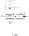
- FIG. 2 is a block diagram illustrating a main part of a frequency compensation clock in a general distributed control system, which has the same construction as disclosed in the reference [1].
- the frequency compensation clock includes a frequency compensation module 210 and a clock counter 220.
- the frequency compensation module 210 may include a frequency multiplier 214 and a frequency compensation value register 212. Before a local oscillator frequency is provided to the clock counter 220, it is multiplied to a frequency compensation value in the frequency compensation module 210, and thus the frequency is corrected.
- clocks with this construction can compensate for both a time offset and a frequency by properly updating a frequency.
- an initial value of the frequency compensation value may be scheme-dependent.
- a frequency compensation value may be set to 1, differently from reference [1], but which neither has an effect on an operation process nor leads to another result.
- the master transmits a sync to the slave.
- the corresponding sync includes the time value MasterSyncTime n by the time-stamping.
- the 'n' corresponds to a count value of the sync.
- the slave receives the sync when its own local clock is SlaveClockTime n .
- the slave computes master clock time MasterClockTime n as expressed by an equation below.
- MasterClockTime n MasterSyncTime n + MasterToSlaveDelay
- the MasterToSlaveDelay corresponds to a transmission delay time value.
- MasterClockCount n MasterClockTime n ⁇ MasterClockTime n ⁇ 1
- a slave clock count SlaveClockCount n for the current synchronization cycle is determined as expressed by an equation below.
- SlaveClockCount n SlaveClockTime n ⁇ SlaveClockTime n ⁇ 1
- ClockDiffCount n MasterClockTime n ⁇ SlaveClockTime n
- FreqScaleFactor n The frequency scaling factor of the slave clock, FreqScaleFactor n is determined as expressed by an equation below.
- FreqScaleFactor n MasterClockCount n + ClockDiffCount n / Slave ClockCount n
- FreqCompValue n FreqScaleFactor n * FreqCompValue n ⁇ 1
- the manner as described above is used in current frequency compensation clocks compensating for both the frequency and the time offset.
- the process for computing the frequency scaling factor is a key point in the manner.
- IEEE 1588 defines the precision time protocol (PTP) to synchronize "clocks" over a network.
- PTP precision time protocol
- the IEEE 1588 PTP has a SYNC message, which is a message from a master clock to slave clocks, broadcasted at fixed intervals of time called "sync intervals".
- Each SYNC message carries the SYNC transmission time step T SYNC,Mk in the master clock time reference for the k-th sync interval. It is received at time T SYNC,Sk in the slave clock time reference. Offset calculation takes place every sync interval and any offset compensation generates a step variation in the slave clock value
- the present invention has been made to solve the above-mentioned problems occurring in the prior art and provides additional advantages. It is the object of the present invention to provide a method for time synchronization, which can improve the synchronization performance by considerably reducing a synchronization error in a distributed control system.
- FIG. 3 is a flow diagram illustrating a basic operation for showing a Time offset Compensation Interval (TCI) and a Frequency Compensation Interval (FCI) for time synchronization in a distributed control system according to one embodiment of the present invention.
- TCI Time offset Compensation Interval
- FCI Frequency Compensation Interval
- a master clock periodically transmits a sync including its own launching time to a slave clock, thereby performing an operation for time synchronization at regular intervals.
- the present invention uses a basic procedure of an IEEE 1588 including communication of a sync, a follow-up, a delay request, and a delay response.
- a frequency update scheme in a slave clock according to the present invention separately compensates for a time offset and a frequency, differently from a conventional scheme of simultaneously compensating for both a time offset and a frequency.
- the TCI corresponds to an interval between two adjacent syncs.
- the FCI is longer than the TCI, e.g. it may be set as a plurality of TCIs.
- parameter 'm' is the ratio of the TCI with respect to the FCI.
- the parameter 'm' may also be set to be time sensitive, and this may be preset in a simpler manner or preset as a properly fixed value in an actual application.
- the present invention provides a manner for computing two frequency scaling factors as an operation procedure for a slave clock, according to the two intervals the TCI and the FCI, as described above.
- n th sync current sync
- m n th sync the slave updates its own frequency in order to compensate for both a time offset and a frequency by using the frequency scaling factor calculation scheme, as expressed by equation 3.
- equation 3 may be expressed by equation 4 below.
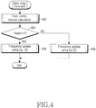
- FIG. 4 is a flow diagram illustrating the time synchronization operation in the slave of the distributed control system according to one embodiment of the present invention.
- the slave if the slave receives the sync, the slave first computes the FCI according to the reception time point of the corresponding sync in step 402.
- the slave determines if the computed FCI corresponds to a preset FCI. That is, the slave determines if the current received sync is an m th sync from a simultaneous compensation time point of previous frequency and time offset.
- the slave updates its own frequency in order to compensate for both the time offset and the frequency using the scaling factor calculation scheme according to equation 3, in step 406.
- the slave updates its own frequency in order to compensate only for time offset by using the scaling factor calculation scheme as expressed by equation 2, in step 408.
- FIG. 5 is a graph illustrating a comparison between time synchronization performance according to the present invention and prior art time synchronization performance, which illustrates the simulation results obtained by comparing the conventional scheme with the scheme of the present invention.
- the simulated system corresponds to a chain of eight nodes indexed 0 to 7.
- a node 0 is a grand master, and a node i is a master of a node (i+1).
- Time is hierarchically synchronized hop-by-hop from the node 0 to the node 7.
- the grand master has a precise oscillator frequency of a 25MHz. Oscillator frequencies in other nodes are optionally selected within the range of 25 MHz ⁇ 50ppm.
- Synchronization interval time is one seconds in case of using the conventional scheme. If the scheme of the present invention is used, the TCI is 1/8 second and the FCI is one second. This represents that m is preset and fixed to eight. Each node outputs a pulse indicator every one second. The pulse referred as a first indicator is used for the synchronization performance test herein.
- the difference of the first indicator output time between the grand master (node 0) and each slave (nodes 1 to 7) is monitored and recorded for statistical analysis.
- the last time of the simulation is 3000 seconds in order to eliminate an unexpected error.
- a standard deviation analyzed for dispersion difference of the first indicator is expressed on a vertical axis in the graph of FIG. 5
- the hop number is expressed on a horizontal axis therein.
- FIG. 5 when the conventional synchronization scheme is used, synchronization errors exponentially increase as the hierarchical hop number increases as expressed by the dotted lines in the graph.
- the expression curve of synchronization errors has a very small slope as expressed by solid lines in the graph.
- a time synchronization scheme in a distributed control system separately compensates for the frequency and the time offset of a slave by using technique of separately compensating for the frequency and the time offset, thereby compensating for most errors accumulated along synchronization paths from a grand master to the slave in a network having hierarchical bridges (switches).
Landscapes
- Engineering & Computer Science (AREA)
- Computer Networks & Wireless Communication (AREA)
- Signal Processing (AREA)
- Synchronisation In Digital Transmission Systems (AREA)
- Small-Scale Networks (AREA)
- Selective Calling Equipment (AREA)
Claims (7)
- Procédé de synchronisation temporelle dans le côté esclave d'un système numérique de contrôle-commande, le procédé comportant les étapes consistant à :lorsqu'un message de synchronisation est reçu en provenance d'un côté maître, confirmer un instant de réception du message de synchronisation correspondant et un instant d'une compensation de fréquence précédente,caractérisé en ce qu'il comporte en outre les étapes consistant à :lorsqu'un message de synchronisation est reçu en provenance d'un côté maître, déterminer (402, 404) si un intervalle entre deux instants correspond à un intervalle de compensation de fréquence préréglé ;réaliser (408) uniquement une opération de compensation de décalage temporel quand l'intervalle résultant entre les deux instants ne correspond pas à l'intervalle de compensation de fréquence préréglé ; etréaliser (406) à la fois une opération de compensation de décalage temporel et une opération de compensation de fréquence quand l'intervalle résultant entre les deux instants correspond à l'intervalle de compensation de fréquence préréglé.
- Procédé selon la revendication 1, dans lequel, lors de l'étape consistant à déterminer si l'intervalle résultant entre les deux instants correspond à l'intervalle de compensation de fréquence préréglé, quand le message de synchronisation reçu est un message de synchronisation d'une séquence préréglée d'un instant précédent de compensation simultanée du décalage temporel et de la fréquence, le résultat est considéré comme correspondant à l'intervalle de compensation de fréquence préréglé.
- Procédé selon la revendication 1, dans lequel,
l'opération de compensation de décalage temporel est réalisé lors d'un intervalle de compensation de décalage temporel conformément à un intervalle de réception du message de synchronisation correspondant ; et
l'intervalle de compensation de fréquence préréglé est plus grand que l'intervalle de compensation de décalage temporel. - Procédé selon la revendication 1, dans lequel la mise en oeuvre uniquement de l'opération de compensation de décalage temporel comporte la mise à jour par le côté esclave de sa propre fréquence en utilisant le message de synchronisation reçu uniquement pour la compensation de décalage temporel ; et
où la mise en oeuvre à la fois de la compensation de décalage temporel et de la compensation de fréquence comporte la mise à jour par le côté esclave de sa propre fréquence en utilisant le message de synchronisation reçu et un message de synchronisation reçu précédemment pour la compensation du décalage temporel et la compensation de la fréquence. - Procédé selon la revendication 4, dans lequel, lors de l'étape de mise à jour par le côté esclave de sa propre fréquence uniquement pour la compensation de décalage temporel, un facteur d'échelle de fréquence « FreqScaleFactor » est calculé en utilisant l'équation ci-dessous conformément au protocole IEEE 1588, et une valeur de compensation de fréquence pour mettre à jour la fréquence est calculé en utilisant le facteur d'échelle de fréquence calculé,

- Procédé selon la revendication 4, dans lequel, lors de l'étape de mise à jour par le côté esclave de sa propre fréquence pour la compensation de décalage temporal et la compensation de fréquence, un facteur d'échelle de fréquence « FreqScaleFactor » est calculé en utilisant l'équation ci-dessous conformément au protocole IEEE 1588, et une valeur de compensation de fréquence pour mettre à jour la fréquence est calculé en utilisant le facteur d'échelle de fréquence calculé,

- Dispositif pour mettre en oeuvre une synchronisation temporelle dans un côté esclave d'un système numérique de contrôle-commande, où ledit dispositif comporte des moyens pour mettre en oeuvre les étapes du procédé selon l'une des revendications 1 à 6.
Applications Claiming Priority (1)
| Application Number | Priority Date | Filing Date | Title |
|---|---|---|---|
| KR1020060039606A KR100735230B1 (ko) | 2006-05-02 | 2006-05-02 | 분산 제어 시스템에서의 타임 동기화 방법 |
Publications (3)
| Publication Number | Publication Date |
|---|---|
| EP1852990A2 EP1852990A2 (fr) | 2007-11-07 |
| EP1852990A3 EP1852990A3 (fr) | 2011-12-21 |
| EP1852990B1 true EP1852990B1 (fr) | 2018-08-22 |
Family
ID=38191218
Family Applications (1)
| Application Number | Title | Priority Date | Filing Date |
|---|---|---|---|
| EP07105955.4A Ceased EP1852990B1 (fr) | 2006-05-02 | 2007-04-11 | Dispositif et procédé pour la synchronisation horaire dans un système de commande distribuée |
Country Status (4)
| Country | Link |
|---|---|
| US (1) | US7831000B2 (fr) |
| EP (1) | EP1852990B1 (fr) |
| KR (1) | KR100735230B1 (fr) |
| CN (1) | CN101068128B (fr) |
Families Citing this family (20)
| Publication number | Priority date | Publication date | Assignee | Title |
|---|---|---|---|---|
| KR100735230B1 (ko) * | 2006-05-02 | 2007-07-03 | 삼성전자주식회사 | 분산 제어 시스템에서의 타임 동기화 방법 |
| KR100876776B1 (ko) * | 2007-04-17 | 2009-01-09 | 삼성전자주식회사 | 통신 시스템에서 gps 정보를 이용한 시간 동기화 방법및 장치 |
| CN101252429B (zh) * | 2008-02-22 | 2010-09-22 | 浙江大学 | 一种提高分布式网络系统中时钟同步精度的方法 |
| CN101738600B (zh) * | 2008-11-14 | 2012-05-30 | 武汉大学 | 高频地波雷达组网的时钟同步控制装置 |
| CN101527608B (zh) * | 2009-04-22 | 2012-01-11 | 哈尔滨工业大学 | 基于网络化测控lxi系统的ieee1588同步精度测试装置 |
| US8363680B2 (en) | 2009-10-29 | 2013-01-29 | Precision Microdynamics, Inc. | Network control architecture and protocol for a distributed control, data acquisition and data distribution system and process |
| CA2691023C (fr) | 2010-01-26 | 2017-01-03 | Ruggedcom Inc. | Methode, dispositif et systeme de conversion de format temporel |
| CN101977104B (zh) * | 2010-11-13 | 2013-01-09 | 上海交通大学 | 基于ieee1588精确时钟同步协议系统及其同步方法 |
| CN102821114B (zh) * | 2011-06-07 | 2017-02-08 | 南京中兴新软件有限责任公司 | 分布式存储系统及其时间戳的实现方法 |
| US8913632B2 (en) * | 2011-08-05 | 2014-12-16 | Khalifa University Of Science, Technology And Research | Method and system for frequency synchronization |
| EP2568631B1 (fr) * | 2011-09-09 | 2018-04-25 | Siemens Aktiengesellschaft | Procédé de transmission de messages de synchronisation dans un réseau de communication |
| US9547333B2 (en) | 2013-10-10 | 2017-01-17 | General Electric Company | System and method for synchronizing networked components |
| JP6626015B2 (ja) * | 2017-01-04 | 2019-12-25 | 株式会社東芝 | 同期装置、同期方法、同期プログラム、および同期システム |
| CN107104749A (zh) * | 2017-04-05 | 2017-08-29 | 北京航天自动控制研究所 | 时钟同步方法及装置 |
| US10727966B1 (en) * | 2017-08-30 | 2020-07-28 | Amazon Technologies, Inc. | Time synchronization with distributed grand master |
| JP6845522B2 (ja) * | 2018-08-06 | 2021-03-17 | 国立研究開発法人情報通信研究機構 | 情報通信システム、情報通信装置 |
| CN109213665B (zh) * | 2018-09-07 | 2020-08-25 | 北京航空航天大学 | 一种分布式并发加速测试技术与平台的构建方法 |
| CN109379500B (zh) * | 2018-11-01 | 2021-08-10 | 厦门亿联网络技术股份有限公司 | 一种基于以太网的级联会议电话装置及方法 |
| CN114520703B (zh) * | 2020-11-19 | 2023-12-29 | 中国科学院沈阳自动化研究所 | 用于工业网络设备间时间同步的时钟漂移补偿方法及电路 |
| CN114640415B (zh) * | 2022-02-28 | 2024-09-03 | 上海安路信息科技股份有限公司 | 时钟漂移补偿方法、装置、终端设备及存储介质 |
Family Cites Families (11)
| Publication number | Priority date | Publication date | Assignee | Title |
|---|---|---|---|---|
| JPH09319407A (ja) * | 1996-05-29 | 1997-12-12 | Mitsubishi Heavy Ind Ltd | 分散システムの時刻同期方法 |
| US6278718B1 (en) * | 1996-08-29 | 2001-08-21 | Excel, Inc. | Distributed network synchronization system |
| US6665316B1 (en) | 1998-09-29 | 2003-12-16 | Agilent Technologies, Inc. | Organization of time synchronization in a distributed system |
| US7251199B2 (en) | 2001-12-24 | 2007-07-31 | Agilent Technologies, Inc. | Distributed system time synchronization including a timing signal path |
| AU2003215841A1 (en) * | 2002-04-30 | 2003-11-17 | International Business Machines Corporation | Method and arrangement for local synchronization in master-slave distributed communication systems |
| US7058089B2 (en) * | 2004-02-18 | 2006-06-06 | Rosemount, Inc. | System and method for maintaining a common sense of time on a network segment |
| JP2005269369A (ja) * | 2004-03-19 | 2005-09-29 | Gkb Technology Kk | 周波数ホッピング方式のデータ通信における時間同期方法 |
| US7409022B2 (en) * | 2004-10-01 | 2008-08-05 | Mitsubishi Electric Research Laboratories, Inc. | Synchronizing clocks in wireless personal area networks |
| KR100735230B1 (ko) * | 2006-05-02 | 2007-07-03 | 삼성전자주식회사 | 분산 제어 시스템에서의 타임 동기화 방법 |
| KR100895175B1 (ko) * | 2007-04-04 | 2009-05-04 | 삼성전자주식회사 | 통신 시스템에서 gps 정보를 이용한 시간 동기화 방법및 장치 |
| KR100876776B1 (ko) * | 2007-04-17 | 2009-01-09 | 삼성전자주식회사 | 통신 시스템에서 gps 정보를 이용한 시간 동기화 방법및 장치 |
-
2006
- 2006-05-02 KR KR1020060039606A patent/KR100735230B1/ko not_active Expired - Fee Related
-
2007
- 2007-01-11 US US11/652,226 patent/US7831000B2/en active Active
- 2007-03-29 CN CN2007100913081A patent/CN101068128B/zh not_active Expired - Fee Related
- 2007-04-11 EP EP07105955.4A patent/EP1852990B1/fr not_active Ceased
Non-Patent Citations (1)
| Title |
|---|
| None * |
Also Published As
| Publication number | Publication date |
|---|---|
| EP1852990A2 (fr) | 2007-11-07 |
| KR100735230B1 (ko) | 2007-07-03 |
| CN101068128A (zh) | 2007-11-07 |
| EP1852990A3 (fr) | 2011-12-21 |
| US20070258550A1 (en) | 2007-11-08 |
| CN101068128B (zh) | 2011-06-01 |
| US7831000B2 (en) | 2010-11-09 |
Similar Documents
| Publication | Publication Date | Title |
|---|---|---|
| US7831000B2 (en) | Method for time synchronization in distributed control system | |
| Jasperneite et al. | Enhancements to the time synchronization standard IEEE-1588 for a system of cascaded bridges | |
| EP2342850B1 (fr) | Procédé de synchronisation d'horloges dans un réseau de communication | |
| US7848360B2 (en) | Method for transmitting synchronization messages in a communication network | |
| US8018972B2 (en) | Timing over packet performance | |
| US20070260906A1 (en) | Clock synchronization method and apparatus | |
| US11522627B2 (en) | TSN enabled controller | |
| JPH10509294A (ja) | データ入出力間に予め設定されたタイミング関係を設けたシステム並びにこのようなシステムの送信機及び受信機 | |
| EP2512048A2 (fr) | Système et procédé pour éviter l'accumulation de gigue à basse fréquence en vue d'obtenir une distribution d'horloge de précision dans de vastes réseaux | |
| US10505652B2 (en) | Methods and systems for estimating offset skew and drift | |
| CN108599885B (zh) | 高精度时间同步方法 | |
| Ronen et al. | Enhanced synchronization accuracy in IEEE1588 | |
| EP2424136A1 (fr) | Système et procédé pour obtenir une synchronisation temporelle dans un réseau de communication | |
| Pahlevan et al. | Simulation framework for clock synchronization in time sensitive networking | |
| CN102710359B (zh) | 一种基于ieee1588的精确时钟频率同步方法及装置 | |
| CN118573313A (zh) | 时钟同步方法及装置 | |
| CN116865890A (zh) | 一种高精度网络授时系统及其服务与评估方法 | |
| Yang et al. | Clock drift and time error compensation with neural network for time synchronization in tsn | |
| Bailleul et al. | Assessing a precise gPTP simulator with IEEE802. 1AS hardware measurements | |
| EP2282427B1 (fr) | Procédé pour la synchronisation de la fréquence d'une horloge client avec la fréquence d'une horloge serveur | |
| EP4075690A1 (fr) | Détermination d'un temps de résidence dans une partie d'un réseau | |
| JP4535288B2 (ja) | 分散制御システム | |
| EP2615752B1 (fr) | Calcul d'une différence de délai dans un réseau optique | |
| EP3732806B1 (fr) | Procédé, dispositif et système d'estimation de décalage, d'obliquité et de dérive | |
| EP3068076A1 (fr) | Détermination automatique de retard asymétrique dans des réseaux de transmission |
Legal Events
| Date | Code | Title | Description |
|---|---|---|---|
| PUAI | Public reference made under article 153(3) epc to a published international application that has entered the european phase |
Free format text: ORIGINAL CODE: 0009012 |
|
| 17P | Request for examination filed |
Effective date: 20070411 |
|
| AK | Designated contracting states |
Kind code of ref document: A2 Designated state(s): AT BE BG CH CY CZ DE DK EE ES FI FR GB GR HU IE IS IT LI LT LU LV MC MT NL PL PT RO SE SI SK TR |
|
| AX | Request for extension of the european patent |
Extension state: AL BA HR MK YU |
|
| PUAL | Search report despatched |
Free format text: ORIGINAL CODE: 0009013 |
|
| AK | Designated contracting states |
Kind code of ref document: A3 Designated state(s): AT BE BG CH CY CZ DE DK EE ES FI FR GB GR HU IE IS IT LI LT LU LV MC MT NL PL PT RO SE SI SK TR |
|
| AX | Request for extension of the european patent |
Extension state: AL BA HR MK RS |
|
| RIC1 | Information provided on ipc code assigned before grant |
Ipc: G06F 1/14 20060101ALI20111115BHEP Ipc: H04J 3/06 20060101AFI20111115BHEP Ipc: H04L 12/56 20060101ALN20111115BHEP |
|
| AKX | Designation fees paid |
Designated state(s): DE FR GB |
|
| RAP1 | Party data changed (applicant data changed or rights of an application transferred) |
Owner name: SAMSUNG ELECTRONICS CO., LTD. |
|
| GRAP | Despatch of communication of intention to grant a patent |
Free format text: ORIGINAL CODE: EPIDOSNIGR1 |
|
| RIC1 | Information provided on ipc code assigned before grant |
Ipc: H04J 3/06 20060101AFI20180206BHEP Ipc: G06F 1/14 20060101ALI20180206BHEP |
|
| INTG | Intention to grant announced |
Effective date: 20180309 |
|
| GRAS | Grant fee paid |
Free format text: ORIGINAL CODE: EPIDOSNIGR3 |
|
| GRAA | (expected) grant |
Free format text: ORIGINAL CODE: 0009210 |
|
| AK | Designated contracting states |
Kind code of ref document: B1 Designated state(s): DE FR GB |
|
| REG | Reference to a national code |
Ref country code: GB Ref legal event code: FG4D |
|
| REG | Reference to a national code |
Ref country code: DE Ref legal event code: R096 Ref document number: 602007055817 Country of ref document: DE |
|
| PGFP | Annual fee paid to national office [announced via postgrant information from national office to epo] |
Ref country code: GB Payment date: 20190321 Year of fee payment: 13 |
|
| REG | Reference to a national code |
Ref country code: DE Ref legal event code: R097 Ref document number: 602007055817 Country of ref document: DE |
|
| PLBE | No opposition filed within time limit |
Free format text: ORIGINAL CODE: 0009261 |
|
| STAA | Information on the status of an ep patent application or granted ep patent |
Free format text: STATUS: NO OPPOSITION FILED WITHIN TIME LIMIT |
|
| 26N | No opposition filed |
Effective date: 20190523 |
|
| PGFP | Annual fee paid to national office [announced via postgrant information from national office to epo] |
Ref country code: DE Payment date: 20190320 Year of fee payment: 13 |
|
| PG25 | Lapsed in a contracting state [announced via postgrant information from national office to epo] |
Ref country code: FR Free format text: LAPSE BECAUSE OF NON-PAYMENT OF DUE FEES Effective date: 20190430 |
|
| REG | Reference to a national code |
Ref country code: DE Ref legal event code: R119 Ref document number: 602007055817 Country of ref document: DE |
|
| PG25 | Lapsed in a contracting state [announced via postgrant information from national office to epo] |
Ref country code: DE Free format text: LAPSE BECAUSE OF NON-PAYMENT OF DUE FEES Effective date: 20201103 |
|
| GBPC | Gb: european patent ceased through non-payment of renewal fee |
Effective date: 20200411 |
|
| PG25 | Lapsed in a contracting state [announced via postgrant information from national office to epo] |
Ref country code: GB Free format text: LAPSE BECAUSE OF NON-PAYMENT OF DUE FEES Effective date: 20200411 |