EP1853128B1 - Versteckte zugschnuranordnung - Google Patents
Versteckte zugschnuranordnung Download PDFInfo
- Publication number
- EP1853128B1 EP1853128B1 EP06721035A EP06721035A EP1853128B1 EP 1853128 B1 EP1853128 B1 EP 1853128B1 EP 06721035 A EP06721035 A EP 06721035A EP 06721035 A EP06721035 A EP 06721035A EP 1853128 B1 EP1853128 B1 EP 1853128B1
- Authority
- EP
- European Patent Office
- Prior art keywords
- drawstring
- housing
- hidden
- arm
- pin
- Prior art date
- Legal status (The legal status is an assumption and is not a legal conclusion. Google has not performed a legal analysis and makes no representation as to the accuracy of the status listed.)
- Expired - Lifetime
Links
Images
Classifications
-
- A—HUMAN NECESSITIES
- A41—WEARING APPAREL
- A41F—GARMENT FASTENINGS; SUSPENDERS
- A41F1/00—Fastening devices specially adapted for garments
-
- A—HUMAN NECESSITIES
- A41—WEARING APPAREL
- A41D—OUTERWEAR; PROTECTIVE GARMENTS; ACCESSORIES
- A41D2200/00—Components of garments
- A41D2200/20—Hoods
-
- Y—GENERAL TAGGING OF NEW TECHNOLOGICAL DEVELOPMENTS; GENERAL TAGGING OF CROSS-SECTIONAL TECHNOLOGIES SPANNING OVER SEVERAL SECTIONS OF THE IPC; TECHNICAL SUBJECTS COVERED BY FORMER USPC CROSS-REFERENCE ART COLLECTIONS [XRACs] AND DIGESTS
- Y10—TECHNICAL SUBJECTS COVERED BY FORMER USPC
- Y10T—TECHNICAL SUBJECTS COVERED BY FORMER US CLASSIFICATION
- Y10T24/00—Buckles, buttons, clasps, etc.
- Y10T24/37—Drawstring, laced-fastener, or separate essential cooperating device therefor
- Y10T24/3703—Includes separate device for holding drawn portion of lacing
- Y10T24/3713—Includes separate device for holding drawn portion of lacing having relatively movable holding components or surfaces
Definitions
- This invention relates generally to drawstrings for use in apparel and other objects, and, in particular, to a hidden drawstring assembly for use in apparel and other objects.
- Drawstrings are well known for closing or tightening items such as articles of apparel and duffle bags. When drawstrings are used on a hood of a coat or jacket, for example, the hanging drawstring can be cumbersome and an annoyance, and may create a safety issue due to the drawstring getting caught in or on another object. This can be especially dangerous for children.
- United States patent application published as US 2003/0204970 discloses a lace tightening assembly on a footwear body including a base, a spool, a pull string, and a restricting unit. The base is mounted to the footwear body. The spool is mounted rotatably on the base.
- the pull string has a fixing portion secured to the spool, an intermediate portion connected to the fixing portion and wound on the spool, and a connecting portion connection to the intermediate portion and provided with a ring unit.
- the restricting unit restricts rotation of the spool relative to the base.
- the principles of the invention may be used to advantage to provide a hidden drawstring assembly that can be used to tighten a drawstring, and which allows the drawstring to be bidden, thereby preventing free ends of the drawstring from being exposed and minimizing the danger associated with free or loose drawstring ends.
- the present invention providers a drawstring apparatus as defined in the appending claims.
- Substantial advantage is achieved by providing a hidden drawstring assembly.
- certain preferred embodiments of the present invention provide an apparatus that allows a drawstring to be tightened, while keeping a free end of the drawstring concealed. This is highly advantageous since it prevents the free end from being exposed, minimizing the danger of the drawstring getting caught or snagged on or in another object. This is especially advantageous for use on children's apparel.
- FIG. 1 is a perspective view of a hidden drawstring assembly in accordance with a preferred embodiment of the present invention, shown in use on a hood of an article of apparel.
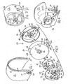
- FIG. 2 is an exploded view of the drawstring assembly of FIG. 1 .
- FIG. 3 is a perspective view of the hub of the drawstring assembly of FIG. 1 .
- FIG. 4 a perspective view, shown partially broken away, of a portion of the drawstring assembly of FIG. 1 , shown installed in the hood of FIG. 1 .
- FIG. 1 A preferred embodiment of a hidden drawstring assembly 10 is shown in FIG. 1 .
- Hidden drawstring assembly 10 is shown here in use on a hood 12 of an article of apparel.
- apparel includes footwear.
- the hidden drawstring assembly of the present invention is not intended to be limited to use in apparel and can be used in any suitable device.
- a hidden drawstring assembly 10 may be used in a bag, such as a duffel bag or backpack.
- Other suitable applications will become readily apparent to those skilled in the art, given the benefit of this disclosure.
- a drawstring 14 extends about a periphery of hood 12, with a first end 16 (not visible here) of drawstring 14 secured to drawstring assembly 10 and a second end 18 of drawstring 14 secured to hood 12 by stitching or other suitable means.
- Drawstring 14 is concealed within hood 12.
- drawstring 14 is located in a sleeve 19 formed in hood 12.
- Sleeve 19 may be formed by folding over and securing an edge of hood 12 by stitching or other suitable means.
- sleeve 19 may be formed by a pair of opposed lines of stitching extending along the edge of hood 12.
- a strip of material may be secured to hood 12 by stitching or other suitable means to form sleeve 19.
- Drawstring 14 is advantageously hidden within hood 12 and drawstring assembly 10 such that its ends do not hang free both when drawstring is tightened and when it is in its loose configuration, thereby minimizing any risk of the drawstring getting caught on another object.
- Drawstring assembly 10 is seen in greater detail in FIG. 2 in exploded fashion.
- Drawstring assembly 10 includes a housing 22 formed of a first portion 24 and a second portion 26.
- a first aperture 28 in housing 22 (seen in FIG. 1 and 4 ) is formed by an aperture 30 in a radially outward wall 32 of first portion 24 and a mating aperture 34 in a radially outward wall 36 of second portion 26.
- Second portion 26 is nested within first portion 24 such that aperture 30 and aperture 34 align to define first aperture 28.
- a plurality of apertures 38 are formed in wall 32 of first portion 24.
- a plurality of pairs of slots 40 are formed in wall 36 of second portion 26. Each pair of slots 40 extends axially inwardly from an axially exterior edge of wall 36 to define a flexible arm 42.
- a projection 44 is formed on a radially outward surface of each flexible arm 42. Each projection 44 is received in a corresponding aperture 38 when second portion 26 is nested within first portion 24. Flexible arms 42 move radially, allowing projections 44 to be released from engagement with apertures 38.
- first portion 24 and second portion 26 To separate first portion 24 and second portion 26 from one another, a user simply presses projections 44 radially inwardly with their finger or a pin, rod or other suitable member, thereby releasing projections 44 from engagement with apertures 38, allowing first portion 24 and second portion 26 to be pulled apart from one another.
- a second aperture 46 is formed in a central portion of an axially outward wall 48 of first portion 24.
- a plurality of locking apertures 50 is disposed about second aperture 46.
- a hub 52 is positioned within second portion 26 and includes a drive pin seat 54.
- a drawstring aperture 56 is formed in a radially outward wall 58 of hub 52.
- Drawstring aperture 56 receives first end 16 of drawstring 14.
- First end 16 may be anchored to hub 52 by a knot tied in its end (not shown) or any other suitable fastening means.
- Drawstring 14 is wound about hub 52 as drawstring 14 is tightened about hood 12, as described in greater detail below.
- a cylindrical wall 58 of hub 52 extends from a base 60.
- Interior walls 64 extend radially inwardly from wall 58 to drive pin seat 54.
- Drive pin seat 54 receives a drive pin 68 of handle assembly 20 as described in greater detail below.
- drive pin seat 54 is substantially rectangular in shape. It is to be appreciated that drive pin seat 54 may have any shape that mates with and receives drive pin 68.
- slots 40, flexible arms 42 and projections 44 can be positioned on first portion 24 with apertures 38 formed in second portion 26.
- housing 22 and, therefore, first portion 24 and second portion 26, are substantially cylindrical.
- other shapes of housing 22 are considered to be within the scope of the present invention.
- Handle assembly 20 seen in FIG. 2 , includes a handle housing 70 and a handle portion 72.
- Handle portion 72 includes a base portion 74 and an arm 76 pivotally secured to base portion 74.
- Base portion 74 includes a recess 77 into which arm 76 may be folded.
- arm 76 is folded into a compact configuration within base portion 74.
- Arm 76 may be pivotally secured to base portion 74 by way of a pin 78 extending through an aperture 80 in a first end 82 of drive pin 68.
- Drive pin 68 extends through an aperture 84 in base portion 74 and through an aperture 86 in handle housing 70.
- a second end 88 of drive pin 68 extends through second aperture 46 in first portion 24 of housing 22 and is received in drive pin seat 54 of hub 52.
- a pair of pins 90 extends outwardly from arm 76. Pins 90 are received in notches 92 formed in walls of recess 77. In a preferred embodiment, pins 90 are spring-loaded such that they are biased outwardly into engagement with notches 92 when arm 76 is folded into recess 77. Thus, in a non-operating condition, arm 76 is locked in place with respect to base portion 74. A release button 94 in arm 76 is connected to spring-loaded pins 90 such that depressing release button relieves the biasing action on pins 90 and allows arm 76 to be pivoted outwardly from base portion 74. It is to be appreciated that in certain preferred embodiments a single pin 90 can be provided on arm 76.
- a first end 96 of a spring-loaded locking pin 98 extends through an aperture 100 in base portion 74.
- Locking pin 98 extends through an aperture 102 in handle housing 70, with a second end 104 of locking pin 98 extending through any one of locking apertures 50 in first portion 24 of housing 22 into hub 54.
- Second end 104 abuts against interior walls 64 of hub 54 to prevent rotation of hub 54 and unwinding of drawstring 14 when handle assembly 20 is in a locked condtion.
- the spring 99 biasing pin 98 outwardly is contained within handle housing 70.
- arm 76 After arm 76 has been rotated a sufficient amount to place drawstring 14 in a desired tightened position, arm 76 is folded back into recess 76, thereby depressing locking pin 98 such that its second end 104 engages a corresponding locking aperture 50.
- a plurality of pins 105 extend outwardly from base portion 74 and are received in corresponding recesses 107 formed in handle housing 70, thereby securing base portion 74 to handle housing 70.
- Pins 105 may include barbs 109 on ends thereof, which are received in recesses 110 formed in the wall of handle housing 70.
- a pin, rod or other suitable member may be inserted into recesses 110 to release barbs 109 and pins 105, allowing base portion 74 to be separated from handle housing 70.
- a portion of the fabric of hood 12 (or the material of any other object to which hidden drawstring assembly 10 is attached) is captured between base portion 74 and handle housing 70, thereby securing hidden drawstring assembly 10 to hood 12.
- a guide member such as a roller bar 106 is supported by a pair of flanges 108 extending outwardly from first portion 24 of housing 22.
- Drawstring 14 exits aperture 28 in housing 22 and wraps around roller bar 106, reducing the chance of drawstring 14 getting hung up on the edge of aperture 28.
Landscapes
- Engineering & Computer Science (AREA)
- Textile Engineering (AREA)
- Professional, Industrial, Or Sporting Protective Garments (AREA)
- Aiming, Guidance, Guns With A Light Source, Armor, Camouflage, And Targets (AREA)
- Purses, Travelling Bags, Baskets, Or Suitcases (AREA)
- Storing, Repeated Paying-Out, And Re-Storing Of Elongated Articles (AREA)
- Emergency Lowering Means (AREA)
- Train Traffic Observation, Control, And Security (AREA)
Claims (13)
- Verdeckte Zugschnurvorrichtung (10), welche in Kombination aufweist:ein Bekleidungsstück (12);eine Zugschnur (14), die ein erstes Ende und ein zweites Ende aufweist, wobei das zweite Ende an einem Abschnitt des Kleidungsstücks (12) angebracht ist, wobei die Zugschnur (14) in dem Kleidungsstück (12) verborgen ist;ein Gehäuse (22), das an dem Bekleidungsstück (12) angebracht ist und eine erste Öffnung (28), die eingerichtet ist, die Zugschnur (14) aufzunehmen, eine zweite Öffnung (46), durch welche sich ein Antriebselement (68) erstreckt, und eine Vielzahl von Arretieröffnungen (50), die um die zweite Öffnung (46) herum angeordnet sind, aufweist;eine drehbare Hülse (52), die innerhalb des Gehäuses (22) angeordnet ist, wobei das erste Ende der Zugschnur (14) um die Hülse (52) gewunden ist;eine Griffbaugruppe (20), die drehbar mit dem Gehäuse (22) verbunden ist und einen Arretierstift (98) aufweist, der sich axial nach innen von einer Innenfläche des Griffs (20) erstreckt, wobei der Arretierstift (98) in den Arretieröffnungen (50) aufgenommen werden kann und axial nach außen vorgespannt ist; undein Antriebselement (68), das ein erstes Ende, das mit der Griffbaugruppe (20) verbunden ist, und ein zweites Ende, das mit der drehbaren Hülse (52) verbunden ist, aufweist.
- Verdeckte Zugschnurvorrichtung gemäß Anspruch 1, wobei die Griffbaugruppe (20) einen Basisabschnitt (74) und einen Arm (76), der drehbar an dem Basisabschnitt (74) angebracht ist, aufweist.
- Verdeckte Zugschnurvorrichtung gemäß Anspruch 2, wobei der Arm (76) zumindest einen Stift (90) umfasst und der Basisabschnitt (74) zumindest eine Aussparung (92) umfasst, wobei die zumindest eine Aussparung (92) einen entsprechenden Stift (90) aufnimmt, wenn der Arm (76) in eine angrenzende Beziehung in Bezug auf den Basisabschnitt (74) gedreht wird.
- Verdeckte Zugschnurvorrichtung gemäß Anspruch 3, wobei der zumindest eine Stift (90) nach außen in Bezug auf den Arm (76) vorgespannt ist und der Arm (76) einen Löseschalter (94) umfasst, der mit dem zumindest einen Stift (90) verbunden und eingerichtet ist, den Stift (90) von einem Zustand zu lösen, bei dem dieser nach außen vorgespannt wird.
- Verdeckte Zugschnurvorrichtung gemäß Anspruch 2, wobei Basisabschnitt (74) eine Aussparung (77) umfasst, in welche der Arm (76) gedreht werden kann.
- Verdeckte Zugschnurvorrichtung gemäß Anspruch 1, wobei die Griffbaugruppe (20) weiterhin ein Griffgehäuse (70) aufweist, mit welchem der Basisabschnitt (74) verbunden ist.
- Verdeckte Zugschnurvorrichtung gemäß Anspruch 6, wobei der Basisabschnitt (74) eine Vielzahl von Stiften (105) umfasst und das Griffgehäuse (70) eine Vielzahl von Aussparungen (107) umfasst, wobei jede Aussparung (107) einen entsprechenden Stift (105) aufnimmt, um den Basisabschnitt (74) an dem Griffgehäuse (70) anzubringen.
- Verdeckte Zugschnurvorrichtung gemäß Anspruch 1, wobei das Gehäuse (22) einen ersten Abschnitt (24) und einen zweiten Abschnitt (26), der lösbar an dem ersten Abschnitt (74) angebracht ist, umfasst.
- Verdeckte Zugschnurvorrichtung gemäß Anspruch 8, wobei ein Element aus dem ersten Abschnitt (24) und dem zweiten Abschnitt (26) eine Vielzahl von Vorsprüngen (44) umfasst und das andere Element aus dem ersten Abschnitt (24) und dem zweiten Abschnitt (26) eine Vielzahl von Öffnungen (38) umfasst, wobei jeder Vorsprung (44) lösbar in einer entsprechenden Aussparung (38) aufgenommen ist, um den ersten Abschnitt (24) lösbar an dem zweiten Abschnitt (26) anzubringen.
- Verdeckte Zugschnurvorrichtung gemäß Anspruch 9, wobei das eine Element aus dem ersten Abschnitt (24) und dem zweiten Abschnitt (26) eine Vielzahl von Schlitzpaaren (40) umfasst, die sich radial nach innen von dessen Außenfläche erstrecken, wobei jedes Schlitzpaar (40) einen flexiblen Arm (42) festlegt, wobei jeder Vorsprung (44) an einem entsprechenden flexiblen Arm (42) angeordnet ist.
- Verdeckte Zugschnurvorrichtung gemäß Anspruch 1, weiterhin aufweisend ein Führungselement (106), das an einer Außenseite des Gehäuses (22) benachbart zu der ersten Öffnung (28) angebracht ist.
- Verdeckte Zugschnurvorrichtung gemäß Anspruch 11, wobei das Führungselement (106) eine Rollenstange (106), die sich zwischen einem Flanschpaar (108) erstreckt, das sich nach außen in Bezug auf eine Außenseite des Gehäuses (22) erstreckt, aufweist.
- Verdeckte Zugschnurvorrichtung gemäß Anspruch 1, weiterhin aufweisend eine Feder (99) in dem Griff (20), die den Arretierstift (98) nach außen vorspannt.
Applications Claiming Priority (2)
| Application Number | Priority Date | Filing Date | Title |
|---|---|---|---|
| US11/071,066 US7387272B2 (en) | 2005-03-03 | 2005-03-03 | Hidden drawstring assembly |
| PCT/US2006/006556 WO2006096344A1 (en) | 2005-03-03 | 2006-02-23 | Hidden drawstring assembly |
Publications (2)
| Publication Number | Publication Date |
|---|---|
| EP1853128A1 EP1853128A1 (de) | 2007-11-14 |
| EP1853128B1 true EP1853128B1 (de) | 2010-12-15 |
Family
ID=36616975
Family Applications (1)
| Application Number | Title | Priority Date | Filing Date |
|---|---|---|---|
| EP06721035A Expired - Lifetime EP1853128B1 (de) | 2005-03-03 | 2006-02-23 | Versteckte zugschnuranordnung |
Country Status (7)
| Country | Link |
|---|---|
| US (1) | US7387272B2 (de) |
| EP (1) | EP1853128B1 (de) |
| JP (1) | JP4637186B2 (de) |
| CN (1) | CN100571555C (de) |
| AT (1) | ATE491357T1 (de) |
| DE (1) | DE602006018871D1 (de) |
| WO (1) | WO2006096344A1 (de) |
Families Citing this family (10)
| Publication number | Priority date | Publication date | Assignee | Title |
|---|---|---|---|---|
| DE202006009865U1 (de) * | 2006-06-23 | 2006-08-31 | SALEWA Sportgeräte GmbH | Bekleidungsteil mit mindestens einem Kordelzug |
| US7921522B2 (en) * | 2006-10-30 | 2011-04-12 | Nike, Inc. | Draw cord adjuster |
| KR100895412B1 (ko) * | 2008-07-07 | 2009-05-06 | 소윤서 | 줄 길이 조절장치 |
| US9044068B2 (en) * | 2012-01-05 | 2015-06-02 | Tom Neale | Fastening system and method |
| US8875313B2 (en) * | 2012-10-22 | 2014-11-04 | Pedro Ramirez | Hooded garment with hidden drawstring |
| US10318708B2 (en) | 2013-03-14 | 2019-06-11 | Nike, Inc. | System and method for monitoring athletic activity from multiple body locations |
| CN105293192B (zh) * | 2014-05-28 | 2017-08-29 | 国网山西省电力公司电力科学研究院 | 一种转轴式线缆收纳盒 |
| US9833042B1 (en) | 2015-02-25 | 2017-12-05 | Matthew T. Hauser | Catch mechanism for an elongated member |
| EP3690278B1 (de) | 2016-05-31 | 2022-01-12 | NIKE Innovate C.V. | Kordelsperre |
| JP7503032B2 (ja) * | 2021-08-06 | 2024-06-19 | 株式会社ワークマン | ファン付ウエア |
Family Cites Families (11)
| Publication number | Priority date | Publication date | Assignee | Title |
|---|---|---|---|---|
| US3937415A (en) * | 1973-05-16 | 1976-02-10 | John Prinz | Downrigger |
| US4272036A (en) * | 1978-08-03 | 1981-06-09 | Keson Industries, Inc. | Line reel |
| IT1184177B (it) * | 1985-03-22 | 1987-10-22 | Nordica Spa | Scarpone da sci ad entrata posteriore con bloccaggio della zona della caviglia |
| IT209343Z2 (it) * | 1985-09-04 | 1988-10-05 | Nordica Spa | Struttura di dispositivo di azionamento per elementi di bloccaggio del piede particolarmente per scarponi da sci. |
| US5388877A (en) * | 1993-09-07 | 1995-02-14 | Wenk; Carl J. | Hunting bow retriever |
| US5934599A (en) * | 1997-08-22 | 1999-08-10 | Hammerslag; Gary R. | Footwear lacing system |
| US6289558B1 (en) * | 1997-08-22 | 2001-09-18 | Boa Technology, Inc. | Footwear lacing system |
| US6928703B2 (en) * | 2002-03-25 | 2005-08-16 | Robin Petravic | Sealed slider adjustment mechanism |
| US6675503B2 (en) * | 2002-05-02 | 2004-01-13 | Kun-Chung Liu | Easy-to-wear footwear |
| CN2565281Y (zh) * | 2002-08-14 | 2003-08-13 | 潍坊舒燕女士用品有限公司 | 文胸调节扣 |
| JP4557607B2 (ja) | 2004-06-02 | 2010-10-06 | 株式会社ゴールドウインテクニカルセンター | 摺動式調節具 |
-
2005
- 2005-03-03 US US11/071,066 patent/US7387272B2/en not_active Expired - Lifetime
-
2006
- 2006-02-23 AT AT06721035T patent/ATE491357T1/de not_active IP Right Cessation
- 2006-02-23 CN CNB2006800069392A patent/CN100571555C/zh not_active Expired - Fee Related
- 2006-02-23 EP EP06721035A patent/EP1853128B1/de not_active Expired - Lifetime
- 2006-02-23 DE DE602006018871T patent/DE602006018871D1/de not_active Expired - Lifetime
- 2006-02-23 WO PCT/US2006/006556 patent/WO2006096344A1/en not_active Ceased
- 2006-02-23 JP JP2007558078A patent/JP4637186B2/ja not_active Expired - Lifetime
Also Published As
| Publication number | Publication date |
|---|---|
| CN101193566A (zh) | 2008-06-04 |
| US7387272B2 (en) | 2008-06-17 |
| CN100571555C (zh) | 2009-12-23 |
| ATE491357T1 (de) | 2011-01-15 |
| US20060196022A1 (en) | 2006-09-07 |
| JP4637186B2 (ja) | 2011-02-23 |
| EP1853128A1 (de) | 2007-11-14 |
| JP2008531202A (ja) | 2008-08-14 |
| WO2006096344A1 (en) | 2006-09-14 |
| DE602006018871D1 (de) | 2011-01-27 |
Similar Documents
| Publication | Publication Date | Title |
|---|---|---|
| EP1853128B1 (de) | Versteckte zugschnuranordnung | |
| KR100925760B1 (ko) | 끈 고정장치 | |
| CA2648034C (en) | Eyeglass and other personal items holder | |
| US5829559A (en) | Article for attaching an item to luggage | |
| CN101282667A (zh) | 快速释放扣件 | |
| US5084916A (en) | Necktie assembly | |
| US7921470B2 (en) | Sleeve holder | |
| JP2011115644A (ja) | 安全ハーネス | |
| US20190208748A1 (en) | Retractable leash and collar or harness assembly | |
| US6152395A (en) | Spool assembly for pintle | |
| CA2108046C (en) | Waterproof retractable towel bag | |
| CN109219713A (zh) | 绳锁定件 | |
| US5501029A (en) | Fishing reel cover | |
| US7114223B2 (en) | Covered zipper pull assembly | |
| US20170360008A1 (en) | Self-contained, retractable leash and collar or harness assembly | |
| US9402431B1 (en) | Clothing adjustment device | |
| EP3601128A1 (de) | Wickelvorrichtung zum wickeln eines flexiblen elements davon | |
| JP3287583B2 (ja) | 安全ベルト | |
| JP3107519U (ja) | 結び帯 | |
| KR200489365Y1 (ko) | 벨트 파우치 | |
| JP3106248U (ja) | ショルダーストラップ | |
| CN210169233U (zh) | 伞套 | |
| KR100672284B1 (ko) | 폐구조체에 걸기 위한 엉키지 않는 우산 손잡이 | |
| JP3107655U (ja) | 収納紐付き衣服 | |
| CN101568273B (zh) | 手提袋 |
Legal Events
| Date | Code | Title | Description |
|---|---|---|---|
| PUAI | Public reference made under article 153(3) epc to a published international application that has entered the european phase |
Free format text: ORIGINAL CODE: 0009012 |
|
| 17P | Request for examination filed |
Effective date: 20070827 |
|
| AK | Designated contracting states |
Kind code of ref document: A1 Designated state(s): AT BE BG CH CY CZ DE DK EE ES FI FR GB GR HU IE IS IT LI LT LU LV MC NL PL PT RO SE SI SK TR |
|
| RAP1 | Party data changed (applicant data changed or rights of an application transferred) |
Owner name: NIKE INTERNATIONAL LTD. |
|
| DAX | Request for extension of the european patent (deleted) | ||
| 17Q | First examination report despatched |
Effective date: 20090609 |
|
| GRAP | Despatch of communication of intention to grant a patent |
Free format text: ORIGINAL CODE: EPIDOSNIGR1 |
|
| GRAS | Grant fee paid |
Free format text: ORIGINAL CODE: EPIDOSNIGR3 |
|
| GRAA | (expected) grant |
Free format text: ORIGINAL CODE: 0009210 |
|
| AK | Designated contracting states |
Kind code of ref document: B1 Designated state(s): AT BE BG CH CY CZ DE DK EE ES FI FR GB GR HU IE IS IT LI LT LU LV MC NL PL PT RO SE SI SK TR |
|
| REG | Reference to a national code |
Ref country code: CH Ref legal event code: EP Ref country code: GB Ref legal event code: FG4D |
|
| REG | Reference to a national code |
Ref country code: IE Ref legal event code: FG4D |
|
| REF | Corresponds to: |
Ref document number: 602006018871 Country of ref document: DE Date of ref document: 20110127 Kind code of ref document: P |
|
| REG | Reference to a national code |
Ref country code: NL Ref legal event code: VDEP Effective date: 20101215 |
|
| PG25 | Lapsed in a contracting state [announced via postgrant information from national office to epo] |
Ref country code: LT Free format text: LAPSE BECAUSE OF FAILURE TO SUBMIT A TRANSLATION OF THE DESCRIPTION OR TO PAY THE FEE WITHIN THE PRESCRIBED TIME-LIMIT Effective date: 20101215 |
|
| LTIE | Lt: invalidation of european patent or patent extension |
Effective date: 20101215 |
|
| PG25 | Lapsed in a contracting state [announced via postgrant information from national office to epo] |
Ref country code: AT Free format text: LAPSE BECAUSE OF FAILURE TO SUBMIT A TRANSLATION OF THE DESCRIPTION OR TO PAY THE FEE WITHIN THE PRESCRIBED TIME-LIMIT Effective date: 20101215 Ref country code: BG Free format text: LAPSE BECAUSE OF FAILURE TO SUBMIT A TRANSLATION OF THE DESCRIPTION OR TO PAY THE FEE WITHIN THE PRESCRIBED TIME-LIMIT Effective date: 20110315 Ref country code: FI Free format text: LAPSE BECAUSE OF FAILURE TO SUBMIT A TRANSLATION OF THE DESCRIPTION OR TO PAY THE FEE WITHIN THE PRESCRIBED TIME-LIMIT Effective date: 20101215 Ref country code: SE Free format text: LAPSE BECAUSE OF FAILURE TO SUBMIT A TRANSLATION OF THE DESCRIPTION OR TO PAY THE FEE WITHIN THE PRESCRIBED TIME-LIMIT Effective date: 20101215 Ref country code: SI Free format text: LAPSE BECAUSE OF FAILURE TO SUBMIT A TRANSLATION OF THE DESCRIPTION OR TO PAY THE FEE WITHIN THE PRESCRIBED TIME-LIMIT Effective date: 20101215 Ref country code: NL Free format text: LAPSE BECAUSE OF FAILURE TO SUBMIT A TRANSLATION OF THE DESCRIPTION OR TO PAY THE FEE WITHIN THE PRESCRIBED TIME-LIMIT Effective date: 20101215 Ref country code: LV Free format text: LAPSE BECAUSE OF FAILURE TO SUBMIT A TRANSLATION OF THE DESCRIPTION OR TO PAY THE FEE WITHIN THE PRESCRIBED TIME-LIMIT Effective date: 20101215 Ref country code: CY Free format text: LAPSE BECAUSE OF FAILURE TO SUBMIT A TRANSLATION OF THE DESCRIPTION OR TO PAY THE FEE WITHIN THE PRESCRIBED TIME-LIMIT Effective date: 20101215 |
|
| PG25 | Lapsed in a contracting state [announced via postgrant information from national office to epo] |
Ref country code: CZ Free format text: LAPSE BECAUSE OF FAILURE TO SUBMIT A TRANSLATION OF THE DESCRIPTION OR TO PAY THE FEE WITHIN THE PRESCRIBED TIME-LIMIT Effective date: 20101215 Ref country code: PT Free format text: LAPSE BECAUSE OF FAILURE TO SUBMIT A TRANSLATION OF THE DESCRIPTION OR TO PAY THE FEE WITHIN THE PRESCRIBED TIME-LIMIT Effective date: 20110415 Ref country code: GR Free format text: LAPSE BECAUSE OF FAILURE TO SUBMIT A TRANSLATION OF THE DESCRIPTION OR TO PAY THE FEE WITHIN THE PRESCRIBED TIME-LIMIT Effective date: 20110316 Ref country code: BE Free format text: LAPSE BECAUSE OF FAILURE TO SUBMIT A TRANSLATION OF THE DESCRIPTION OR TO PAY THE FEE WITHIN THE PRESCRIBED TIME-LIMIT Effective date: 20101215 Ref country code: ES Free format text: LAPSE BECAUSE OF FAILURE TO SUBMIT A TRANSLATION OF THE DESCRIPTION OR TO PAY THE FEE WITHIN THE PRESCRIBED TIME-LIMIT Effective date: 20110326 Ref country code: EE Free format text: LAPSE BECAUSE OF FAILURE TO SUBMIT A TRANSLATION OF THE DESCRIPTION OR TO PAY THE FEE WITHIN THE PRESCRIBED TIME-LIMIT Effective date: 20101215 Ref country code: IS Free format text: LAPSE BECAUSE OF FAILURE TO SUBMIT A TRANSLATION OF THE DESCRIPTION OR TO PAY THE FEE WITHIN THE PRESCRIBED TIME-LIMIT Effective date: 20110415 |
|
| PG25 | Lapsed in a contracting state [announced via postgrant information from national office to epo] |
Ref country code: SK Free format text: LAPSE BECAUSE OF FAILURE TO SUBMIT A TRANSLATION OF THE DESCRIPTION OR TO PAY THE FEE WITHIN THE PRESCRIBED TIME-LIMIT Effective date: 20101215 Ref country code: PL Free format text: LAPSE BECAUSE OF FAILURE TO SUBMIT A TRANSLATION OF THE DESCRIPTION OR TO PAY THE FEE WITHIN THE PRESCRIBED TIME-LIMIT Effective date: 20101215 Ref country code: RO Free format text: LAPSE BECAUSE OF FAILURE TO SUBMIT A TRANSLATION OF THE DESCRIPTION OR TO PAY THE FEE WITHIN THE PRESCRIBED TIME-LIMIT Effective date: 20101215 |
|
| PG25 | Lapsed in a contracting state [announced via postgrant information from national office to epo] |
Ref country code: MC Free format text: LAPSE BECAUSE OF NON-PAYMENT OF DUE FEES Effective date: 20110228 |
|
| REG | Reference to a national code |
Ref country code: CH Ref legal event code: PL |
|
| PLBE | No opposition filed within time limit |
Free format text: ORIGINAL CODE: 0009261 |
|
| STAA | Information on the status of an ep patent application or granted ep patent |
Free format text: STATUS: NO OPPOSITION FILED WITHIN TIME LIMIT |
|
| PG25 | Lapsed in a contracting state [announced via postgrant information from national office to epo] |
Ref country code: CH Free format text: LAPSE BECAUSE OF NON-PAYMENT OF DUE FEES Effective date: 20110228 Ref country code: LI Free format text: LAPSE BECAUSE OF NON-PAYMENT OF DUE FEES Effective date: 20110228 Ref country code: DK Free format text: LAPSE BECAUSE OF FAILURE TO SUBMIT A TRANSLATION OF THE DESCRIPTION OR TO PAY THE FEE WITHIN THE PRESCRIBED TIME-LIMIT Effective date: 20101215 |
|
| 26N | No opposition filed |
Effective date: 20110916 |
|
| REG | Reference to a national code |
Ref country code: IE Ref legal event code: MM4A |
|
| PG25 | Lapsed in a contracting state [announced via postgrant information from national office to epo] |
Ref country code: IT Free format text: LAPSE BECAUSE OF FAILURE TO SUBMIT A TRANSLATION OF THE DESCRIPTION OR TO PAY THE FEE WITHIN THE PRESCRIBED TIME-LIMIT Effective date: 20101215 |
|
| REG | Reference to a national code |
Ref country code: DE Ref legal event code: R097 Ref document number: 602006018871 Country of ref document: DE Effective date: 20110916 |
|
| PG25 | Lapsed in a contracting state [announced via postgrant information from national office to epo] |
Ref country code: IE Free format text: LAPSE BECAUSE OF NON-PAYMENT OF DUE FEES Effective date: 20110223 |
|
| PG25 | Lapsed in a contracting state [announced via postgrant information from national office to epo] |
Ref country code: LU Free format text: LAPSE BECAUSE OF NON-PAYMENT OF DUE FEES Effective date: 20110223 |
|
| PG25 | Lapsed in a contracting state [announced via postgrant information from national office to epo] |
Ref country code: TR Free format text: LAPSE BECAUSE OF FAILURE TO SUBMIT A TRANSLATION OF THE DESCRIPTION OR TO PAY THE FEE WITHIN THE PRESCRIBED TIME-LIMIT Effective date: 20101215 |
|
| PG25 | Lapsed in a contracting state [announced via postgrant information from national office to epo] |
Ref country code: HU Free format text: LAPSE BECAUSE OF FAILURE TO SUBMIT A TRANSLATION OF THE DESCRIPTION OR TO PAY THE FEE WITHIN THE PRESCRIBED TIME-LIMIT Effective date: 20101215 |
|
| REG | Reference to a national code |
Ref country code: DE Ref legal event code: R082 Ref document number: 602006018871 Country of ref document: DE Representative=s name: KOTITSCHKE & HEURUNG PARTNERSCHAFT MBB PATENT-, DE |
|
| REG | Reference to a national code |
Ref country code: GB Ref legal event code: 732E Free format text: REGISTERED BETWEEN 20140626 AND 20140702 |
|
| REG | Reference to a national code |
Ref country code: DE Ref legal event code: R082 Ref document number: 602006018871 Country of ref document: DE Representative=s name: KOTITSCHKE & HEURUNG PARTNERSCHAFT MBB PATENT-, DE |
|
| REG | Reference to a national code |
Ref country code: DE Ref legal event code: R082 Ref document number: 602006018871 Country of ref document: DE Representative=s name: KOTITSCHKE & HEURUNG PARTNERSCHAFT MBB PATENT-, DE Effective date: 20150401 Ref country code: DE Ref legal event code: R082 Ref document number: 602006018871 Country of ref document: DE Representative=s name: KOTITSCHKE & HEURUNG PARTNERSCHAFT MBB PATENT-, DE Effective date: 20140109 Ref country code: DE Ref legal event code: R081 Ref document number: 602006018871 Country of ref document: DE Owner name: NIKE INNOVATE C.V. (KOMMANDITGESELLSCHAFT NIED, US Free format text: FORMER OWNER: NIKE INTERNATIONAL LTD., BEAVERTON, OREG., US Effective date: 20150401 Ref country code: DE Ref legal event code: R082 Ref document number: 602006018871 Country of ref document: DE Representative=s name: DR. RALF KOTITSCHKE, DE Effective date: 20140109 Ref country code: DE Ref legal event code: R082 Ref document number: 602006018871 Country of ref document: DE Representative=s name: DR. RALF KOTITSCHKE, DE Effective date: 20150401 |
|
| REG | Reference to a national code |
Ref country code: FR Ref legal event code: TP Owner name: NIKE INNOVATE C.V., US Effective date: 20150420 |
|
| REG | Reference to a national code |
Ref country code: FR Ref legal event code: PLFP Year of fee payment: 11 |
|
| REG | Reference to a national code |
Ref country code: FR Ref legal event code: PLFP Year of fee payment: 12 |
|
| REG | Reference to a national code |
Ref country code: FR Ref legal event code: PLFP Year of fee payment: 13 |
|
| REG | Reference to a national code |
Ref country code: DE Ref legal event code: R082 Ref document number: 602006018871 Country of ref document: DE Representative=s name: MUELLER-BORE & PARTNER PATENTANWAELTE PARTG MB, DE |
|
| PGFP | Annual fee paid to national office [announced via postgrant information from national office to epo] |
Ref country code: FR Payment date: 20230110 Year of fee payment: 18 |
|
| PGFP | Annual fee paid to national office [announced via postgrant information from national office to epo] |
Ref country code: GB Payment date: 20230105 Year of fee payment: 18 Ref country code: DE Payment date: 20221230 Year of fee payment: 18 |
|
| P01 | Opt-out of the competence of the unified patent court (upc) registered |
Effective date: 20230514 |
|
| REG | Reference to a national code |
Ref country code: DE Ref legal event code: R119 Ref document number: 602006018871 Country of ref document: DE |
|
| GBPC | Gb: european patent ceased through non-payment of renewal fee |
Effective date: 20240223 |
|
| PG25 | Lapsed in a contracting state [announced via postgrant information from national office to epo] |
Ref country code: DE Free format text: LAPSE BECAUSE OF NON-PAYMENT OF DUE FEES Effective date: 20240903 |
|
| PG25 | Lapsed in a contracting state [announced via postgrant information from national office to epo] |
Ref country code: GB Free format text: LAPSE BECAUSE OF NON-PAYMENT OF DUE FEES Effective date: 20240223 |
|
| PG25 | Lapsed in a contracting state [announced via postgrant information from national office to epo] |
Ref country code: FR Free format text: LAPSE BECAUSE OF NON-PAYMENT OF DUE FEES Effective date: 20240229 |
|
| PG25 | Lapsed in a contracting state [announced via postgrant information from national office to epo] |
Ref country code: GB Free format text: LAPSE BECAUSE OF NON-PAYMENT OF DUE FEES Effective date: 20240223 Ref country code: FR Free format text: LAPSE BECAUSE OF NON-PAYMENT OF DUE FEES Effective date: 20240229 Ref country code: DE Free format text: LAPSE BECAUSE OF NON-PAYMENT OF DUE FEES Effective date: 20240903 |