EP1854694A2 - Schienenfahrzeug mit Energieverzehreinrichtung - Google Patents
Schienenfahrzeug mit Energieverzehreinrichtung Download PDFInfo
- Publication number
- EP1854694A2 EP1854694A2 EP06256332A EP06256332A EP1854694A2 EP 1854694 A2 EP1854694 A2 EP 1854694A2 EP 06256332 A EP06256332 A EP 06256332A EP 06256332 A EP06256332 A EP 06256332A EP 1854694 A2 EP1854694 A2 EP 1854694A2
- Authority
- EP
- European Patent Office
- Prior art keywords
- energy absorbing
- flying object
- barrier plate
- absorbing member
- object barrier
- Prior art date
- Legal status (The legal status is an assumption and is not a legal conclusion. Google has not performed a legal analysis and makes no representation as to the accuracy of the status listed.)
- Granted
Links
Images


Classifications
-
- B—PERFORMING OPERATIONS; TRANSPORTING
- B61—RAILWAYS
- B61F—RAIL VEHICLE SUSPENSIONS, e.g. UNDERFRAMES, BOGIES OR ARRANGEMENTS OF WHEEL AXLES; RAIL VEHICLES FOR USE ON TRACKS OF DIFFERENT WIDTH; PREVENTING DERAILING OF RAIL VEHICLES; WHEEL GUARDS, OBSTRUCTION REMOVERS OR THE LIKE FOR RAIL VEHICLES
- B61F19/00—Wheel guards; Bumpers; Obstruction removers or the like
- B61F19/04—Bumpers or like collision guards
-
- B—PERFORMING OPERATIONS; TRANSPORTING
- B61—RAILWAYS
- B61D—BODY DETAILS OR KINDS OF RAILWAY VEHICLES
- B61D15/00—Other railway vehicles, e.g. scaffold cars; Adaptations of vehicles for use on railways
- B61D15/06—Buffer cars; Arrangements or construction of railway vehicles for protecting them in case of collisions
-
- B—PERFORMING OPERATIONS; TRANSPORTING
- B61—RAILWAYS
- B61D—BODY DETAILS OR KINDS OF RAILWAY VEHICLES
- B61D17/00—Construction details of vehicle bodies
- B61D17/04—Construction details of vehicle bodies with bodies of metal; with composite, e.g. metal and wood body structures
- B61D17/06—End walls
Definitions
- the present invention relates to a transportation machine with an energy absorbing structure, such as a railway vehicle and a monorail vehicle.
- railway vehicles In a transportation machine represented by a railway vehicle, there is the possibility of occurrence of collision with an unexpected material object during operation.
- the material objects which unexpectedly collide with railway vehicles there are various kinds of things including large things such as road vehicles, trees, and railway vehicles, and small things such as stones, snowballs and components of the opposing vehicles.
- the concept is to provide a space which accommodates the passengers and crews, and has the purpose of preventing the structure of the transportation machine from being crushed at the time of collision with a material object (hereinafter, called "a survival zone”), and a space which absorbs the energy of collision by positively deforming a part of the structure of the transportation machine at the time of collision with a material object (hereinafter, called "a crushable zone”), separately in the structure of the transportation machine.
- a survival zone a space which absorbs the energy of collision by positively deforming a part of the structure of the transportation machine at the time of collision with a material object
- the case where a railway vehicle collides with a small material object is considered. Namely, the case where a stone or a snowball which are raised by a traveling wind of the opposing train, a component of the opposing vehicle or the like collides with the front surface of a head part is considered.
- the railway vehicle collides with such a small flying object the vehicle has an overwhelmingly large mass with respect to the flying object, and therefore, a large impact does not act on the vehicle body.
- the possibility that the flying object penetrates through the vehicle body structure and damages a driver and passengers on board is conceivable.
- a flying object barrier plate which is disposed so that a flying object does not enter the driver's cab for the purpose of protecting the life of the driver on board.
- Amar Ainoussa A crashworthy high speed aluminium train: the west coast main line class 390 tilting train, Proc. ImechE Conf. "What can we realistically expect from crashworthiness?", (2001 ), describes an example of a structure in which a flying object barrier plate is disposed at the foremost end with respect to a vehicle body longitudinal direction which is a rail direction, and a member which absorbs energy is disposed adjacently to it.
- Japanese Patent Laid-Open Publication No. 2004-168218 shows that an energy absorbing structure using hollow extruded shapes of an aluminum alloy at four sides efficiently absorbs energy.
- the case where the member that absorbs energy is disposed at the foremost end with respect to the vehicle body longitudinal direction which is the rail direction, and the flying object barrier plate is disposed adjacently to it is considered.
- the energy absorbing member is likely to be buckled into the shape folded in two as a whole (hereinafter, called an entire buckling) when the energy absorbing member is crushed.
- the energy absorbing member vibrates due to vibration during operation, and therefore, it is not preferable from the viewpoint of strength and riding comfort.
- the flying object barrier plate is disposed at the foremost end with respect to the vehicle body longitudinal direction that is the rail direction, and the member which absorbs the energy is disposed adjacently to it is considered.
- the energy absorbing member which is disposed on the floor of the driver' s cab deforms when the railway vehicle collides with a large obstacle, and therefore, the space of the driving cab is affected, thus making it difficult to secure safety of the crew sufficiently.
- An object of the present invention is to provide a transportation machine with an energy absorbing structure in which an energy absorbing member does not entirely buckle even when colliding with a large obstacle, vibration during operation is reduced and a survival space for crews is secured in a driving cab, and a flying object is not allowed to enter the driving cab when a small flying object collides with the transportation machine, in a transportation machine such as a railway vehicle.
- a transportation machine with an energy absorbing structure including a driving cab at a front position of a vehicle body, includes a flying object barrier plate in a planar shape which is disposed at an end portion in a traveling direction, of the driving cab, with its in-plane orientation in a direction orthogonal to the traveling direction, and an energy absorbing member which is disposed at the vehicle body through a window formed in the flying object barrier plate and projects from the flying object barrier plate.
- the energy absorbing member in a form projecting from the driving cab through the window formed on the flying object barrier plate to a position outward of the flying object barrier plate, the energy absorbing member of a large absorbing capacity can be efficiently disposed by utilizing a space of the driving cab provided in the vehicle body.
- the beam member of the crushable zone including the flying object barrier plate can be firmly placed and connected to the survival zone.
- the length in the longitudinal direction of the head portion of the transportation machine can be made as short as possible, and the satisfactory transportation machine with the energy absorbing structure in terms of absorption of energy, protection at the time of collision with a flying object and support of the load at the time of a normal operation can be provided.
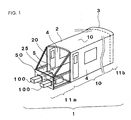
- FIGS. 1 to 4 A first embodiment in the case where the present invention is applied to a railway vehicle body structure when a transportation machine is a railway vehicle will be described with reference to FIGS. 1 to 4.
- a railway vehicle body structure 1 is constructed by a roof body structure 2 which forms a roof, end body structures 3 which form surfaces for closing both ends with respect to a vehicle body longitudinal direction, side body structures 4 which form left and right surfaces with respect to the vehicle body longitudinal direction, and an underframe 5 which forms a floor surface.
- the underframe 5 has high rigidity against a compression load in the longitudinal direction. Windows and openings for entrance/exit are formed in the side body structure 4.
- the railway vehicle body structure 1 having such a basic structure has a survival zone 10 which protects the lives of passengers and crews at the time of collision and a crushable zone 11 which absorbs energy occurring at the time of collision.
- the crushable zones 11 are placed at both end portions in the longitudinal direction of the vehicle, and are disposed so as to sandwich the survival zone 10 in the longitudinal direction of the vehicle.
- the structure is explained by using the vehicle having the driving cab 25, but in the vehicle without having the driving cab 25, the relative disposition of the crushable zone 11 and the survival zone 10 does not change.
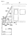
- a flying object barrier plate 50 in a planar shape with its in-plane orientation being in the direction orthogonal to the traveling direction is disposed at the end portion in the traveling direction, of the driving cab 25.
- two energy absorbing members 100 and 100 are disposed to penetrate through the flying object barrier plate 50 and to be spaced in a vehicle width direction.
- the main members which construct the crushable zone 11 are the flying object barrier plate 50, a beam member 60 and the energy absorbing members 100 and 100.
- Each of the energy absorbing members 100 is firmly connected to the survival zone 10, and is disposed to extend outward of the vehicle body along a rail direction (vehicle body longitudinal direction).
- the energy absorbing members 100 and 100 are at both end sides in the vehicle body width direction.
- the flying object barrier plate 50 is firmly connected to a vertical pillar 20 at an end portion of the survival zone 10 by the beam member 60.
- the beam member 60 includes a horizontal beam part 60a at a floor side and a horizontal beam part 60b parallel with the horizontal beam part 60a and disposed at an intermediate height, root sides of the horizontal beam parts 60a and 60b are firmly connected at the opening 25 of the survival zone 10, and tip end portions are connected to the flying object barrier plate 50. Connecting portions of the horizontal beam part 60b and the flying object barrier plate 50 and an upper end of the opening 25 of the survival zone 10 are connected by an inclined beam part 60c of the beam member 60.
- the energy absorbing member 100 is disposed to pass through a window 40, which is formed in the flying object barrier plate 50, from the body structure. Connection of the energy absorbing member 100 and the flying object barrier plate 50 is carried out to such an extent that does not restrain the behavior (collapse) when the energy absorbing member 100 deforms and absorbs energy.
- the above described collapse means to break gradually in the axial direction of the energy absorbing member 100 to be small in the bellow shape without entirely buckling.
- the above described "carried out” includes being not connected.
- the energy absorbing member 100 is constructed by disposing two body structures 100a and 100b differing in outer shape by connecting them in the vehicle body longitudinal direction. Namely, the outer shape of the energy absorbing member 100a disposed at the foremost end portion is small as compared with the energy absorbing member 100b which is placed adjacently to it at the body structure side.
- the energy absorbing member 100b is connected to the survival zone 10 via a connecting member 80.
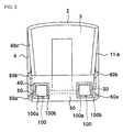
- FIG. 3 shows the view of the crushable zone 11a in which the driving cab is disposed seen from the end portion in the vehicle longitudinal direction.
- the energy absorbing members 100 and 100 penetrate through the flying object barrier plate 50 to project, seal members 30 are coated therebetween to inhibit entry of water from gaps.
- the seal member 30 has such strength as not to restrain the action when the energy absorbing member 100 deforms and absorbs energy at the time of collision.
- FIG. 4 shows the above first embodiment by comparing it with the conventional embodiment.
- a conventional embodiment 1 shown in (a) an energy absorbing member 91 is fitted to an outer side of the flying object barrier plate 50.
- an energy absorbing member 92 is placed between the flying obj ect barrier plate 50 and the survival zone.
- an energy absorbingmember 100 is fitted at the survival zone to penetrate through the flying obj ect barrier plate 50 and to project along the longitudinal direction of the vehicle.
- a state 1 in (a) shows the state before collision.
- a state 2 in (b) shows the state immediately after the collision begins. It is the energy absorbing member 100a existing at the head that starts contact at first as the vehicle body structure.
- the seal member 30 exists between the energy absorbing member 100a at the tip end side and the flying object barrier plate 50. At this time, the sectional area of the energy absorbing member 100a at the tip end side is small as compared with the sectional area of the energy absorbing member 100b at the root side, and therefore, the energy absorbing member 100a at the tip end side starts local deformation.
- a state 3 in (c) shows the state in which the collision further proceeds from the state 2.
- the seal member 30 which connects the flying object barrier plate 50 and the energy absorbing member 100a breaks.
- the direct load caused by collision does not act on the flying object barrier plate 50 at all, and the load caused by the collision acts on only the energy absorbing member 100. Therefore, deformation of the energy absorbing member 100a proceeds, and the energy absorbing member 100a deforms until there is no room for deformation. Thereafter, the energy absorbing member 100b starts deformation.
- a state 4 in (d) shows the state in which deformation advances until there is no room for deformation any more.
- a crashed remnant amount L3 of the energy absorbing member 100 is long as compared with L2, and therefore, even after deformation of the energy absorbing member 100 is finished, the tip end of the energy absorbing member 100 projects from the flying object barrier plate 50, and the flying object barrier plate 50 can avoid being deformed by the obstacle which collides with the energy absorbing member 100.
- Deformation occurs to only the energy absorbing member 100 so that both of the energy absorbing member 100a projecting from the flying object barrier plate 50 and the energy absorbing member 100b disposed in the space of the driving cab 25 deform as above, and therefore, the space of the driving cab 25 where a crew is on board is left uncrushed. Since the energy absorbing member 100 and the flying object barrier plate 50 are connected by the seal member 30, vibration during vehicle operation is reduced and at the same time, entire buckling can be prevented, in terms of the energy absorbing member 100. Therefore, the energy absorbing member 100 buckles to be small in the bellow shape, and can absorb a large load.
- the cover which covers the end body structure 3, and the energy absorbing member 100, at the front side of the end body structure 3.
- This cover is an apparent cover.
- the cover which is constructed by the flying object barrier plate 50, the members 60a, 60b and 60c can be the to be a reinforcement cover.
- a second embodiment in the case where the present invention is applied to a railway vehicle body structure will be described with reference to FIG. 6.
- the structures of the flying object barrier plate 50 and the beam member 60 are the same as the caseofthefirstembodiment.
- an energy absorbing member 200 which differs from that in the first embodiment will be described.
- the energy absorbing member 200 projecting from the flying object barrier plate 50 is constructed as two upper and lower units. In the portions constructed into the two upper and lower units, energy absorbing member portions 200c and 200d are disposed on an upper unit side, and energy absorbing member portions 200e and 200f are disposed at the lower unit side.
- the energy absorbing member portions 200c and 200d are connected side by side in the vehicle body longitudinaldirection.
- the energy absorbing member portions 200e and 200f are also connected side by side in the vehicle body longitudinal direction.
- the energy absorbing member portions 200d and 200f are both connected to an energy absorbing member 200g.
- the energy absorbing member 200g is connected to an energy absorbing member 200h, and the energy absorbing member 200h is firmly connected to the survival zone 10 via a connecting member 80.
- a distance to the tip end of the flying object barrier plate 50 is L10
- a distance to the tip end of the energy absorbing member portion 200e from the survival zone 10 is L11
- a distance to the tip end of the energy absorbing member portion 200c is L12.
- L10 ⁇ L11 ⁇ L12 is satisfied.
- the distance from the end portion of the survival zone 10, which is the nearest to the crushable structure, when the energy absorbing member finishes deformation is L120 for the energy absorbing member portion 200c, and is L110 for the energy absorbing member 200d (L110, L120 not shown). In this case, L10 ⁇ L110 ⁇ L120 is satisfied.
- the energy absorbing member portion 200c on the upper unit side which is at the longest distance from the end portion of the survival zone 10 which is the nearest to the crushable structure, starts deformation first.
- the energy absorbing member portion 200e on the lower unit side starts deformation. Since such a deformation mode is established, the same effect as described in the first embodiment can be obtained and at the same time, the peak load occurring when collapse starts can be reduced. Namely, since the timings in which the energy absorbing member portion 200c on the upper unit side and the energy absorbing member portion 200e on the lower unit side start deformation differ, and thereby, the timings in which the peak loads occur differ, the peak load as a total is reduced.
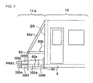
- a third embodiment in the case where the present invention is applied to a railway vehicle body structure will be described in accordance with FIG. 7.
- the structures of the flying object barrier plate 50 and the beam member 60 are the same as those in the second embodiment.
- reference numbers and characters of the 300-level are used with respect to the energy absorbing member, but as compared with the second embodiment, no difference exists except for the difference in the disposition height of the energy absorbing members, and therefore, the explanation of the other respects will be omitted.
- the energy absorbing member portions 300c and 300d disposed on the upper unit side are disposed at the position higher than the floor surface height, and the energy absorbing member portions 300e and 300f disposed on the lower unit side are disposed at the position lower than the floor surface.
- a fourth embodiment in the case where the present invention is applied to the railway vehicle body structure will be described with reference to FIG. 8.
- the structures of the flying object barrier plate 50 and the beam member 60 are the same as those in the first embodiment.
- a beam member 460 which differs from that in the first embodiment will be described.
- beam members 460a, 460b and 460c exist in the beam member 460 which connects the flying object barrier plate 50 and the survival zone.
- the connecting position in the height direction of these beam members 460 and the survival zone 10 does not exist at the intermediate height at which an entrance/exit that is an opening 400 provided at an area of the survival zone 10, which is the nearest to the crushable zone 11a.
Landscapes
- Engineering & Computer Science (AREA)
- Mechanical Engineering (AREA)
- Life Sciences & Earth Sciences (AREA)
- Wood Science & Technology (AREA)
- Transportation (AREA)
- Vibration Dampers (AREA)
- Refuge Islands, Traffic Blockers, Or Guard Fence (AREA)
- Aiming, Guidance, Guns With A Light Source, Armor, Camouflage, And Targets (AREA)
Applications Claiming Priority (1)
| Application Number | Priority Date | Filing Date | Title |
|---|---|---|---|
| JP2006131260A JP4712604B2 (ja) | 2006-05-10 | 2006-05-10 | 輸送機器 |
Publications (3)
| Publication Number | Publication Date |
|---|---|
| EP1854694A2 true EP1854694A2 (de) | 2007-11-14 |
| EP1854694A3 EP1854694A3 (de) | 2008-03-12 |
| EP1854694B1 EP1854694B1 (de) | 2012-05-23 |
Family
ID=38212241
Family Applications (1)
| Application Number | Title | Priority Date | Filing Date |
|---|---|---|---|
| EP06256332A Not-in-force EP1854694B1 (de) | 2006-05-10 | 2006-12-13 | Schienenfahrzeug mit Energieverzehreinrichtung |
Country Status (5)
| Country | Link |
|---|---|
| US (1) | US20070283843A1 (de) |
| EP (1) | EP1854694B1 (de) |
| JP (1) | JP4712604B2 (de) |
| KR (1) | KR100836089B1 (de) |
| CN (1) | CN100457520C (de) |
Cited By (6)
| Publication number | Priority date | Publication date | Assignee | Title |
|---|---|---|---|---|
| CN103661437A (zh) * | 2014-01-02 | 2014-03-26 | 南车株洲电力机车有限公司 | 一种城轨司机室结构 |
| WO2014195177A1 (de) * | 2013-06-04 | 2014-12-11 | Siemens Ag Österreich | Schienenfahrzeug mit verformungszone |
| EP2641803A4 (de) * | 2010-11-19 | 2017-06-21 | Kawasaki Jukogyo Kabushiki Kaisha | Aufprallenergieabsorbierender körper für schienenfahrzeuge |
| EP3181425A1 (de) * | 2015-12-18 | 2017-06-21 | Hitachi, Ltd. | Mit aufprallenergieabsorptionsstruktur ausgerüstetes schienenfahrzeug |
| CN109094602A (zh) * | 2018-07-27 | 2018-12-28 | 中车唐山机车车辆有限公司 | 吸能梁、轨道车辆的司机室底架结构及轨道车辆 |
| AT16474U1 (de) * | 2018-04-27 | 2019-10-15 | Bombardier Transp Gmbh | Crashkonzept Stadt-Regio-Fahrzeug |
Families Citing this family (25)
| Publication number | Priority date | Publication date | Assignee | Title |
|---|---|---|---|---|
| JP5179053B2 (ja) * | 2006-05-10 | 2013-04-10 | 株式会社日立製作所 | 衝突エネルギー吸収装置及びそれを備えた軌条車両 |
| JP5092323B2 (ja) * | 2006-09-08 | 2012-12-05 | 株式会社日立製作所 | 軌条車両 |
| KR200449788Y1 (ko) * | 2008-08-07 | 2010-08-10 | 현대로템 주식회사 | 철도 차량용 타오름 방지 장치 부착 브래킷 |
| JP5145186B2 (ja) | 2008-09-30 | 2013-02-13 | 株式会社日立製作所 | 衝突緩和装置を備えた軌条車両 |
| JP5020988B2 (ja) * | 2009-03-04 | 2012-09-05 | 近畿車輌株式会社 | 衝撃吸収装置及び鉄道車両 |
| JP4852624B2 (ja) | 2009-03-31 | 2012-01-11 | 株式会社日立製作所 | 衝突緩和装置を備えた軌条車輌 |
| US9248846B2 (en) * | 2011-12-02 | 2016-02-02 | Nippon Sharyo, Ltd. | Rolling stock |
| JP5758044B2 (ja) * | 2012-02-21 | 2015-08-05 | 日本車輌製造株式会社 | 鉄道車両 |
| GB2567736B (en) * | 2012-04-25 | 2019-08-14 | Hitachi Ltd | Railroad vehicle body structure having shock absorbing structure |
| RU2528529C1 (ru) * | 2013-04-03 | 2014-09-20 | Открытое акционерное общество "МЕТРОВАГОНМАШ" | Рельсовое транспортное средство (варианты) и устройство для защиты при аварийном столкновении |
| JP6220593B2 (ja) * | 2013-07-31 | 2017-10-25 | 日本車輌製造株式会社 | 鉄道車両 |
| JP6393458B2 (ja) | 2013-08-01 | 2018-09-19 | 川崎重工業株式会社 | 鉄道車両の先頭構造 |
| CN103625500B (zh) * | 2013-10-10 | 2016-09-07 | 中车青岛四方机车车辆股份有限公司 | 轨道车辆底架端部防撞结构 |
| JP6325127B2 (ja) * | 2014-10-28 | 2018-05-23 | 株式会社日立製作所 | 衝撃吸収装置を備えた軌条車両 |
| JP6698283B2 (ja) | 2015-06-03 | 2020-05-27 | 川崎重工業株式会社 | 鉄道車両の車体 |
| JP6603508B2 (ja) * | 2015-08-04 | 2019-11-06 | 川崎重工業株式会社 | 鉄道車両の衝突エネルギー吸収装置 |
| CN106240587B (zh) * | 2016-08-30 | 2018-12-14 | 中车株洲电力机车有限公司 | 一种轨道车辆车头结构 |
| CN106347387B (zh) * | 2016-10-09 | 2019-02-26 | 中车株洲电力机车有限公司 | 一种轨道车辆头车结构 |
| CN107914728B (zh) * | 2017-11-14 | 2019-10-01 | 中车长春轨道客车股份有限公司 | 地铁车辆的前端吸能装置 |
| JP6960833B2 (ja) * | 2017-11-27 | 2021-11-05 | 日本車輌製造株式会社 | 鉄道車両 |
| RU195045U1 (ru) * | 2019-01-21 | 2020-01-14 | ФЕДЕРАЛЬНОЕ ГОСУДАРСТВЕННОЕ БЮДЖЕТНОЕ ОБРАЗОВАТЕЛЬНОЕ УЧРЕЖДЕНИЕ ВЫСШЕГО ОБРАЗОВАНИЯ "Брянский государственный технический университет" | Рельсовое транспортное средство, имеющее кабину машиниста, обеспеченную энергопоглощающей конструкцией, выполненной с возможностью воспринимать столкновение, происходящее выше рамы транспортного средства |
| EP3929055A1 (de) * | 2020-06-22 | 2021-12-29 | Stadler Rail AG | Schienenfahrzeugwagen zum transport von passagieren, schienenfahrzeug mit einem schienenfahrzeugwagen und verfahren zur bildung eines übergangs zwischen schienenfahrzeugwagen |
| CN115320660B (zh) * | 2022-09-15 | 2023-10-31 | 中车青岛四方机车车辆股份有限公司 | 一种整体式吸能结构及轨道车辆 |
| CN115447630B (zh) * | 2022-10-21 | 2023-10-24 | 中车青岛四方机车车辆股份有限公司 | 一种端部吸能结构及轨道车辆 |
| JP7594704B1 (ja) | 2024-03-25 | 2024-12-04 | 日本車輌製造株式会社 | 鉄道車両 |
Citations (1)
| Publication number | Priority date | Publication date | Assignee | Title |
|---|---|---|---|---|
| EP1215098A1 (de) | 2000-12-18 | 2002-06-19 | Alstom | Schienenfahrzeug mit einer Fahrerkabine mit einer Struktur zur Energieaufnahme während einer Kollision oberhalb des Fahrzeugrahmens |
Family Cites Families (33)
| Publication number | Priority date | Publication date | Assignee | Title |
|---|---|---|---|---|
| GB1419698A (de) * | 1972-04-19 | 1976-01-07 | ||
| JPS5350963Y2 (de) * | 1974-02-06 | 1978-12-06 | ||
| FR2712950B1 (fr) * | 1993-11-25 | 1995-12-29 | Gec Alsthom Transport Sa | Dispositifs et procédé d'amortissement de choc, ossature et véhicule comportant de tels dispositifs d'amortissement de choc. |
| JPH08159196A (ja) * | 1994-12-05 | 1996-06-18 | Kobe Steel Ltd | エネルギー吸収部材 |
| DE19609995B4 (de) * | 1996-03-14 | 2005-04-21 | Dwa Deutsche Waggonbau Gmbh | Stirnwand für Leichtbau-Schienenfahrzeuge, insbesondere Führerstand-Stirnwand für Nahverkehrs-Schienenfahrzeuge |
| FR2747633B1 (fr) * | 1996-04-19 | 2003-01-31 | Alstom Ddf | Vehicule ferroviaire a cabine de conduite comportant une structure absorbeuse d'energie a deformation progressive |
| US6158356A (en) * | 1997-02-10 | 2000-12-12 | Gec Alsthom Transport Sa | Energy absorber device having a parallelepiped shape for absorbing impacts to a vehicle |
| FR2759338B1 (fr) * | 1997-02-10 | 1999-04-02 | Gec Alsthom Transport Sa | Dispositif d'absorption d'energie et vehicule, notamment ferroviaire, comportant un tel dispositif d'absorption |
| DE19720329C1 (de) * | 1997-05-15 | 1998-11-05 | Abb Daimler Benz Transp | Schienenfahrzeug mit Stoßverzehrelementeinrichtung |
| WO1999038751A1 (de) * | 1998-01-28 | 1999-08-05 | Siemens Krauss-Maffei Lokomotiven Gmbh | Aufprallschutzvorrichtung für schienenfahrzeuge |
| US6196135B1 (en) * | 1998-04-17 | 2001-03-06 | Kinki Sharyo Co., Ltd. | Shock absorbing underframe structure for railroad car |
| US6474489B2 (en) * | 1999-03-12 | 2002-11-05 | Thomas S. Payne | Collision attenuator |
| US6845874B2 (en) * | 1999-03-12 | 2005-01-25 | Thomas S. Payne | Collision attenuating system |
| AT408874B (de) * | 2000-02-18 | 2002-03-25 | Siemens Sgp Verkehrstech Gmbh | Deformationselement für ein schienenfahrzeug |
| FR2811624B1 (fr) * | 2000-07-12 | 2002-12-06 | Alstom | Dispositif d'echappement d'un element gonflable et dispositif de protection d'un vehicule contre le choc equipe d'un tel dispositif d'echappement |
| DE10055876A1 (de) * | 2000-11-03 | 2002-05-16 | Daimler Chrysler Ag | Stossenergie-Verzehrvorrichtung für Fahrzeuge |
| JP3512753B2 (ja) * | 2001-04-20 | 2004-03-31 | 川崎重工業株式会社 | 鉄道車両の衝突エネルギ吸収構造 |
| DE10126483A1 (de) * | 2001-05-31 | 2002-12-05 | Scharfenbergkupplung Gmbh & Co | Energieverzehreinrichtung für die Stirnseite von Schienenfahrzeugen |
| JP2003054442A (ja) * | 2001-08-16 | 2003-02-26 | Nippon Light Metal Co Ltd | 衝撃吸収体 |
| JP2003095097A (ja) * | 2001-09-25 | 2003-04-03 | Hitachi Ltd | 軌条車両 |
| JP3455205B2 (ja) * | 2002-02-18 | 2003-10-14 | 川崎重工業株式会社 | 車両間にエネルギー吸収構造を備えた列車編成 |
| FR2840274B1 (fr) * | 2002-05-31 | 2004-07-23 | Alstom | Dispositif contre l'intrusion d'une vitre dans une cabine de vehicule ferroviaire lors d'un choc |
| JP3848227B2 (ja) * | 2002-09-02 | 2006-11-22 | 株式会社日立製作所 | 軌条車両 |
| DE10254440A1 (de) * | 2002-11-21 | 2004-06-09 | Siemens Ag | Schienenfahrzeug, insbesondere Leichttriebwagen |
| JP2004268694A (ja) | 2003-03-06 | 2004-09-30 | Hitachi Ltd | 軌条車両 |
| WO2005028275A1 (en) * | 2003-09-19 | 2005-03-31 | Siemens Transportation Systems, Inc. | Integrated impact protecting system |
| DE10355640B3 (de) * | 2003-11-28 | 2004-11-04 | Voith Turbo Scharfenberg Gmbh & Co. Kg | Mittelpufferkupplung für Schienenfahrzeuge |
| ES2261859T3 (es) * | 2003-12-05 | 2006-11-16 | VOITH TURBO SCHARFENBERG GMBH & CO. KG | Enganche central de acoplamiento con dispositivo centralizador. |
| KR100583271B1 (ko) * | 2004-06-23 | 2006-05-25 | 한국철도기술연구원 | 고속전철의 전두부 충격 흡수구조 |
| ATE371561T1 (de) * | 2005-05-06 | 2007-09-15 | Voith Turbo Scharfenberg Gmbh | Trennbare mittenstellungskupplung |
| JP3848355B2 (ja) | 2005-09-08 | 2006-11-22 | 株式会社日立製作所 | 軌条車両 |
| US7536958B2 (en) * | 2006-05-09 | 2009-05-26 | Raul V. Bravo & Associates, Inc. | Passenger rail car |
| JP4943905B2 (ja) * | 2006-05-10 | 2012-05-30 | 株式会社日立製作所 | 衝突エネルギー吸収装置及びそれを備えた軌条車両 |
-
2006
- 2006-05-10 JP JP2006131260A patent/JP4712604B2/ja not_active Expired - Fee Related
- 2006-12-04 CN CNB2006101637347A patent/CN100457520C/zh not_active Expired - Fee Related
- 2006-12-07 KR KR1020060123640A patent/KR100836089B1/ko not_active Expired - Fee Related
- 2006-12-13 EP EP06256332A patent/EP1854694B1/de not_active Not-in-force
- 2006-12-14 US US11/638,495 patent/US20070283843A1/en not_active Abandoned
Patent Citations (1)
| Publication number | Priority date | Publication date | Assignee | Title |
|---|---|---|---|---|
| EP1215098A1 (de) | 2000-12-18 | 2002-06-19 | Alstom | Schienenfahrzeug mit einer Fahrerkabine mit einer Struktur zur Energieaufnahme während einer Kollision oberhalb des Fahrzeugrahmens |
Cited By (12)
| Publication number | Priority date | Publication date | Assignee | Title |
|---|---|---|---|---|
| EP2641803A4 (de) * | 2010-11-19 | 2017-06-21 | Kawasaki Jukogyo Kabushiki Kaisha | Aufprallenergieabsorbierender körper für schienenfahrzeuge |
| WO2014195177A1 (de) * | 2013-06-04 | 2014-12-11 | Siemens Ag Österreich | Schienenfahrzeug mit verformungszone |
| AT514375A1 (de) * | 2013-06-04 | 2014-12-15 | Siemens Ag Oesterreich | Schienenfahrzeug mit Verformungszone |
| AU2014277110B2 (en) * | 2013-06-04 | 2016-09-08 | Siemens Mobility Austria Gmbh | Rail vehicle with deformation zone |
| US9988061B2 (en) | 2013-06-04 | 2018-06-05 | Siemens Ag Österreich | Rail vehicle with a deformation zone |
| RU2657600C2 (ru) * | 2013-06-04 | 2018-06-14 | Сименс Аг Эстеррайх | Рельсовое транспортное средство с деформационной зоной |
| CN103661437A (zh) * | 2014-01-02 | 2014-03-26 | 南车株洲电力机车有限公司 | 一种城轨司机室结构 |
| CN103661437B (zh) * | 2014-01-02 | 2016-06-08 | 南车株洲电力机车有限公司 | 一种城轨司机室结构 |
| EP3181425A1 (de) * | 2015-12-18 | 2017-06-21 | Hitachi, Ltd. | Mit aufprallenergieabsorptionsstruktur ausgerüstetes schienenfahrzeug |
| AT16474U1 (de) * | 2018-04-27 | 2019-10-15 | Bombardier Transp Gmbh | Crashkonzept Stadt-Regio-Fahrzeug |
| CN109094602A (zh) * | 2018-07-27 | 2018-12-28 | 中车唐山机车车辆有限公司 | 吸能梁、轨道车辆的司机室底架结构及轨道车辆 |
| CN109094602B (zh) * | 2018-07-27 | 2020-04-28 | 中车唐山机车车辆有限公司 | 吸能梁、轨道车辆的司机室底架结构及轨道车辆 |
Also Published As
| Publication number | Publication date |
|---|---|
| JP4712604B2 (ja) | 2011-06-29 |
| US20070283843A1 (en) | 2007-12-13 |
| KR100836089B1 (ko) | 2008-06-09 |
| KR20070109782A (ko) | 2007-11-15 |
| CN101070073A (zh) | 2007-11-14 |
| EP1854694B1 (de) | 2012-05-23 |
| CN100457520C (zh) | 2009-02-04 |
| EP1854694A3 (de) | 2008-03-12 |
| JP2007302081A (ja) | 2007-11-22 |
Similar Documents
| Publication | Publication Date | Title |
|---|---|---|
| EP1854694B1 (de) | Schienenfahrzeug mit Energieverzehreinrichtung | |
| RU2231462C2 (ru) | Рельсовое транспортное средство, имеющее кабину машиниста, обеспеченную энергопоглощающей конструкцией, выполненной с возможностью воспринимать столкновение, происходящее выше рамы транспортного средства | |
| AU2009290832B2 (en) | Vehicle front-end for mounting to the front face of a track-bound vehicle, in particular a rail vehicle | |
| CN101138981B (zh) | 轨道车辆 | |
| JP4982611B2 (ja) | 鉄道車両 | |
| CN102741106B (zh) | 用于轨道车辆的碰撞模块及相应的轨道车辆 | |
| KR20040019824A (ko) | 레일차량 | |
| GB1583852A (en) | Side collision protection system for motor vehicles | |
| JP5752277B2 (ja) | 鉄道車両 | |
| CN101070071A (zh) | 碰撞能量吸收装置及具备该装置的轨道车辆 | |
| CN113165697B (zh) | 用于汽车车身的前舱结构总成 | |
| CA2910968A1 (en) | Rail vehicle with deformation zone | |
| GB2411630A (en) | Vehicle cabin frame with yieldable regions | |
| JP5923252B2 (ja) | 鉄道車両の先頭衝撃吸収構造 | |
| CN100522714C (zh) | 一种具备碰撞能量吸收装置的轨道车辆 | |
| JP6017544B2 (ja) | 衝撃吸収構造を備える鉄道車両構体 | |
| JP2000264203A (ja) | 鉄道車両における衝撃吸収構造及び衝撃吸収方法 | |
| JP2009262839A (ja) | 衝撃吸収構造 | |
| RU2253582C2 (ru) | Кузов железнодорожного транспортного средства | |
| JP7403609B1 (ja) | 鉄道車両 | |
| JP7594704B1 (ja) | 鉄道車両 | |
| EP3216669B1 (de) | Schienenfahrzeug mit stossabsorbierender vorrichtung | |
| US6360672B1 (en) | Locomotive with operator cabin rear impact protection | |
| US7461889B1 (en) | Collision safety structure | |
| JP2013028292A (ja) | 鉄道車両の先頭衝撃吸収構造 |
Legal Events
| Date | Code | Title | Description |
|---|---|---|---|
| PUAI | Public reference made under article 153(3) epc to a published international application that has entered the european phase |
Free format text: ORIGINAL CODE: 0009012 |
|
| 17P | Request for examination filed |
Effective date: 20061227 |
|
| AK | Designated contracting states |
Kind code of ref document: A2 Designated state(s): AT BE BG CH CY CZ DE DK EE ES FI FR GB GR HU IE IS IT LI LT LU LV MC NL PL PT RO SE SI SK TR |
|
| AX | Request for extension of the european patent |
Extension state: AL BA HR MK RS |
|
| PUAL | Search report despatched |
Free format text: ORIGINAL CODE: 0009013 |
|
| AK | Designated contracting states |
Kind code of ref document: A3 Designated state(s): AT BE BG CH CY CZ DE DK EE ES FI FR GB GR HU IE IS IT LI LT LU LV MC NL PL PT RO SE SI SK TR |
|
| AX | Request for extension of the european patent |
Extension state: AL BA HR MK RS |
|
| 17Q | First examination report despatched |
Effective date: 20080626 |
|
| AKX | Designation fees paid |
Designated state(s): AT BE BG CH CY CZ DE DK EE ES FI FR GB GR HU IE IS IT LI LT LU LV MC NL PL PT RO SE SI SK TR |
|
| GRAP | Despatch of communication of intention to grant a patent |
Free format text: ORIGINAL CODE: EPIDOSNIGR1 |
|
| RAP1 | Party data changed (applicant data changed or rights of an application transferred) |
Owner name: HITACHI, LTD. |
|
| GRAS | Grant fee paid |
Free format text: ORIGINAL CODE: EPIDOSNIGR3 |
|
| GRAA | (expected) grant |
Free format text: ORIGINAL CODE: 0009210 |
|
| AK | Designated contracting states |
Kind code of ref document: B1 Designated state(s): AT BE BG CH CY CZ DE DK EE ES FI FR GB GR HU IE IS IT LI LT LU LV MC NL PL PT RO SE SI SK TR |
|
| REG | Reference to a national code |
Ref country code: GB Ref legal event code: FG4D |
|
| REG | Reference to a national code |
Ref country code: CH Ref legal event code: EP Ref country code: CH Ref legal event code: NV Representative=s name: TROESCH SCHEIDEGGER WERNER AG |
|
| REG | Reference to a national code |
Ref country code: AT Ref legal event code: REF Ref document number: 558937 Country of ref document: AT Kind code of ref document: T Effective date: 20120615 |
|
| REG | Reference to a national code |
Ref country code: IE Ref legal event code: FG4D |
|
| REG | Reference to a national code |
Ref country code: DE Ref legal event code: R096 Ref document number: 602006029632 Country of ref document: DE Effective date: 20120719 |
|
| REG | Reference to a national code |
Ref country code: NL Ref legal event code: VDEP Effective date: 20120523 |
|
| REG | Reference to a national code |
Ref country code: LT Ref legal event code: MG4D Effective date: 20120523 |
|
| PG25 | Lapsed in a contracting state [announced via postgrant information from national office to epo] |
Ref country code: CY Free format text: LAPSE BECAUSE OF FAILURE TO SUBMIT A TRANSLATION OF THE DESCRIPTION OR TO PAY THE FEE WITHIN THE PRESCRIBED TIME-LIMIT Effective date: 20120523 Ref country code: IS Free format text: LAPSE BECAUSE OF FAILURE TO SUBMIT A TRANSLATION OF THE DESCRIPTION OR TO PAY THE FEE WITHIN THE PRESCRIBED TIME-LIMIT Effective date: 20120923 Ref country code: FI Free format text: LAPSE BECAUSE OF FAILURE TO SUBMIT A TRANSLATION OF THE DESCRIPTION OR TO PAY THE FEE WITHIN THE PRESCRIBED TIME-LIMIT Effective date: 20120523 Ref country code: LT Free format text: LAPSE BECAUSE OF FAILURE TO SUBMIT A TRANSLATION OF THE DESCRIPTION OR TO PAY THE FEE WITHIN THE PRESCRIBED TIME-LIMIT Effective date: 20120523 Ref country code: SE Free format text: LAPSE BECAUSE OF FAILURE TO SUBMIT A TRANSLATION OF THE DESCRIPTION OR TO PAY THE FEE WITHIN THE PRESCRIBED TIME-LIMIT Effective date: 20120523 |
|
| REG | Reference to a national code |
Ref country code: AT Ref legal event code: MK05 Ref document number: 558937 Country of ref document: AT Kind code of ref document: T Effective date: 20120523 |
|
| PG25 | Lapsed in a contracting state [announced via postgrant information from national office to epo] |
Ref country code: GR Free format text: LAPSE BECAUSE OF FAILURE TO SUBMIT A TRANSLATION OF THE DESCRIPTION OR TO PAY THE FEE WITHIN THE PRESCRIBED TIME-LIMIT Effective date: 20120824 Ref country code: SI Free format text: LAPSE BECAUSE OF FAILURE TO SUBMIT A TRANSLATION OF THE DESCRIPTION OR TO PAY THE FEE WITHIN THE PRESCRIBED TIME-LIMIT Effective date: 20120523 Ref country code: LV Free format text: LAPSE BECAUSE OF FAILURE TO SUBMIT A TRANSLATION OF THE DESCRIPTION OR TO PAY THE FEE WITHIN THE PRESCRIBED TIME-LIMIT Effective date: 20120523 Ref country code: PT Free format text: LAPSE BECAUSE OF FAILURE TO SUBMIT A TRANSLATION OF THE DESCRIPTION OR TO PAY THE FEE WITHIN THE PRESCRIBED TIME-LIMIT Effective date: 20120924 |
|
| PG25 | Lapsed in a contracting state [announced via postgrant information from national office to epo] |
Ref country code: BE Free format text: LAPSE BECAUSE OF FAILURE TO SUBMIT A TRANSLATION OF THE DESCRIPTION OR TO PAY THE FEE WITHIN THE PRESCRIBED TIME-LIMIT Effective date: 20120523 |
|
| PG25 | Lapsed in a contracting state [announced via postgrant information from national office to epo] |
Ref country code: SK Free format text: LAPSE BECAUSE OF FAILURE TO SUBMIT A TRANSLATION OF THE DESCRIPTION OR TO PAY THE FEE WITHIN THE PRESCRIBED TIME-LIMIT Effective date: 20120523 Ref country code: RO Free format text: LAPSE BECAUSE OF FAILURE TO SUBMIT A TRANSLATION OF THE DESCRIPTION OR TO PAY THE FEE WITHIN THE PRESCRIBED TIME-LIMIT Effective date: 20120523 Ref country code: DK Free format text: LAPSE BECAUSE OF FAILURE TO SUBMIT A TRANSLATION OF THE DESCRIPTION OR TO PAY THE FEE WITHIN THE PRESCRIBED TIME-LIMIT Effective date: 20120523 Ref country code: AT Free format text: LAPSE BECAUSE OF FAILURE TO SUBMIT A TRANSLATION OF THE DESCRIPTION OR TO PAY THE FEE WITHIN THE PRESCRIBED TIME-LIMIT Effective date: 20120523 Ref country code: EE Free format text: LAPSE BECAUSE OF FAILURE TO SUBMIT A TRANSLATION OF THE DESCRIPTION OR TO PAY THE FEE WITHIN THE PRESCRIBED TIME-LIMIT Effective date: 20120523 Ref country code: NL Free format text: LAPSE BECAUSE OF FAILURE TO SUBMIT A TRANSLATION OF THE DESCRIPTION OR TO PAY THE FEE WITHIN THE PRESCRIBED TIME-LIMIT Effective date: 20120523 Ref country code: CZ Free format text: LAPSE BECAUSE OF FAILURE TO SUBMIT A TRANSLATION OF THE DESCRIPTION OR TO PAY THE FEE WITHIN THE PRESCRIBED TIME-LIMIT Effective date: 20120523 |
|
| PG25 | Lapsed in a contracting state [announced via postgrant information from national office to epo] |
Ref country code: IT Free format text: LAPSE BECAUSE OF FAILURE TO SUBMIT A TRANSLATION OF THE DESCRIPTION OR TO PAY THE FEE WITHIN THE PRESCRIBED TIME-LIMIT Effective date: 20120523 Ref country code: PL Free format text: LAPSE BECAUSE OF FAILURE TO SUBMIT A TRANSLATION OF THE DESCRIPTION OR TO PAY THE FEE WITHIN THE PRESCRIBED TIME-LIMIT Effective date: 20120523 |
|
| PLBE | No opposition filed within time limit |
Free format text: ORIGINAL CODE: 0009261 |
|
| STAA | Information on the status of an ep patent application or granted ep patent |
Free format text: STATUS: NO OPPOSITION FILED WITHIN TIME LIMIT |
|
| PG25 | Lapsed in a contracting state [announced via postgrant information from national office to epo] |
Ref country code: ES Free format text: LAPSE BECAUSE OF FAILURE TO SUBMIT A TRANSLATION OF THE DESCRIPTION OR TO PAY THE FEE WITHIN THE PRESCRIBED TIME-LIMIT Effective date: 20120903 |
|
| 26N | No opposition filed |
Effective date: 20130226 |
|
| REG | Reference to a national code |
Ref country code: DE Ref legal event code: R097 Ref document number: 602006029632 Country of ref document: DE Effective date: 20130226 |
|
| PG25 | Lapsed in a contracting state [announced via postgrant information from national office to epo] |
Ref country code: MC Free format text: LAPSE BECAUSE OF NON-PAYMENT OF DUE FEES Effective date: 20121231 Ref country code: BG Free format text: LAPSE BECAUSE OF FAILURE TO SUBMIT A TRANSLATION OF THE DESCRIPTION OR TO PAY THE FEE WITHIN THE PRESCRIBED TIME-LIMIT Effective date: 20120823 |
|
| REG | Reference to a national code |
Ref country code: IE Ref legal event code: MM4A |
|
| PG25 | Lapsed in a contracting state [announced via postgrant information from national office to epo] |
Ref country code: IE Free format text: LAPSE BECAUSE OF NON-PAYMENT OF DUE FEES Effective date: 20121213 |
|
| PGFP | Annual fee paid to national office [announced via postgrant information from national office to epo] |
Ref country code: CH Payment date: 20131212 Year of fee payment: 8 |
|
| PG25 | Lapsed in a contracting state [announced via postgrant information from national office to epo] |
Ref country code: TR Free format text: LAPSE BECAUSE OF FAILURE TO SUBMIT A TRANSLATION OF THE DESCRIPTION OR TO PAY THE FEE WITHIN THE PRESCRIBED TIME-LIMIT Effective date: 20120523 |
|
| PG25 | Lapsed in a contracting state [announced via postgrant information from national office to epo] |
Ref country code: LU Free format text: LAPSE BECAUSE OF NON-PAYMENT OF DUE FEES Effective date: 20121213 |
|
| PG25 | Lapsed in a contracting state [announced via postgrant information from national office to epo] |
Ref country code: HU Free format text: LAPSE BECAUSE OF FAILURE TO SUBMIT A TRANSLATION OF THE DESCRIPTION OR TO PAY THE FEE WITHIN THE PRESCRIBED TIME-LIMIT Effective date: 20061213 |
|
| REG | Reference to a national code |
Ref country code: CH Ref legal event code: PL |
|
| PG25 | Lapsed in a contracting state [announced via postgrant information from national office to epo] |
Ref country code: LI Free format text: LAPSE BECAUSE OF NON-PAYMENT OF DUE FEES Effective date: 20141231 Ref country code: CH Free format text: LAPSE BECAUSE OF NON-PAYMENT OF DUE FEES Effective date: 20141231 |
|
| REG | Reference to a national code |
Ref country code: FR Ref legal event code: PLFP Year of fee payment: 10 |
|
| REG | Reference to a national code |
Ref country code: FR Ref legal event code: PLFP Year of fee payment: 11 |
|
| REG | Reference to a national code |
Ref country code: FR Ref legal event code: PLFP Year of fee payment: 12 |
|
| PGFP | Annual fee paid to national office [announced via postgrant information from national office to epo] |
Ref country code: DE Payment date: 20211102 Year of fee payment: 16 Ref country code: FR Payment date: 20211109 Year of fee payment: 16 |
|
| REG | Reference to a national code |
Ref country code: DE Ref legal event code: R119 Ref document number: 602006029632 Country of ref document: DE |
|
| PG25 | Lapsed in a contracting state [announced via postgrant information from national office to epo] |
Ref country code: DE Free format text: LAPSE BECAUSE OF NON-PAYMENT OF DUE FEES Effective date: 20230701 |
|
| PG25 | Lapsed in a contracting state [announced via postgrant information from national office to epo] |
Ref country code: FR Free format text: LAPSE BECAUSE OF NON-PAYMENT OF DUE FEES Effective date: 20221231 |
|
| PGFP | Annual fee paid to national office [announced via postgrant information from national office to epo] |
Ref country code: GB Payment date: 20231102 Year of fee payment: 18 |
|
| GBPC | Gb: european patent ceased through non-payment of renewal fee |
Effective date: 20241213 |
|
| PG25 | Lapsed in a contracting state [announced via postgrant information from national office to epo] |
Ref country code: GB Free format text: LAPSE BECAUSE OF NON-PAYMENT OF DUE FEES Effective date: 20241213 |