EP1854945A2 - Système de verrouillage pour une porte d'un véhicule automobile avec plusieurs éléments de verrouillage et une unité de contrôle commune - Google Patents
Système de verrouillage pour une porte d'un véhicule automobile avec plusieurs éléments de verrouillage et une unité de contrôle commune Download PDFInfo
- Publication number
- EP1854945A2 EP1854945A2 EP07007965A EP07007965A EP1854945A2 EP 1854945 A2 EP1854945 A2 EP 1854945A2 EP 07007965 A EP07007965 A EP 07007965A EP 07007965 A EP07007965 A EP 07007965A EP 1854945 A2 EP1854945 A2 EP 1854945A2
- Authority
- EP
- European Patent Office
- Prior art keywords
- control disk
- control
- locking
- locking system
- motor vehicle
- Prior art date
- Legal status (The legal status is an assumption and is not a legal conclusion. Google has not performed a legal analysis and makes no representation as to the accuracy of the status listed.)
- Granted
Links
- 230000007246 mechanism Effects 0.000 claims abstract description 46
- 230000005540 biological transmission Effects 0.000 claims abstract description 19
- 230000033001 locomotion Effects 0.000 claims description 24
- 230000002779 inactivation Effects 0.000 claims description 17
- 230000000415 inactivating effect Effects 0.000 abstract 1
- 230000009849 deactivation Effects 0.000 description 8
- 230000008878 coupling Effects 0.000 description 7
- 238000010168 coupling process Methods 0.000 description 7
- 238000005859 coupling reaction Methods 0.000 description 7
- 238000010276 construction Methods 0.000 description 5
- 230000009471 action Effects 0.000 description 4
- 230000000712 assembly Effects 0.000 description 4
- 238000000429 assembly Methods 0.000 description 4
- 230000008901 benefit Effects 0.000 description 4
- 238000013461 design Methods 0.000 description 3
- 238000011161 development Methods 0.000 description 3
- 230000018109 developmental process Effects 0.000 description 3
- 230000010354 integration Effects 0.000 description 3
- 238000000034 method Methods 0.000 description 3
- 230000008569 process Effects 0.000 description 3
- 230000002441 reversible effect Effects 0.000 description 3
- 230000004913 activation Effects 0.000 description 2
- 230000012447 hatching Effects 0.000 description 2
- 230000003993 interaction Effects 0.000 description 2
- 238000004519 manufacturing process Methods 0.000 description 2
- 230000003213 activating effect Effects 0.000 description 1
- 238000013459 approach Methods 0.000 description 1
- 230000003750 conditioning effect Effects 0.000 description 1
- 239000004020 conductor Substances 0.000 description 1
- 230000001419 dependent effect Effects 0.000 description 1
- 238000001035 drying Methods 0.000 description 1
- 230000000694 effects Effects 0.000 description 1
- 230000000977 initiatory effect Effects 0.000 description 1
- 230000009347 mechanical transmission Effects 0.000 description 1
- 238000012546 transfer Methods 0.000 description 1
Images


Classifications
-
- E—FIXED CONSTRUCTIONS
- E05—LOCKS; KEYS; WINDOW OR DOOR FITTINGS; SAFES
- E05B—LOCKS; ACCESSORIES THEREFOR; HANDCUFFS
- E05B63/00—Locks or fastenings with special structural characteristics
- E05B63/14—Arrangement of several locks or locks with several bolts, e.g. arranged one behind the other
- E05B63/143—Arrangement of several locks, e.g. in parallel or series, on one or more wings
-
- E—FIXED CONSTRUCTIONS
- E05—LOCKS; KEYS; WINDOW OR DOOR FITTINGS; SAFES
- E05B—LOCKS; ACCESSORIES THEREFOR; HANDCUFFS
- E05B77/00—Vehicle locks characterised by special functions or purposes
- E05B77/22—Functions related to actuation of locks from the passenger compartment of the vehicle
- E05B77/24—Functions related to actuation of locks from the passenger compartment of the vehicle preventing use of an inner door handle, sill button, lock knob or the like
- E05B77/26—Functions related to actuation of locks from the passenger compartment of the vehicle preventing use of an inner door handle, sill button, lock knob or the like specially adapted for child safety
-
- E—FIXED CONSTRUCTIONS
- E05—LOCKS; KEYS; WINDOW OR DOOR FITTINGS; SAFES
- E05B—LOCKS; ACCESSORIES THEREFOR; HANDCUFFS
- E05B81/00—Power-actuated vehicle locks
- E05B81/02—Power-actuated vehicle locks characterised by the type of actuators used
- E05B81/04—Electrical
- E05B81/06—Electrical using rotary motors
-
- E—FIXED CONSTRUCTIONS
- E05—LOCKS; KEYS; WINDOW OR DOOR FITTINGS; SAFES
- E05B—LOCKS; ACCESSORIES THEREFOR; HANDCUFFS
- E05B83/00—Vehicle locks specially adapted for particular types of wing or vehicle
- E05B83/36—Locks for passenger or like doors
- E05B83/40—Locks for passenger or like doors for sliding doors
-
- E—FIXED CONSTRUCTIONS
- E05—LOCKS; KEYS; WINDOW OR DOOR FITTINGS; SAFES
- E05B—LOCKS; ACCESSORIES THEREFOR; HANDCUFFS
- E05B77/00—Vehicle locks characterised by special functions or purposes
- E05B77/22—Functions related to actuation of locks from the passenger compartment of the vehicle
- E05B77/24—Functions related to actuation of locks from the passenger compartment of the vehicle preventing use of an inner door handle, sill button, lock knob or the like
- E05B77/26—Functions related to actuation of locks from the passenger compartment of the vehicle preventing use of an inner door handle, sill button, lock knob or the like specially adapted for child safety
- E05B77/265—Functions related to actuation of locks from the passenger compartment of the vehicle preventing use of an inner door handle, sill button, lock knob or the like specially adapted for child safety hand actuated, e.g. by a lever at the edge of the door
-
- E—FIXED CONSTRUCTIONS
- E05—LOCKS; KEYS; WINDOW OR DOOR FITTINGS; SAFES
- E05B—LOCKS; ACCESSORIES THEREFOR; HANDCUFFS
- E05B81/00—Power-actuated vehicle locks
- E05B81/12—Power-actuated vehicle locks characterised by the function or purpose of the powered actuators
- E05B81/14—Power-actuated vehicle locks characterised by the function or purpose of the powered actuators operating on bolt detents, e.g. for unlatching the bolt
-
- E—FIXED CONSTRUCTIONS
- E05—LOCKS; KEYS; WINDOW OR DOOR FITTINGS; SAFES
- E05B—LOCKS; ACCESSORIES THEREFOR; HANDCUFFS
- E05B81/00—Power-actuated vehicle locks
- E05B81/12—Power-actuated vehicle locks characterised by the function or purpose of the powered actuators
- E05B81/20—Power-actuated vehicle locks characterised by the function or purpose of the powered actuators for assisting final closing or for initiating opening
-
- E—FIXED CONSTRUCTIONS
- E05—LOCKS; KEYS; WINDOW OR DOOR FITTINGS; SAFES
- E05B—LOCKS; ACCESSORIES THEREFOR; HANDCUFFS
- E05B85/00—Details of vehicle locks not provided for in groups E05B77/00 - E05B83/00
- E05B85/01—Mechanical arrangements specially adapted for hands-free locking or unlocking
-
- E—FIXED CONSTRUCTIONS
- E05—LOCKS; KEYS; WINDOW OR DOOR FITTINGS; SAFES
- E05C—BOLTS OR FASTENING DEVICES FOR WINGS, SPECIALLY FOR DOORS OR WINDOWS
- E05C17/00—Devices for holding wings open; Devices for limiting opening of wings or for holding wings open by a movable member extending between frame and wing; Braking devices, stops or buffers, combined therewith
- E05C17/56—Devices for holding wings open; Devices for limiting opening of wings or for holding wings open by a movable member extending between frame and wing; Braking devices, stops or buffers, combined therewith by magnetic or electromagnetic attraction or operated by electric or electromagnetic means
-
- E—FIXED CONSTRUCTIONS
- E05—LOCKS; KEYS; WINDOW OR DOOR FITTINGS; SAFES
- E05C—BOLTS OR FASTENING DEVICES FOR WINGS, SPECIALLY FOR DOORS OR WINDOWS
- E05C17/00—Devices for holding wings open; Devices for limiting opening of wings or for holding wings open by a movable member extending between frame and wing; Braking devices, stops or buffers, combined therewith
- E05C17/60—Devices for holding wings open; Devices for limiting opening of wings or for holding wings open by a movable member extending between frame and wing; Braking devices, stops or buffers, combined therewith holding sliding wings open
Definitions
- the present invention relates to a closing system for a motor vehicle door comprising a plurality of spaced-apart positionable closing elements and a common control unit spaced from the closing elements for operation of these closing elements.
- the invention finds particular application in sliding doors of passenger cars.
- the invention is particularly concerned with the integration of a motor vehicle door locking system in a motor vehicle door or flap and / or in an outer lubrahmen the vehicle body, in which the motor vehicle door or flap is inserted. It is particularly about side doors, preferably sliding doors, rear doors, tailgates, trunk lids, roof structures and the like.
- motor vehicle doors must be provided regularly several door locks or locking units that securely fix the position of the motor vehicle door with respect to the vehicle in the closed and / or in the open state.
- Such a motor vehicle door locking system is for example from the DE 102 33 485 A1 out.
- a similar system in which additionally a locking mechanism for a window pane is centrally controlled, goes out of the DE 10 2005 019 607 A1 out.
- the known door locking systems are sometimes too complicated, so that in particular a large number of different parts to achieve only a limited functionality of the door closing system is needed.
- known systems also partially electronic adjusting means for the door locking systems are used, which can lead to higher manufacturing and operating costs in terms of the production of such a door locking system and as a result of increased susceptibility.
- the object of the present invention is to at least partially solve the problems described with reference to the prior art.
- a locking system for a motor vehicle door is to be specified, in which a control of the various closing elements is realized in a particularly simple, in particular mainly mechanical way.
- actuations of the closing elements are to be made possible.
- a closing system for a motor vehicle door comprising a plurality of spaced-apart positionable closing elements and a spaced from the closing elements common control unit for operating these closing elements
- the control unit is a multi-part control disc wherein at least a first control disk is connected to an actuating unit and a second control disk is provided, which is connected to a plurality of closing elements in each case via a transmission means, wherein the first control disk and the second control disk can be decoupled.
- the locking system it should be noted that this can be present on the one hand as a kind of kit which can be fastened to a motor vehicle door or another, in particular initially mentioned construction; However, it is also possible that the locking system is already mounted with respect to one of these structures or vehicle doors. Even if the focus here is primarily on an application on a motor vehicle door, closing systems for flaps, roof structures and the like should also be included.
- a plurality of closing elements can now be positioned or positioned at a distance from one another.
- at least three locking elements are provided, optionally, e.g. also four locking elements.
- Locking element considered in particular locking systems, which interact with another component of a motor vehicle, such as another motor vehicle door, the vehicle body, the so-called A-, B- and / or C-pillar.
- other locking systems, anchors and the like such as so-called doorstops may be included.
- closing elements are now operated by a common control unit which can be positioned or positioned at a further position of the motor vehicle door. All in detail later explained actuating actions for the closing elements, which can be initiated by a person, for example, are brought together in the control unit, starting from the control unit, the closing elements then actuated via a respective transmission means can be. In this case, at least two of the closing elements are actuated simultaneously by the control unit, in particular all closing elements designed in the manner of a door lock are included.
- a multi-part control disk is now proposed, wherein at least one first control disk is connected to the actuating units for initiating a closing element actuation.
- Another, second control disc now causes (under certain conditions) actually a simultaneous handling of the closing elements, in particular all door locks the motor vehicle door.
- the first control disk and the second control disk are decoupled. This decoupling is particularly preferably carried out mechanically.
- This coupling has in particular the consequence that a movement acting on the first control disk movement can be transmitted to the second control disk according to the state of the coupling or not.
- the first control disk and the second control disk at least partially perform a common rotation about a common control axis during the active state of the coupling, while only one rotation of the first control disk occurs in the inactive state of the coupling.
- the first control disk is connected to a first, outer, actuating unit, wherein means are provided for decoupling from the second control disk as a function of a plurality of inactivation mechanisms.
- a first, outer, actuating unit is meant in particular an outside door handle, wherein its activation can be forwarded via corresponding transmission means to the first control disk.
- the first control disk also interacts with means for decoupling from the second control disk, such as a clutch lever or the like.
- the decoupling of the first control disk from the second control disk can be carried out.
- Possible inactivation mechanisms relate to the central lock state, the in-lock state, and / or a lock cylinder lock state.
- the means for decoupling can be converted into a state such that the first control disk and the second control disk are decoupled.
- Particularly preferred is the variant in which two or three inactivation mechanisms act on the means for decoupling the first control disk.
- a third control disk is connected to an actuating unit, wherein the second control disk is arranged centrally and decoupled from the first control disk and the third control disk.
- the control disks (partially) on different outer contours (edge curves in the circumferential direction of the control discs), which are formed for driving transmission means and the like.
- the second control disk with the first or the third control disk with active coupling with moves, therefore, relative to the other two, preferably arranged on both sides of the second control disk control discs is movable.
- the third control disk can interact, for example, with a non-contact actuating unit and / or a mechanical actuating unit, which is different in particular from the first, outer, actuating unit.
- a variant of the locking system is preferred, in which a third control disk is connected to a second, inner, actuating unit, wherein means for decoupling from the second control disk are provided as a function of at least one inactivation mechanism.
- the second, inner, actuating unit is, in particular, a door inside handle of the motor vehicle door.
- the multi-part control disk is connected to a drive, wherein at least the movement of a component of a closing element is effected with the drive.
- a component of at least one closing element it is preferred that an electrically or electromotively assisted opening and / or closing of the components of a lock element is thereby initiated.
- the drive acts at least on the second control disk, which (possibly rigidly) cooperates via the transmission means with a locking part of the closing element, in particular the pawl.
- the drive directly (or possibly also via at least one control disk), the movement of another locking member, in particular the rotary latch support. If this function is to be implemented with respect to all door locks, these are to be equipped (in particular with regard to the electric motor-assisted closing) with a suitable rotary latch, which in particular has a so-called preliminary catch and a so-called main catch. It should be pointed out at this point that the aspect of the central drive for moving at least one component of a closing element (possibly for realizing a quick release) can also be used advantageously independent of the embodiment of the locking system with multi-part control disk described here.
- a locking system is also proposed in which the multi-part control disc can be brought into engagement with an actuator for at least one locking mechanism of the motor vehicle door, which fixes the motor vehicle door in an open state.
- a locking mechanism is understood in particular to be a so-called doorstop, which engages with other body components when the motor vehicle door is fully open.
- Such a locking mechanism is in particular spring biased so that it cooperates with a corresponding engagement device on the motor vehicle when the motor vehicle door has reached the fully open position.
- the multi-part control disc can act on the actuator, in particular, the spring force or closing force of the locking mechanism is overcome. In this required movement of the multi-part control disk z. B.
- the inside door handle and / or the outside door handle may be caused by the inside door handle and / or the outside door handle, advantageously no components of the other closing elements are moved, so that only a very small force to deactivate the locking mechanism must be applied on the user side.
- This can be achieved, for example, by in that the actuation of the respective pawls performs an idle stroke, in particular as a result of a position of the pawl deflected relative to the basic position (main catch) at this time of deactivation of the locking means in the open state of the door.
- control unit comprise at least the following components: a multipart control disk, a first clutch for a first actuating unit, a second clutch for a second actuating unit, a first motor in conjunction with the first clutch and a second motor in conjunction with the second Clutch.
- control unit already combines at least two clutches each of which can preferably be operated mechanically and / or electromotively assisted.
- the user always has the ability to turn the operating units (inside door handle, outside door handle) itself, but this can also be via appropriate sensors at these points and / or an electronic control unit and an identification transmitter (so-called keyless entry system) of the User be realized.
- the clutch is independently actuated mechanically or electromotively supported. This creates the opportunity to (de) activate parental controls or central locks mechanically or by radio.
- control unit for the multi-part control disk, an actuator for at least one locking mechanism and a control system.
- the control system comprises, in particular, electrical or electronic components, such as sensors, microswitches, microcontrollers, connectors, printed conductors and the like.
- the control system is used in particular for the operation of the motors, but may also have other and / or additional functions take. All the above-mentioned components are optionally attached to an outer cover on a part of the motor vehicle door to protect it against moisture and dirt or to hold each other in a defined position to each other.
- a locking system in which the transmission means moved by the control unit are connected to a locking part of the closing elements.
- the transmission levers, motors, microswitches and the like used in separate door locks are at least partially displaced into the common control unit, so that the parts expense can be reduced in the case of the several closing elements themselves.
- the locking system can advantageously also be developed in such a way that it is integrated in a sliding door of a motor vehicle, in which the closing elements are arranged in a wet area and the control unit with the components supplied with power for operating the closing elements in the dry area.
- the functions of the electrically opening door lock the electromotive assisted closing of the catch and electric motor assisted child safety devices and / or central locking in the sliding door can be realized so that the current-carrying components such as motors, tracks, sensors, etc. relatively far away from the actual Closing elements are arranged while being protected from moisture.
- This advantage is further enhanced, in particular, by the fact that only mechanical transmission means, such as, for example, linkage or construction cables, are used towards the closing elements.
- Fig. 1 shows an embodiment of a locking system 1 on a motor vehicle door 2, which is designed here in the manner of a sliding door 25.
- a sliding door 25 is regularly moved parallel to the motor vehicle 28, for example between a so-called B-pillar and a so-called C-pillar.
- the heart of the locking system 1 illustrated here is a central control unit 4 for operating a plurality of locking elements 3 positioned at a distance therefrom.
- a first closing element 3 for example a so-called secondary lock
- another closing element 3 for example, a so-called main lock
- the sliding door 25 in the lower right area a third closing element 3 (for example, in the manner of a locking mechanism or a door stopper), and in the left area is a, sometimes referred to as a front lock, further closing element 3 is arranged.
- the common control unit 4 can act on all closing elements 3 via separate transmission means 7, in particular actuate or activate and / or deactivate them.
- actuation units for example a first actuation unit 8 (eg outside door handle), a second actuation unit 9 (eg inside door handle) and / or a sensor 29 for contactless actuation of the motor vehicle door 2.
- actuation units for example a first actuation unit 8 (eg outside door handle), a second actuation unit 9 (eg inside door handle) and / or a sensor 29 for contactless actuation of the motor vehicle door 2.
- actuation units for example a first actuation unit 8 (eg outside door handle), a second actuation unit 9 (eg inside door handle) and / or a sensor 29 for contactless actuation of the motor vehicle door 2.
- actuation units for example a first actuation unit 8 (eg outside door handle), a second actuation unit 9 (eg inside door handle) and / or a sensor 29 for contactless actuation of the motor vehicle door 2.
- actuation units for example a first actuation unit 8 (eg outside door handle),
- Links in Fig. 1 is enlarged and illustrated in a detail a specific embodiment of a closing element 3 as a motor vehicle door lock.
- This locking element 3 comprises two locking parts 24, namely on the one hand a catch 30 and on the other hand a pawl 31.
- the pawl 31 locks the spring-loaded catch 30 advantageously initially in a so-called pre-rest 33 and finally in a main catch 34.
- Preferred is a variant of the locking system 1, in which the control unit 4 via its transmission means 7 acts directly on the pawl 31 or the rotary latch 30.
- a sliding door 25 can be subdivided into a wet area 26 and into a dry area 27, with regularly sealed walls for delimiting these two areas.
- the control unit 4 is positioned in the drying area 27 and connected via separate transmission means 7 to the individual closing elements 3 arranged in the wet area 26.
- FIG. 3 shows, partially in perspective, a variant for a common control unit 4, wherein a plurality of different operating and / or locking states with respect to the closing elements 3 are realized in a small space.
- various parts in FIG. 3 are marked with hatchings or patterns, whereby an interaction of these parts is to be illustrated. Below, these assemblies are again illustrated in detail and explained their mode of action.
- the multi-piece control disk Centrally in the upper part of Fig. 3, the multi-piece control disk is shown.
- This multi-part control disk comprises three control disks, which are (temporarily) rotatably positioned against each other on a common control axis 64. Recognizable in this plan view are the first control disk 5 arranged above and the second control disk 6 located therebelow.
- the third control disk 12 arranged underneath can be seen in a rear view of the control unit 4, as illustrated in FIG. 5 or FIG.
- the first control disk 5 is articulated via a transmission means 7, which is characterized by a crossed hatching.
- the active combination of the first control disk 5 with the second control disk 6 can be decoupled by a first clutch 16. Therefore, substantial inactivation mechanisms or parts having a same cooperating with this first clutch 16 have been made Hatch marked. The operation of these components will be explained in more detail with reference to FIG.
- the black marked transmission means 7 are executed here in the manner of a linkage and transmit the movement of the second control disk 6 on the closing elements to be actuated 3.
- the black marked transmission means 7 are executed here in the manner of a linkage and transmit the movement of the second control disk 6 on the closing elements to be actuated 3.
- the movement of the second control disk 6 directly three different, spaced-apart, closing elements 3 after Type of a door lock operated. This will be illustrated in detail with reference to FIG.
- the third control disk 12 interacts with the transmission means 7 shown at the top left, marked with small dots.
- the operative connection between this third control disk 12 and the second control disk 6 is, if necessary, separated via a second clutch 17, the components or levers acting on the second clutch 17 having the same, dotted, marking. This mechanism will be explained in detail with reference to FIG. 5.
- control unit 4 shown here comprises a control system 20, in particular for driving various electric motors, for detecting positions of the components illustrated here, and the like.
- components or modular assemblies can be positioned, which cooperate with the movement of the multi-part control disk.
- a drive 13 can be seen above the control system 20, which can effect the movement of a component of a closing element with the correspondingly marked transmission means 7. This process will be described in more detail with reference to FIG.
- control unit 4 comprises, as a further assembly, an actuator 14 for a locking mechanism.
- the associated motion sequences are shown in FIG. 7.
- Such a control unit 4 is advantageously modular. This means, in particular, that the assemblies comprising the drive 13 and / or the actuator 14 as well as the functions associated therewith can also be implemented independently of this control unit 4, which is specifically proposed here. The integration of these modules in the central control unit, however, brings considerable benefits.
- Fig. 4 now illustrates in detail the movements that occur in the interaction of the first control disk 5 with the first clutch 16 and the second control disk 6.
- the first control disk 5 is here connected to the so-called external operating lever 35, so that, for example, the movements on an outside door handle of the vehicle door act on the first control disk 5.
- the external operating lever 35 is thus displaced in the direction indicated by the black arrow.
- the movement transfer to the (not shown) second control disk 6 via the first clutch lever 38, which rests on the one hand on the first control disk 5 and on the other in a first guide 36 of the second control disk. 6 is stored. If the first control disk 5 rotates, this movement is transmitted via the first clutch lever 38 and the first guide 36 to the second control disk 6, so that they execute a rotation synchronously about the common control axis.
- the first clutch lever 38 In order to be transferred to an inactive state, the first clutch lever 38 is moved in the manner indicated by a white arrow, the first guide 36 toward the control axis, so that with a corresponding movement of the first control disk 5, an idle stroke takes place, because the first clutch lever 38 then moved into the first recess 37 of the first control disk 5.
- the second control disk 6 is stationary, even if the first control disk 5 rotates.
- the first inactivation mechanism 10 relates, for example, to the case that a lock cylinder located on the motor vehicle door is mechanically transferred to a locked state.
- a lock cylinder now acts on the illustrated outer locking lever 39, which is displaced in the direction of the 3-fold arrow.
- the external operating lever 39 is moved in the reverse direction (unlocking the lock cylinder), this movement is reversed, so that the operative connection between the first control disk 5 and the second control disk 6 is restored.
- a second deactivation mechanism 11 relates, for example, to a so-called internal lock.
- push buttons and / or switches or the like may be provided with which the user of the motor vehicle, starting from the interior of the motor vehicle, can deactivate the closing elements 3 or the actuating units. If he presses one of these push buttons or switches, so the inner locking lever 46 moves downwards, as shown here with a double arrow. Based on this movement, the rotary plate 41 is moved around its pivot axis, wherein the hinged to the rotary plate 41 first clutch lever 38 is guided so that the two control discs 5, 6 are separated again. This movement is reversible and is initiated by a corresponding actuation of the inner locking lever 46.
- a central locking system which may be transmitted by radio, which may form a third deactivation mechanism 21. It is particularly preferred that this inactivation mechanism 21 also acts on the rotary plate 41 and there causes substantially the same movements, as the internal locking lever 46.
- a first motor 18 is provided, which are supplied with power when needed and on first worm wheel 42 can act on a first rotary part 43. The first motor 18 is configured to rotate in both directions, so that the third deactivating mechanism 21 can cause the coupling of the first control disk 5 and the second control disk 6 in the same way (like all other inactivation mechanisms).
- the first rotary member 43 has two projections 44 which can engage in a suitable receptacle 45 of the rotary plate 41.
- two projections 44 are realized in order to get as fast as possible with the rotary plate 41, regardless of the direction of rotation.
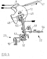
- the control unit 4, as illustrated in FIG. 3, is designed with an additional, third control disk 12. This is shown in a rear view now in Fig. 5.
- the third control disk 12 is arranged on the, the first control disk 5 opposite side of the second control disk 6 and also hinged to the common control axis 64 rotatably.
- the effective conclusion for a common rotation of the second control disk 6 and the third control disk 12 is realized via a second clutch lever 50, wherein this operative conclusion is carried out according to the between the first control disk 5 and the second control disk 6.
- a portion of the second control lever 50 is in turn movable in a second guide 48 of the second control disk 6, so that it is displaced in the decoupled state upward along the arrow shown in white and positioned in the second recess 49, for example, if a movement via an internal operating lever 47th is introduced into the third control disk 12.
- a fourth inactivation mechanism 22 and a fifth inactivation mechanism 23 are provided with respect to this second clutch lever 50.
- the fourth deactivation mechanism 22 takes into account a manual parental control. If this is activated, for example by the parental lock lever 54 is moved in the manner indicated by a double arrow, the second driver 51 rotates about its axis of rotation and engages (below) on the second clutch lever 50 and moves it in the desired manner.
- the second driver 51 is executed only on one side, so that it is ensured, for example by a suitable spring bias of the second clutch lever 50, that this retracts into the illustrated position when the child-safety lever 54 is moved back.
- this movement of the second clutch lever 50 can also be carried out using a second motor 19.
- This second motor 19 drives a second worm wheel 52, which transmits its rotation to a second rotary part 53.
- This second rotary member 53 By conditioning this second rotary member 53 to the second clutch lever 50, this can be moved upwards, with the opposite rotation of the second rotary member 53, the spring bias ensures that the second clutch lever 50 moves back again.
- FIG. 3 has been supplemented by further modular assemblies.
- This relates for example to a drive 13 for electrically opening the door lock, or for electrically assisted closing of the door lock. This assembly will be explained below with reference to FIG.
- a third motor 56 is provided in the control unit 4, which is controlled, for example, by a control system 20 comprising various electrical components 55. With this third motor 56, a third worm wheel 57 is driven, which transmits its rotation to a third rotary part 58. Among other things, the multi-part control disk can be driven (directly) via a roller 59 cooperating with the third rotary part 58.
- the third motor 56 is again operable in both directions, so that can be realized for the roller 59, which is engaged with the third rotary member 58, both directions of rotation, as with the differently colored marked Arrows is shown.
- a quick release of the closing elements 3 This means, in particular, that a direct electromotive adjustment of the second control disk 6 via the roller 59 or its cam 60 is caused, leading to the lifting of the pawls of the rotary latches of at least two door locks or for controlling actuating levers, which in turn for opening the locking parts are responsible.
- the scenario in the context of a so-called "keyless entry system” with quick release could thus proceed as follows: A user with an identification transmitter approaches the motor vehicle and presses or touches the outside door handle (outer operating unit), creating a question and answer dialog between, for example, the control system 20 and the identification transmitter is started.
- the roller 59 rotates in the direction of the white arrow, wherein an opening lever 62 is displaced in the direction indicated by the white arrow.
- This relative movement can be exploited to support (indirectly or mechanically) the rotation of the rotary latch from a pre-locking position to a main locking position. Even if only one opening lever 62 is provided here for a single closing element, several such opening levers 62 can nevertheless be connected to the roller 59.
- the rotation or rotation of the second control disk 6 is thereby caused by the first control disk 5, or the illustrated external operating lever 35, and / or the second control disk 12, or the inner operating lever 47.
- a pivotally mounted actuator 14 is shown, which is in contact with the outer contour of the three control discs, in particular when the locking mechanism 15 with the motor vehicle 28 is engaged.
- the deactivation of the locking mechanism 15, which is active only in the fully open position of the sliding door, can take place via an actuating unit, so that the rotation of one, several or all control discs 5, 6, 12 for deflecting the actuator 14 and thus for deactivating the locking mechanism 15 leads.
- the stroke to be realized by the control disks for deactivating the locking mechanism 15 is only as great as an idle stroke with respect to the actuators 65, 66 and 67. This idle stroke results from the deflected position of the pawls in the door lock with the rotary latch open , Thus, the forces occurring in this process are very low.
Landscapes
- Health & Medical Sciences (AREA)
- Child & Adolescent Psychology (AREA)
- Engineering & Computer Science (AREA)
- Structural Engineering (AREA)
- Lock And Its Accessories (AREA)
Applications Claiming Priority (1)
| Application Number | Priority Date | Filing Date | Title |
|---|---|---|---|
| DE200610020344 DE102006020344A1 (de) | 2006-04-28 | 2006-04-28 | Schließsystem für eine Kraftfahrzeugtür mit mehreren Schließelementen und gemeinsamer Steuereinheit |
Publications (3)
| Publication Number | Publication Date |
|---|---|
| EP1854945A2 true EP1854945A2 (fr) | 2007-11-14 |
| EP1854945A3 EP1854945A3 (fr) | 2012-11-28 |
| EP1854945B1 EP1854945B1 (fr) | 2016-07-06 |
Family
ID=38521109
Family Applications (1)
| Application Number | Title | Priority Date | Filing Date |
|---|---|---|---|
| EP07007965.2A Not-in-force EP1854945B1 (fr) | 2006-04-28 | 2007-04-19 | Système de verrouillage pour une porte d'un véhicule automobile avec plusieurs éléments de verrouillage et une unité de contrôle commune |
Country Status (2)
| Country | Link |
|---|---|
| EP (1) | EP1854945B1 (fr) |
| DE (1) | DE102006020344A1 (fr) |
Cited By (2)
| Publication number | Priority date | Publication date | Assignee | Title |
|---|---|---|---|---|
| CN101280652B (zh) * | 2008-06-02 | 2010-11-03 | 孙述堂 | 动车组高速列车门锁 |
| EP2090729A3 (fr) * | 2008-02-18 | 2013-04-03 | Mitsubishi Jidosha Kogyo Kabushiki Kaisha | Système de verrouillage de porte |
Families Citing this family (8)
| Publication number | Priority date | Publication date | Assignee | Title |
|---|---|---|---|---|
| DE202008015789U1 (de) | 2008-11-28 | 2010-04-22 | Kiekert Ag | Kraftfahrzeugtürverschluss |
| DE102010035006A1 (de) | 2010-08-20 | 2012-02-23 | Kiekert Ag | Schließsystem für eine Kraftfahrzeug-Seitentür |
| DE102015002452A1 (de) | 2015-02-25 | 2016-08-25 | Kiekert Aktiengesellschaft | Kraftfahrzeugschloss |
| DE102015002450A1 (de) | 2015-02-25 | 2016-08-25 | Kiekert Aktiengesellschaft | Kraftfahrzeugtürverschluss |
| DE102015002451A1 (de) | 2015-02-25 | 2016-08-25 | Kiekert Aktiengesellschaft | Kraftfahrzeugtürverschluss |
| US11306518B2 (en) | 2017-03-02 | 2022-04-19 | Kiekert Ag | Vehicle door lock, especially tailgate lock |
| DE102022114103A1 (de) | 2022-06-03 | 2023-12-14 | Kiekert Aktiengesellschaft | Kraftfahrzeug-Schloss insbesondere Kraftfahrzeug-Türschloss |
| DE102022120976A1 (de) * | 2022-08-19 | 2024-02-22 | Kiekert Aktiengesellschaft | Kombination aus einem Kraftfahrzeugschloss und einer Kraftfahrzeug-Schloss-Funktionseinheit |
Family Cites Families (3)
| Publication number | Priority date | Publication date | Assignee | Title |
|---|---|---|---|---|
| JP3301700B2 (ja) * | 1996-07-10 | 2002-07-15 | 三井金属鉱業株式会社 | 車両用スライド扉の中継機構 |
| JP3586159B2 (ja) * | 1999-12-22 | 2004-11-10 | アイシン精機株式会社 | 車両用ドア開閉装置 |
| JP4072115B2 (ja) * | 2003-11-11 | 2008-04-09 | 三井金属鉱業株式会社 | ドア開閉装置 |
-
2006
- 2006-04-28 DE DE200610020344 patent/DE102006020344A1/de not_active Withdrawn
-
2007
- 2007-04-19 EP EP07007965.2A patent/EP1854945B1/fr not_active Not-in-force
Non-Patent Citations (1)
| Title |
|---|
| None |
Cited By (2)
| Publication number | Priority date | Publication date | Assignee | Title |
|---|---|---|---|---|
| EP2090729A3 (fr) * | 2008-02-18 | 2013-04-03 | Mitsubishi Jidosha Kogyo Kabushiki Kaisha | Système de verrouillage de porte |
| CN101280652B (zh) * | 2008-06-02 | 2010-11-03 | 孙述堂 | 动车组高速列车门锁 |
Also Published As
| Publication number | Publication date |
|---|---|
| EP1854945B1 (fr) | 2016-07-06 |
| EP1854945A3 (fr) | 2012-11-28 |
| DE102006020344A1 (de) | 2007-10-31 |
Similar Documents
| Publication | Publication Date | Title |
|---|---|---|
| EP1854945B1 (fr) | Système de verrouillage pour une porte d'un véhicule automobile avec plusieurs éléments de verrouillage et une unité de contrôle commune | |
| EP3612695B1 (fr) | Serrure de véhicule automobile | |
| EP1922464B1 (fr) | Vehicule automobile et serrure de portiere pour une portiere d'un vehicule automobile | |
| DE102018117107A1 (de) | Fahrzeug-verschlussverriegelungsanordnung mit verriegelungsmechanismus vom rollentyp und anzugmechanismus | |
| EP3942138B1 (fr) | Dispositif d'ouverture pour un élément de porte de véhicule à moteur | |
| DE102017222351A1 (de) | Intelligenter riegel | |
| EP3194695A1 (fr) | Système de poignée de portière pour un véhicule automobile | |
| DE102005024899A1 (de) | Kraftfahrzeugschloss | |
| DE102017108265A1 (de) | Schloss für ein Kraftfahrzeug | |
| DE102018120697A1 (de) | Federunterstütztes Stellglied für Kraft-Löse- und/oder Anzugsfunktionalität | |
| EP0721038A1 (fr) | Dispositif de serrure de porte pour hayon arrière double d'un véhicule automobile | |
| EP3173554B2 (fr) | Serrure de véhicule automobile | |
| EP3807482B1 (fr) | Dispositif de fermeture de porte de véhicule à moteur | |
| WO2015027984A1 (fr) | Serrure électrique à déverrouillage d'urgence pour véhicule à moteur | |
| DE19841729B4 (de) | Griffanordnung für ein bewegliches Karosserieteil | |
| EP1039080B1 (fr) | Système de verrouillage central pour véhicule automobile | |
| DE102017101703A1 (de) | Schloss mit Zuzieheinrichtung für ein Kraftfahrzeug | |
| EP2570573B1 (fr) | Serrure de véhicule automobile | |
| EP1012431A1 (fr) | Serrure a commande electrique | |
| EP1710107B1 (fr) | Porte latérale pour un véhicule | |
| EP1849940B1 (fr) | Dispositif de verrouillage pour une porte coulissante avec des moyens de blocage pour maintenir la porte dans sa position ouverte | |
| DE102019121620A1 (de) | Verschlusspaneel für kraftfahrzeuge mit einklemm-schutzschild und einklemm-schutzschild für verschlusspaneele | |
| EP3059361A1 (fr) | Serrure de véhicule automobile | |
| DE102024101536A1 (de) | Kraftfahrzeugschloss für ein Verschlusselement eines Kraftfahrzeugs | |
| DE102006053133A1 (de) | Schließvorrichtung für eine Schiebetür mit Arretierungsmitteln sowie Verfahren zum Betätigen von Arretierungsmitteln einer Schiebetür |
Legal Events
| Date | Code | Title | Description |
|---|---|---|---|
| PUAI | Public reference made under article 153(3) epc to a published international application that has entered the european phase |
Free format text: ORIGINAL CODE: 0009012 |
|
| AK | Designated contracting states |
Kind code of ref document: A2 Designated state(s): AT BE BG CH CY CZ DE DK EE ES FI FR GB GR HU IE IS IT LI LT LU LV MC MT NL PL PT RO SE SI SK TR |
|
| AX | Request for extension of the european patent |
Extension state: AL BA HR MK YU |
|
| RAP1 | Party data changed (applicant data changed or rights of an application transferred) |
Owner name: KIEKERT AKTIENGESELLSCHAFT |
|
| PUAL | Search report despatched |
Free format text: ORIGINAL CODE: 0009013 |
|
| AK | Designated contracting states |
Kind code of ref document: A3 Designated state(s): AT BE BG CH CY CZ DE DK EE ES FI FR GB GR HU IE IS IT LI LT LU LV MC MT NL PL PT RO SE SI SK TR |
|
| AX | Request for extension of the european patent |
Extension state: AL BA HR MK RS |
|
| RIC1 | Information provided on ipc code assigned before grant |
Ipc: E05B 63/14 20060101ALI20121023BHEP Ipc: E05B 47/00 20060101ALI20121023BHEP Ipc: E05B 65/12 20060101AFI20121023BHEP |
|
| 17P | Request for examination filed |
Effective date: 20130422 |
|
| AKX | Designation fees paid |
Designated state(s): AT BE BG CH CY CZ DE DK EE ES FI FR GB GR HU IE IS IT LI LT LU LV MC MT NL PL PT RO SE SI SK TR |
|
| 17Q | First examination report despatched |
Effective date: 20131105 |
|
| REG | Reference to a national code |
Ref country code: DE Ref legal event code: R079 Ref document number: 502007014918 Country of ref document: DE Free format text: PREVIOUS MAIN CLASS: E05B0065120000 Ipc: E05B0081060000 |
|
| GRAP | Despatch of communication of intention to grant a patent |
Free format text: ORIGINAL CODE: EPIDOSNIGR1 |
|
| RIC1 | Information provided on ipc code assigned before grant |
Ipc: E05B 83/40 20140101ALN20160205BHEP Ipc: E05B 81/14 20140101ALN20160205BHEP Ipc: E05B 81/20 20140101ALN20160205BHEP Ipc: E05B 85/00 20140101ALN20160205BHEP Ipc: E05B 77/26 20140101ALI20160205BHEP Ipc: E05B 81/06 20140101AFI20160205BHEP Ipc: E05B 63/14 20060101ALI20160205BHEP |
|
| INTG | Intention to grant announced |
Effective date: 20160224 |
|
| GRAS | Grant fee paid |
Free format text: ORIGINAL CODE: EPIDOSNIGR3 |
|
| GRAA | (expected) grant |
Free format text: ORIGINAL CODE: 0009210 |
|
| AK | Designated contracting states |
Kind code of ref document: B1 Designated state(s): AT BE BG CH CY CZ DE DK EE ES FI FR GB GR HU IE IS IT LI LT LU LV MC MT NL PL PT RO SE SI SK TR |
|
| REG | Reference to a national code |
Ref country code: GB Ref legal event code: FG4D Free format text: NOT ENGLISH |
|
| REG | Reference to a national code |
Ref country code: AT Ref legal event code: REF Ref document number: 810848 Country of ref document: AT Kind code of ref document: T Effective date: 20160715 Ref country code: CH Ref legal event code: EP |
|
| REG | Reference to a national code |
Ref country code: IE Ref legal event code: FG4D Free format text: LANGUAGE OF EP DOCUMENT: GERMAN |
|
| REG | Reference to a national code |
Ref country code: DE Ref legal event code: R096 Ref document number: 502007014918 Country of ref document: DE |
|
| REG | Reference to a national code |
Ref country code: NL Ref legal event code: MP Effective date: 20160706 |
|
| REG | Reference to a national code |
Ref country code: LT Ref legal event code: MG4D |
|
| PG25 | Lapsed in a contracting state [announced via postgrant information from national office to epo] |
Ref country code: NL Free format text: LAPSE BECAUSE OF FAILURE TO SUBMIT A TRANSLATION OF THE DESCRIPTION OR TO PAY THE FEE WITHIN THE PRESCRIBED TIME-LIMIT Effective date: 20160706 Ref country code: IS Free format text: LAPSE BECAUSE OF FAILURE TO SUBMIT A TRANSLATION OF THE DESCRIPTION OR TO PAY THE FEE WITHIN THE PRESCRIBED TIME-LIMIT Effective date: 20161106 Ref country code: FI Free format text: LAPSE BECAUSE OF FAILURE TO SUBMIT A TRANSLATION OF THE DESCRIPTION OR TO PAY THE FEE WITHIN THE PRESCRIBED TIME-LIMIT Effective date: 20160706 Ref country code: IT Free format text: LAPSE BECAUSE OF FAILURE TO SUBMIT A TRANSLATION OF THE DESCRIPTION OR TO PAY THE FEE WITHIN THE PRESCRIBED TIME-LIMIT Effective date: 20160706 Ref country code: LT Free format text: LAPSE BECAUSE OF FAILURE TO SUBMIT A TRANSLATION OF THE DESCRIPTION OR TO PAY THE FEE WITHIN THE PRESCRIBED TIME-LIMIT Effective date: 20160706 |
|
| PG25 | Lapsed in a contracting state [announced via postgrant information from national office to epo] |
Ref country code: ES Free format text: LAPSE BECAUSE OF FAILURE TO SUBMIT A TRANSLATION OF THE DESCRIPTION OR TO PAY THE FEE WITHIN THE PRESCRIBED TIME-LIMIT Effective date: 20160706 Ref country code: PL Free format text: LAPSE BECAUSE OF FAILURE TO SUBMIT A TRANSLATION OF THE DESCRIPTION OR TO PAY THE FEE WITHIN THE PRESCRIBED TIME-LIMIT Effective date: 20160706 Ref country code: GR Free format text: LAPSE BECAUSE OF FAILURE TO SUBMIT A TRANSLATION OF THE DESCRIPTION OR TO PAY THE FEE WITHIN THE PRESCRIBED TIME-LIMIT Effective date: 20161007 Ref country code: LV Free format text: LAPSE BECAUSE OF FAILURE TO SUBMIT A TRANSLATION OF THE DESCRIPTION OR TO PAY THE FEE WITHIN THE PRESCRIBED TIME-LIMIT Effective date: 20160706 Ref country code: PT Free format text: LAPSE BECAUSE OF FAILURE TO SUBMIT A TRANSLATION OF THE DESCRIPTION OR TO PAY THE FEE WITHIN THE PRESCRIBED TIME-LIMIT Effective date: 20161107 Ref country code: SE Free format text: LAPSE BECAUSE OF FAILURE TO SUBMIT A TRANSLATION OF THE DESCRIPTION OR TO PAY THE FEE WITHIN THE PRESCRIBED TIME-LIMIT Effective date: 20160706 |
|
| REG | Reference to a national code |
Ref country code: DE Ref legal event code: R097 Ref document number: 502007014918 Country of ref document: DE |
|
| PG25 | Lapsed in a contracting state [announced via postgrant information from national office to epo] |
Ref country code: RO Free format text: LAPSE BECAUSE OF FAILURE TO SUBMIT A TRANSLATION OF THE DESCRIPTION OR TO PAY THE FEE WITHIN THE PRESCRIBED TIME-LIMIT Effective date: 20160706 Ref country code: EE Free format text: LAPSE BECAUSE OF FAILURE TO SUBMIT A TRANSLATION OF THE DESCRIPTION OR TO PAY THE FEE WITHIN THE PRESCRIBED TIME-LIMIT Effective date: 20160706 |
|
| PLBE | No opposition filed within time limit |
Free format text: ORIGINAL CODE: 0009261 |
|
| STAA | Information on the status of an ep patent application or granted ep patent |
Free format text: STATUS: NO OPPOSITION FILED WITHIN TIME LIMIT |
|
| PG25 | Lapsed in a contracting state [announced via postgrant information from national office to epo] |
Ref country code: BG Free format text: LAPSE BECAUSE OF FAILURE TO SUBMIT A TRANSLATION OF THE DESCRIPTION OR TO PAY THE FEE WITHIN THE PRESCRIBED TIME-LIMIT Effective date: 20161006 Ref country code: DK Free format text: LAPSE BECAUSE OF FAILURE TO SUBMIT A TRANSLATION OF THE DESCRIPTION OR TO PAY THE FEE WITHIN THE PRESCRIBED TIME-LIMIT Effective date: 20160706 Ref country code: CZ Free format text: LAPSE BECAUSE OF FAILURE TO SUBMIT A TRANSLATION OF THE DESCRIPTION OR TO PAY THE FEE WITHIN THE PRESCRIBED TIME-LIMIT Effective date: 20160706 Ref country code: SK Free format text: LAPSE BECAUSE OF FAILURE TO SUBMIT A TRANSLATION OF THE DESCRIPTION OR TO PAY THE FEE WITHIN THE PRESCRIBED TIME-LIMIT Effective date: 20160706 |
|
| 26N | No opposition filed |
Effective date: 20170407 |
|
| PG25 | Lapsed in a contracting state [announced via postgrant information from national office to epo] |
Ref country code: SI Free format text: LAPSE BECAUSE OF FAILURE TO SUBMIT A TRANSLATION OF THE DESCRIPTION OR TO PAY THE FEE WITHIN THE PRESCRIBED TIME-LIMIT Effective date: 20160706 |
|
| REG | Reference to a national code |
Ref country code: DE Ref legal event code: R119 Ref document number: 502007014918 Country of ref document: DE |
|
| REG | Reference to a national code |
Ref country code: CH Ref legal event code: PL |
|
| GBPC | Gb: european patent ceased through non-payment of renewal fee |
Effective date: 20170419 |
|
| REG | Reference to a national code |
Ref country code: IE Ref legal event code: MM4A |
|
| REG | Reference to a national code |
Ref country code: FR Ref legal event code: ST Effective date: 20171229 |
|
| PG25 | Lapsed in a contracting state [announced via postgrant information from national office to epo] |
Ref country code: DE Free format text: LAPSE BECAUSE OF NON-PAYMENT OF DUE FEES Effective date: 20171103 Ref country code: MC Free format text: LAPSE BECAUSE OF FAILURE TO SUBMIT A TRANSLATION OF THE DESCRIPTION OR TO PAY THE FEE WITHIN THE PRESCRIBED TIME-LIMIT Effective date: 20160706 Ref country code: FR Free format text: LAPSE BECAUSE OF NON-PAYMENT OF DUE FEES Effective date: 20170502 |
|
| PG25 | Lapsed in a contracting state [announced via postgrant information from national office to epo] |
Ref country code: LU Free format text: LAPSE BECAUSE OF NON-PAYMENT OF DUE FEES Effective date: 20170419 Ref country code: GB Free format text: LAPSE BECAUSE OF NON-PAYMENT OF DUE FEES Effective date: 20170419 Ref country code: LI Free format text: LAPSE BECAUSE OF NON-PAYMENT OF DUE FEES Effective date: 20170430 Ref country code: CH Free format text: LAPSE BECAUSE OF NON-PAYMENT OF DUE FEES Effective date: 20170430 |
|
| REG | Reference to a national code |
Ref country code: BE Ref legal event code: MM Effective date: 20170430 |
|
| PG25 | Lapsed in a contracting state [announced via postgrant information from national office to epo] |
Ref country code: IE Free format text: LAPSE BECAUSE OF NON-PAYMENT OF DUE FEES Effective date: 20170419 |
|
| PG25 | Lapsed in a contracting state [announced via postgrant information from national office to epo] |
Ref country code: BE Free format text: LAPSE BECAUSE OF NON-PAYMENT OF DUE FEES Effective date: 20170430 |
|
| REG | Reference to a national code |
Ref country code: AT Ref legal event code: MM01 Ref document number: 810848 Country of ref document: AT Kind code of ref document: T Effective date: 20170419 |
|
| PG25 | Lapsed in a contracting state [announced via postgrant information from national office to epo] |
Ref country code: AT Free format text: LAPSE BECAUSE OF NON-PAYMENT OF DUE FEES Effective date: 20170419 |
|
| PG25 | Lapsed in a contracting state [announced via postgrant information from national office to epo] |
Ref country code: MT Free format text: LAPSE BECAUSE OF FAILURE TO SUBMIT A TRANSLATION OF THE DESCRIPTION OR TO PAY THE FEE WITHIN THE PRESCRIBED TIME-LIMIT Effective date: 20160706 |
|
| PG25 | Lapsed in a contracting state [announced via postgrant information from national office to epo] |
Ref country code: HU Free format text: LAPSE BECAUSE OF FAILURE TO SUBMIT A TRANSLATION OF THE DESCRIPTION OR TO PAY THE FEE WITHIN THE PRESCRIBED TIME-LIMIT; INVALID AB INITIO Effective date: 20070419 |
|
| PG25 | Lapsed in a contracting state [announced via postgrant information from national office to epo] |
Ref country code: CY Free format text: LAPSE BECAUSE OF NON-PAYMENT OF DUE FEES Effective date: 20160706 |
|
| PG25 | Lapsed in a contracting state [announced via postgrant information from national office to epo] |
Ref country code: TR Free format text: LAPSE BECAUSE OF FAILURE TO SUBMIT A TRANSLATION OF THE DESCRIPTION OR TO PAY THE FEE WITHIN THE PRESCRIBED TIME-LIMIT Effective date: 20160706 |