EP1855026A2 - Chaîne à plaquettes - Google Patents
Chaîne à plaquettes Download PDFInfo
- Publication number
- EP1855026A2 EP1855026A2 EP07007989A EP07007989A EP1855026A2 EP 1855026 A2 EP1855026 A2 EP 1855026A2 EP 07007989 A EP07007989 A EP 07007989A EP 07007989 A EP07007989 A EP 07007989A EP 1855026 A2 EP1855026 A2 EP 1855026A2
- Authority
- EP
- European Patent Office
- Prior art keywords
- chain
- damping
- lashing
- chain according
- tabs
- Prior art date
- Legal status (The legal status is an assumption and is not a legal conclusion. Google has not performed a legal analysis and makes no representation as to the accuracy of the status listed.)
- Withdrawn
Links
- 238000013016 damping Methods 0.000 claims abstract description 84
- 238000005452 bending Methods 0.000 claims description 4
- 238000010516 chain-walking reaction Methods 0.000 claims description 3
- 230000005489 elastic deformation Effects 0.000 claims description 3
- 238000009434 installation Methods 0.000 claims description 2
- 239000000463 material Substances 0.000 description 9
- 238000005096 rolling process Methods 0.000 description 5
- 239000005060 rubber Substances 0.000 description 5
- 229910000831 Steel Inorganic materials 0.000 description 4
- 239000010959 steel Substances 0.000 description 4
- 239000002131 composite material Substances 0.000 description 3
- 230000000694 effects Effects 0.000 description 3
- 230000005540 biological transmission Effects 0.000 description 2
- 238000005553 drilling Methods 0.000 description 2
- 239000013013 elastic material Substances 0.000 description 2
- 230000010355 oscillation Effects 0.000 description 2
- 239000004033 plastic Substances 0.000 description 2
- 229920003023 plastic Polymers 0.000 description 2
- 238000005303 weighing Methods 0.000 description 2
- 208000035874 Excoriation Diseases 0.000 description 1
- 241001125879 Gobio Species 0.000 description 1
- 238000005299 abrasion Methods 0.000 description 1
- 238000004026 adhesive bonding Methods 0.000 description 1
- 230000006835 compression Effects 0.000 description 1
- 238000007906 compression Methods 0.000 description 1
- 230000007613 environmental effect Effects 0.000 description 1
- 230000005284 excitation Effects 0.000 description 1
- 239000003365 glass fiber Substances 0.000 description 1
- 239000000203 mixture Substances 0.000 description 1
- 239000006223 plastic coating Substances 0.000 description 1
- 239000007787 solid Substances 0.000 description 1
- 238000004073 vulcanization Methods 0.000 description 1
Images




Classifications
-
- F—MECHANICAL ENGINEERING; LIGHTING; HEATING; WEAPONS; BLASTING
- F16—ENGINEERING ELEMENTS AND UNITS; GENERAL MEASURES FOR PRODUCING AND MAINTAINING EFFECTIVE FUNCTIONING OF MACHINES OR INSTALLATIONS; THERMAL INSULATION IN GENERAL
- F16G—BELTS, CABLES, OR ROPES, PREDOMINANTLY USED FOR DRIVING PURPOSES; CHAINS; FITTINGS PREDOMINANTLY USED THEREFOR
- F16G13/00—Chains
- F16G13/18—Chains having special overall characteristics
-
- F—MECHANICAL ENGINEERING; LIGHTING; HEATING; WEAPONS; BLASTING
- F16—ENGINEERING ELEMENTS AND UNITS; GENERAL MEASURES FOR PRODUCING AND MAINTAINING EFFECTIVE FUNCTIONING OF MACHINES OR INSTALLATIONS; THERMAL INSULATION IN GENERAL
- F16G—BELTS, CABLES, OR ROPES, PREDOMINANTLY USED FOR DRIVING PURPOSES; CHAINS; FITTINGS PREDOMINANTLY USED THEREFOR
- F16G13/00—Chains
- F16G13/02—Driving-chains
-
- F—MECHANICAL ENGINEERING; LIGHTING; HEATING; WEAPONS; BLASTING
- F16—ENGINEERING ELEMENTS AND UNITS; GENERAL MEASURES FOR PRODUCING AND MAINTAINING EFFECTIVE FUNCTIONING OF MACHINES OR INSTALLATIONS; THERMAL INSULATION IN GENERAL
- F16G—BELTS, CABLES, OR ROPES, PREDOMINANTLY USED FOR DRIVING PURPOSES; CHAINS; FITTINGS PREDOMINANTLY USED THEREFOR
- F16G13/00—Chains
- F16G13/02—Driving-chains
- F16G13/04—Toothed chains
Definitions
- the present invention relates to a link chain of a plurality of tabs, each forming chain links, which are connected by a hinge in each case with an adjacent chain link.
- a generic link chain is for example in the DE 100 22 844 disclosed.
- the problem arises that line oscillations can occur when looping conical disks, toothed wheels, friction wheels or the like.
- Chain-core vibrations are caused by the introduction of force on the chain links when entering or leaving the chain, for example in the sprocket of a toothed chain drive or the pulley set of a CVT (Continuously Variable Transmission) transmission.
- the impact of the tooth flanks in connection with the polygonal effect of the link chain stimulates the chain center to vibrate.
- Object of the present invention is therefore to provide a plate link chain, which causes a reliable damping of Trumschwingungen with a simple design.
- link chain is understood here, of course, a toothed link chain.
- the buckling movement is a rotation of two adjacent chain links about the joint connecting both, for example, in the wrapping of a gear, friction wheel, conical disk or the like as in the example DE 100 22 844 is shown in Fig. 1.
- Such a buckling or bending movement is possible in the direction of the looping and in particular in both strands in the opposite direction during operation.
- the damping straps damp a buckling of the link chain in at least one direction.
- the damping is effected by an elastic deformation of the damping straps. In this case, only portions of the tabs can be deformed.
- the damping tabs extend over in each case two adjacent chain links. The damping tabs have twice as long pitch as the tabs.
- At least one row of damping straps is arranged in the link chain. It is preferably provided that two rows of damping straps are arranged in the link chain. The two rows are preferably offset from one another.
- the respective two tabs covering the damping tabs are therefore not viewed from the side of the tab chain congruent, but each overlapping arranged. It is preferably provided that the two rows form end tabs of the plate-link chain. End tabs are the tabs arranged on both sides of the tab chain on the outside. It is preferably provided that the damping straps of one row damps the buckling movement of the chain in one buckling direction and the damping straps of the other row damp the buckling movement in the other direction. The two rows have different damping tabs. Alternatively it can be provided that the two rows have the same damping tabs. The damping tabs are then preferably oriented differently.
- the damping tabs comprise two eyes which are connected to one another with a back.
- the eyes preferably surround the two outer bolts of two adjacent chain links in the direction of travel.
- the back may comprise two arcuate back pieces. This is particularly advantageous when the back is in the looping of a bevel gear, friction wheel, gear or the like on the inside of the pin or rocker.
- the back are arranged on the side facing in the installation position of the link chain of a rotation axis of a looped chain or friction wheel.
- the back is at a toothed link chain is preferably arranged on the side of the bolt, which faces the teeth.
- the damping straps form a strap strand.
- the tab strand is preferably in one piece and may be e.g. be made as an endless belt.
- the strap strand is symmetrical with respect to an axis of symmetry running in the chain running direction.
- the tab strand preferably has a closure point.
- the link chain comprises two lashing strands and the closure sites of both lashing strands are arranged offset in the chain running direction to each other.
- Fig. 1 shows a side view
- Fig. 2 is a plan view of a toothed plate chain according to the prior art in two-league association.
- the link chain 1 comprises a plurality of tabs 2 and 2 '.
- the tabs 2 and 2 ' are each arranged alternately overlapping and connected with hinge pin 4 as a hinge. Both ends of a tab 2 are thus connected by means of a hinge with one or two tabs 2 '.
- the hinge pins 4 may be in one piece, but are preferably in two parts, wherein a weighing piece 5 is assigned in each case to a lug and rolls on a lug 2 'assigned to an adjacent lug 2'.
- the rocker pieces 5, 5 'each have a rolling profile 7 or 7', with which they can roll or slide on each other.
- the rolling profiles 7, 7 ' may be identical or different. Transversely to the running direction L, this is marked with an arrow with the reference symbol L, the tabs 2 and 2 'are stacked, so that between two transverse to the direction L juxtaposed hinge pin 4 an overlapping arranged tab 2, 2' is arranged.
- the distance T designates the length which a straight line piece, which is formed from one of the chain links 8 or 8 ', has in the case of a folded-in chain.
- the lugs 2 are - as can be seen in Fig. 1 - provided with a toothed link chain each with tab teeth 3. With a plate chain, the tab teeth 3. With the tab teeth 3, the tab chain 1 with a toothing, z. B. a gear, comb. The division between tabs 2 and 2 'is designed so that a uniform division between the tab teeth 3 results in a stretched chain. The tabs 2 and 2 'are provided with tab teeth 3, so that all tabs and counter tabs are each provided with tab teeth 3. However, it is also possible to provide either only tabs 2 or counter-tabs 2 'with two tab teeth 3 or to provide tabs and counter tabs with only one tab tooth 3. The chain links are closed on both sides by damping straps 6. The toothed link chain according to FIG. 1 and FIG. 2 is shown without damper tabs for the sake of clarity.
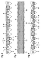
- a toothed plate chain according to the invention is shown.
- This comprises chain links 8 and 8 'as shown in FIGS. 1 and 2.
- the chain links 8 and 8' are provided with damping straps 6.
- the damping tabs 6 close the chain links 8 and 8 'respectively from the side.
- the damping tabs 6 each have twice the pitch of the chain links 8 and 8 '.
- two chain links 8 ' which are connected to a damping tab 6, picked out and designated by the letters A and B.
- the damping tabs 6 each connect two adjacent chain links 8, 8 "with one another in such a way that the respectively outer hinge pins 4 or rocker pieces 5, 5 'are encompassed by a bore 9 or 9' of the damping tab 6.
- the damping tabs form, as shown in FIG.
- R1 and R2 two rows of tabs arranged one after the other in the running direction L are denoted by R1 and R2, and rows of tabs are understood to mean the tabs arranged side by side in the running direction of the chain, the damping tabs 6 each having an eye at its two ends 10 and 10 ', which receives the bores 9 and 9', respectively,
- the two eyes 10, 10 ' are connected to one another by a back 11 which has a thickness D which is approximately equal to the distance d between a chain top edge 12 and that of FIG Chain top edge 12 facing surface of the bolt 4 or
- damping tabs do not protrude beyond the chain top edge 12.
- the thickness D of the spines 11 is greater than the distance d, so that the damping straps 6 protrude beyond the chain top edge.
- the damping tabs 6 are at least between the eyes 10, 10 'of an elastically flexible material, so that in a buckling of the chain 1 and a buckling of the chain link A relative to the chain link B is possible
- the damping straps 6 can be made entirely of an elastic material, for example rubber or a composite material, for example a rubber reinforced with steel.
- the damping tabs 6 but also partially made of different materials, the eyes 10, 10 'are not deformed, for example, at a bend of the chain and can be made of a less elastic material, eg. B. made of steel, the back 11 is deformed at a bend of the chain 1 and may for example consist of rubber or a rubber-steel composite material.
- suitable solid plastics or plastic composite materials for the damping straps 6.
- Fig. 4 the chain 1 shown in the side view of FIG. 3 is shown in plan view.
- the damping tabs 6 are installed offset from one another in order to realize a uniform covering of all the rocker joints, which are formed in pairs by the rocker pieces 5, 5 '.
- This staggered obstruction of the damping tabs 6 can, as shown in the embodiment of FIGS. 3 to 5, take place on the sides of the chain or at any points within the chain.
- the damping tabs 6 could be arranged between the rows of tabs 2 or 2 'designated by 2'.1 and 2.2 or 2'.3 and 2.4, and thus within the chain 1.
- a buckling in the respective opposite direction ie in the damping straps 6, also a buckling direction in the direction of the double arrow 14 and in the damping straps 6.1 also a buckling according to the double arrow 13, is hindered.
- the damping tabs 6.1 have a contour that does not hinder tooth engagement in the teeth 3 of the link chain 1.
- the damping straps 6.1 comprise a spine 11. 1 which connects the eyes 10, 10 'to one another, which is arranged on the side of the hinge pin 4 or gudgeons 5, 5' facing the teeth 3.
- the back 11.1 is in turn divided into two back parts 11.1 a and 11.1 b, which are each arcuate and are connected to one another in a contact point 15. The arcuate design of the backs ensures that they do not cover the spaces between the teeth 3.
- damping tabs 6, 6.1 instead of be installed at the two ends of the link chain 1 between the chain links.
- the respectively arranged on the sides of the link chain 1 free damping tabs 6 and 6.1 are similar to the embodiment of FIG. 3 to 5 arranged overlapping.
- 9 to 11 show a further embodiment of a plate-link chain 1 according to the invention.
- the damping plates 6.1 arranged on both sides according to the embodiment of FIGS. 6 to 8 are only used on one side, as shown in FIG in that these different buckling directions hinder the link chain 1.
- the tab members 18 are connected to each other at connection points 19, 19 a.
- the tab strand 16 may consist of, for example, film material, two films are placed on each other and are connected to each other at the connection points 19, 19 a. In this way, the tab strand 16 has substantially the same total thickness over its entire length.
- the closure points 17 a and 17 b of the two tab strands 16 are each offset from each other, as can be seen from FIGS. 12 to 14.
- the tab strands 16 can be arranged both on the two sides of the link chain 1 and between the individual chain links. It is possible to use only one tab strand instead of two tab strands. In the embodiment of FIGS. 12 to 14, a tab strand 16 is used instead of individual tabs.
- This strand can be mounted over the entire chain length and especially in the application in transfer cases already bring the chain in a form, eg. B. an oval or circular shape. For this purpose, the tab strand in the de-energized and undeformed state, the corresponding oval or circular shape already on.
- the lashing chain according to the invention shows by the application of the tabs or tab straps shown a self-locking against Trumschwingungen.
- the material properties of the elastic tabs should be selected so that they can withstand the environmental conditions of the respective application. Preferably, rubber materials that do not expand at higher temperatures are to be selected. An elongation of the tabs and thus a concomitant reduction in the desired effect of Trumsschwingungsreduzi für .
- the mentioned properties of the Trumschwingungsreduzi für is ensured by a suitable choice of material even at cold temperatures, for this reason, inter alia, on a Mischverbauung (material mix) of the tabs made of different materials, eg. As rubber, steel, glass fiber and the like, are used.
Landscapes
- Engineering & Computer Science (AREA)
- General Engineering & Computer Science (AREA)
- Mechanical Engineering (AREA)
- Devices For Conveying Motion By Means Of Endless Flexible Members (AREA)
- Vibration Dampers (AREA)
Applications Claiming Priority (1)
| Application Number | Priority Date | Filing Date | Title |
|---|---|---|---|
| DE102006021879 | 2006-05-11 |
Publications (1)
| Publication Number | Publication Date |
|---|---|
| EP1855026A2 true EP1855026A2 (fr) | 2007-11-14 |
Family
ID=38279122
Family Applications (1)
| Application Number | Title | Priority Date | Filing Date |
|---|---|---|---|
| EP07007989A Withdrawn EP1855026A2 (fr) | 2006-05-11 | 2007-04-19 | Chaîne à plaquettes |
Country Status (3)
| Country | Link |
|---|---|
| US (1) | US7464810B2 (fr) |
| EP (1) | EP1855026A2 (fr) |
| DE (1) | DE102007018501A1 (fr) |
Cited By (1)
| Publication number | Priority date | Publication date | Assignee | Title |
|---|---|---|---|---|
| WO2021098909A1 (fr) * | 2019-11-22 | 2021-05-27 | Schaeffler Technologies AG & Co. KG | Pièce de pression formant berceau conçue pour une paire de pièces de pression formant berceau d'une chaîne articulée |
Families Citing this family (13)
| Publication number | Priority date | Publication date | Assignee | Title |
|---|---|---|---|---|
| CH704274A1 (de) * | 2010-12-27 | 2012-06-29 | Ferag Ag | Kettenglied einer Förderkette. |
| DE202011103071U1 (de) * | 2011-07-09 | 2011-11-08 | Märtens Transportbänder GmbH | Spreizband |
| USD734590S1 (en) * | 2012-07-24 | 2015-07-14 | Nordischer Maschinenbau Rud. Baader Gmbh + Co. Kg | Chain link |
| DE102012106708A1 (de) | 2012-07-24 | 2014-10-30 | Nordischer Maschinenbau Rud. Baader Gmbh + Co. Kg | Kettenglied, Stützkette und Stützvorrichtung |
| USD731569S1 (en) | 2012-07-24 | 2015-06-09 | Nordischer Maschinenbau Rud. Baader Gmbh + Co. Kg | Sprocket for chain link |
| US10295016B2 (en) | 2014-12-17 | 2019-05-21 | Schaeffler Technologies AG & Co. KG | Plate link chain |
| DE102015201717B4 (de) * | 2015-02-02 | 2017-05-04 | Schaeffler Technologies AG & Co. KG | Umschlingungsmittel mit Laschen und Druckstücken |
| WO2017050325A1 (fr) * | 2015-09-22 | 2017-03-30 | Schaeffler Technologies AG & Co. KG | Chaîne de galle |
| CN106557118B (zh) * | 2015-09-30 | 2024-07-23 | 联想(北京)有限公司 | 电子设备和柔性装置 |
| WO2018167356A1 (fr) * | 2017-03-14 | 2018-09-20 | Finnchain Oy | Pièce de chaîne |
| DE102017113959B4 (de) * | 2017-06-23 | 2019-11-21 | Schaeffler Technologies AG & Co. KG | Laschenkette |
| WO2021021780A1 (fr) | 2019-07-29 | 2021-02-04 | Waters Technologies Corporation | Chaîne de liaison, système de chaîne et procédé |
| JP7387245B2 (ja) | 2020-06-10 | 2023-11-28 | 翔 呉 | ネットチェーン駆動構造 |
Citations (1)
| Publication number | Priority date | Publication date | Assignee | Title |
|---|---|---|---|---|
| DE10022844A1 (de) | 1999-05-14 | 2000-11-16 | Luk Lamellen & Kupplungsbau | Kette |
Family Cites Families (6)
| Publication number | Priority date | Publication date | Assignee | Title |
|---|---|---|---|---|
| US4074085A (en) * | 1976-03-31 | 1978-02-14 | Eli S. Jacobs | Multiple beam optical record playback apparatus for simultaneous scan of plural data tracks |
| US4458809A (en) * | 1981-06-29 | 1984-07-10 | Lear Siegler, Inc. | Padded chain conveyor drive |
| EP0591457B1 (fr) * | 1991-07-03 | 1997-11-12 | HK Systems, Inc. | Transporteur a accumulation de pression nulle |
| US5176246A (en) * | 1992-03-02 | 1993-01-05 | Alvey, Inc. | Padded chain drive for roller conveyors |
| US6308823B1 (en) * | 2000-01-28 | 2001-10-30 | Stevens Design & Fabrication, Inc. | Padded chain for a conveyor |
| WO2005102494A1 (fr) * | 2004-04-14 | 2005-11-03 | Headworks Inc. | Filtre a plaques perforees a flux central |
-
2007
- 2007-04-19 DE DE102007018501A patent/DE102007018501A1/de not_active Withdrawn
- 2007-04-19 EP EP07007989A patent/EP1855026A2/fr not_active Withdrawn
- 2007-05-11 US US11/801,991 patent/US7464810B2/en not_active Expired - Fee Related
Patent Citations (1)
| Publication number | Priority date | Publication date | Assignee | Title |
|---|---|---|---|---|
| DE10022844A1 (de) | 1999-05-14 | 2000-11-16 | Luk Lamellen & Kupplungsbau | Kette |
Cited By (1)
| Publication number | Priority date | Publication date | Assignee | Title |
|---|---|---|---|---|
| WO2021098909A1 (fr) * | 2019-11-22 | 2021-05-27 | Schaeffler Technologies AG & Co. KG | Pièce de pression formant berceau conçue pour une paire de pièces de pression formant berceau d'une chaîne articulée |
Also Published As
| Publication number | Publication date |
|---|---|
| US20070272523A1 (en) | 2007-11-29 |
| US7464810B2 (en) | 2008-12-16 |
| DE102007018501A1 (de) | 2007-11-15 |
Similar Documents
| Publication | Publication Date | Title |
|---|---|---|
| DE102007018501A1 (de) | Laschenkette | |
| DE69023021T2 (de) | Kraftübertragungskette. | |
| DE69712148T2 (de) | Zahnkette mit erhöhten Gliedrücken | |
| DE3413384C2 (de) | Laschenkette für stufenlos verstellbare Kegelscheibengetriebe | |
| DE10118102A1 (de) | Laschenkette | |
| DE10211308B4 (de) | Zahnkette | |
| DE202017101466U1 (de) | Mit einem Kettenantrieb betätigbare rückensteife Schubkette | |
| DE102008058672A1 (de) | Lasche für eine Wiegegelenkkette | |
| DE4332447A1 (de) | Kettenriemen | |
| WO2008095457A1 (fr) | Chaîne à maillons | |
| DE102016207216A1 (de) | Umschlingungsmittel und Bausatz zum Aufbau eines Umschlingungsmittels | |
| DE69205025T2 (de) | Kettenriemen. | |
| DE102009005403A1 (de) | Geräuscharme Kette | |
| DE102009004483A1 (de) | Geräuscharme Kette | |
| EP1819939A1 (fr) | Chaine articulee destinee notamment a une transmission de vehicule | |
| DE102015201717B4 (de) | Umschlingungsmittel mit Laschen und Druckstücken | |
| EP1893890A2 (fr) | Chaine articulee | |
| DE102018106131A1 (de) | Umschlingungsmittel und CVT-Getriebe mit selbigem | |
| WO2007076761A1 (fr) | Chaine articulee | |
| DE102016215952A1 (de) | Umschlingungsmittel und Getriebe mit Umschlingungsmittel | |
| DE102017102210A1 (de) | Lasche für ein als Laschenkette ausgebildetes Umschlingungsmittel, entsprechendes Umschlingungsmittel und Getriebe mit Umschlingungsmittel | |
| DE102018120871A1 (de) | Wiegedruckstückpaar für eine Laschenkette und Umschlingungsmittel mit derartiger Laschenkette | |
| WO2008077365A1 (fr) | Chaîne articulée | |
| DE102012101401A1 (de) | Antriebselement | |
| WO2008034406A1 (fr) | Chaîne à maillons |
Legal Events
| Date | Code | Title | Description |
|---|---|---|---|
| PUAI | Public reference made under article 153(3) epc to a published international application that has entered the european phase |
Free format text: ORIGINAL CODE: 0009012 |
|
| AK | Designated contracting states |
Kind code of ref document: A2 Designated state(s): AT BE BG CH CY CZ DE DK EE ES FI FR GB GR HU IE IS IT LI LT LU LV MC MT NL PL PT RO SE SI SK TR |
|
| AX | Request for extension of the european patent |
Extension state: AL BA HR MK YU |
|
| STAA | Information on the status of an ep patent application or granted ep patent |
Free format text: STATUS: THE APPLICATION IS DEEMED TO BE WITHDRAWN |
|
| 18D | Application deemed to be withdrawn |
Effective date: 20091103 |
|
| P01 | Opt-out of the competence of the unified patent court (upc) registered |
Effective date: 20230522 |