EP1855045A1 - Ständer für Anzeigeeinheit - Google Patents
Ständer für Anzeigeeinheit Download PDFInfo
- Publication number
- EP1855045A1 EP1855045A1 EP07075080A EP07075080A EP1855045A1 EP 1855045 A1 EP1855045 A1 EP 1855045A1 EP 07075080 A EP07075080 A EP 07075080A EP 07075080 A EP07075080 A EP 07075080A EP 1855045 A1 EP1855045 A1 EP 1855045A1
- Authority
- EP
- European Patent Office
- Prior art keywords
- operating lever
- rearward
- elevating member
- pivot bracket
- display unit
- Prior art date
- Legal status (The legal status is an assumption and is not a legal conclusion. Google has not performed a legal analysis and makes no representation as to the accuracy of the status listed.)
- Withdrawn
Links
Images


Classifications
-
- G—PHYSICS
- G06—COMPUTING OR CALCULATING; COUNTING
- G06F—ELECTRIC DIGITAL DATA PROCESSING
- G06F1/00—Details not covered by groups G06F3/00 - G06F13/00 and G06F21/00
- G06F1/16—Constructional details or arrangements
- G06F1/1601—Constructional details related to the housing of computer displays, e.g. of CRT monitors, of flat displays
-
- F—MECHANICAL ENGINEERING; LIGHTING; HEATING; WEAPONS; BLASTING
- F16—ENGINEERING ELEMENTS AND UNITS; GENERAL MEASURES FOR PRODUCING AND MAINTAINING EFFECTIVE FUNCTIONING OF MACHINES OR INSTALLATIONS; THERMAL INSULATION IN GENERAL
- F16M—FRAMES, CASINGS OR BEDS OF ENGINES, MACHINES OR APPARATUS, NOT SPECIFIC TO ENGINES, MACHINES OR APPARATUS PROVIDED FOR ELSEWHERE; STANDS; SUPPORTS
- F16M11/00—Stands or trestles as supports for apparatus or articles placed thereon ; Stands for scientific apparatus such as gravitational force meters
- F16M11/02—Heads
- F16M11/04—Means for attachment of apparatus; Means allowing adjustment of the apparatus relatively to the stand
- F16M11/06—Means for attachment of apparatus; Means allowing adjustment of the apparatus relatively to the stand allowing pivoting
- F16M11/10—Means for attachment of apparatus; Means allowing adjustment of the apparatus relatively to the stand allowing pivoting around a horizontal axis
-
- F—MECHANICAL ENGINEERING; LIGHTING; HEATING; WEAPONS; BLASTING
- F16—ENGINEERING ELEMENTS AND UNITS; GENERAL MEASURES FOR PRODUCING AND MAINTAINING EFFECTIVE FUNCTIONING OF MACHINES OR INSTALLATIONS; THERMAL INSULATION IN GENERAL
- F16M—FRAMES, CASINGS OR BEDS OF ENGINES, MACHINES OR APPARATUS, NOT SPECIFIC TO ENGINES, MACHINES OR APPARATUS PROVIDED FOR ELSEWHERE; STANDS; SUPPORTS
- F16M11/00—Stands or trestles as supports for apparatus or articles placed thereon ; Stands for scientific apparatus such as gravitational force meters
- F16M11/02—Heads
- F16M11/04—Means for attachment of apparatus; Means allowing adjustment of the apparatus relatively to the stand
- F16M11/06—Means for attachment of apparatus; Means allowing adjustment of the apparatus relatively to the stand allowing pivoting
- F16M11/10—Means for attachment of apparatus; Means allowing adjustment of the apparatus relatively to the stand allowing pivoting around a horizontal axis
- F16M11/105—Means for attachment of apparatus; Means allowing adjustment of the apparatus relatively to the stand allowing pivoting around a horizontal axis the horizontal axis being the roll axis, e.g. for creating a landscape-portrait rotation
-
- F—MECHANICAL ENGINEERING; LIGHTING; HEATING; WEAPONS; BLASTING
- F16—ENGINEERING ELEMENTS AND UNITS; GENERAL MEASURES FOR PRODUCING AND MAINTAINING EFFECTIVE FUNCTIONING OF MACHINES OR INSTALLATIONS; THERMAL INSULATION IN GENERAL
- F16M—FRAMES, CASINGS OR BEDS OF ENGINES, MACHINES OR APPARATUS, NOT SPECIFIC TO ENGINES, MACHINES OR APPARATUS PROVIDED FOR ELSEWHERE; STANDS; SUPPORTS
- F16M11/00—Stands or trestles as supports for apparatus or articles placed thereon ; Stands for scientific apparatus such as gravitational force meters
- F16M11/20—Undercarriages with or without wheels
- F16M11/2007—Undercarriages with or without wheels comprising means allowing pivoting adjustment
- F16M11/2021—Undercarriages with or without wheels comprising means allowing pivoting adjustment around a horizontal axis
-
- F—MECHANICAL ENGINEERING; LIGHTING; HEATING; WEAPONS; BLASTING
- F16—ENGINEERING ELEMENTS AND UNITS; GENERAL MEASURES FOR PRODUCING AND MAINTAINING EFFECTIVE FUNCTIONING OF MACHINES OR INSTALLATIONS; THERMAL INSULATION IN GENERAL
- F16M—FRAMES, CASINGS OR BEDS OF ENGINES, MACHINES OR APPARATUS, NOT SPECIFIC TO ENGINES, MACHINES OR APPARATUS PROVIDED FOR ELSEWHERE; STANDS; SUPPORTS
- F16M11/00—Stands or trestles as supports for apparatus or articles placed thereon ; Stands for scientific apparatus such as gravitational force meters
- F16M11/20—Undercarriages with or without wheels
- F16M11/24—Undercarriages with or without wheels changeable in height or length of legs, also for transport only, e.g. by means of tubes screwed into each other
-
- F—MECHANICAL ENGINEERING; LIGHTING; HEATING; WEAPONS; BLASTING
- F16—ENGINEERING ELEMENTS AND UNITS; GENERAL MEASURES FOR PRODUCING AND MAINTAINING EFFECTIVE FUNCTIONING OF MACHINES OR INSTALLATIONS; THERMAL INSULATION IN GENERAL
- F16M—FRAMES, CASINGS OR BEDS OF ENGINES, MACHINES OR APPARATUS, NOT SPECIFIC TO ENGINES, MACHINES OR APPARATUS PROVIDED FOR ELSEWHERE; STANDS; SUPPORTS
- F16M11/00—Stands or trestles as supports for apparatus or articles placed thereon ; Stands for scientific apparatus such as gravitational force meters
- F16M11/20—Undercarriages with or without wheels
- F16M11/24—Undercarriages with or without wheels changeable in height or length of legs, also for transport only, e.g. by means of tubes screwed into each other
- F16M11/26—Undercarriages with or without wheels changeable in height or length of legs, also for transport only, e.g. by means of tubes screwed into each other by telescoping, with or without folding
- F16M11/28—Undercarriages for supports with one single telescoping pillar
-
- F—MECHANICAL ENGINEERING; LIGHTING; HEATING; WEAPONS; BLASTING
- F16—ENGINEERING ELEMENTS AND UNITS; GENERAL MEASURES FOR PRODUCING AND MAINTAINING EFFECTIVE FUNCTIONING OF MACHINES OR INSTALLATIONS; THERMAL INSULATION IN GENERAL
- F16M—FRAMES, CASINGS OR BEDS OF ENGINES, MACHINES OR APPARATUS, NOT SPECIFIC TO ENGINES, MACHINES OR APPARATUS PROVIDED FOR ELSEWHERE; STANDS; SUPPORTS
- F16M2200/00—Details of stands or supports
- F16M2200/04—Balancing means
- F16M2200/044—Balancing means for balancing rotational movement of the undercarriage
-
- F—MECHANICAL ENGINEERING; LIGHTING; HEATING; WEAPONS; BLASTING
- F16—ENGINEERING ELEMENTS AND UNITS; GENERAL MEASURES FOR PRODUCING AND MAINTAINING EFFECTIVE FUNCTIONING OF MACHINES OR INSTALLATIONS; THERMAL INSULATION IN GENERAL
- F16M—FRAMES, CASINGS OR BEDS OF ENGINES, MACHINES OR APPARATUS, NOT SPECIFIC TO ENGINES, MACHINES OR APPARATUS PROVIDED FOR ELSEWHERE; STANDS; SUPPORTS
- F16M2200/00—Details of stands or supports
- F16M2200/08—Foot or support base
Definitions
- the present invention relates to a supporting device for display units and, more particularly, to a supporting device for display units, which can regulate a height of the display unit and rotate the display unit.
- a supporting device for a flat panel display unit such as a liquid crystal display (LCD) or plasma display panel (PDP) functions to regulate the height and viewing angle of a display screen.
- the supporting device also functions to rotate the display screen to be vertically or horizontally oriented, i.e. rotating the display screen vertically or horizontally, as occasion demands.
- Korean Patent Registration Publication No. 10-565686 discloses an example of a supporting device for a display unit capable of regulating a height and viewing angle of a display screen and rotating the screen vertically or horizontally.
- the disclosed supporting device includes an upright stand body, an elevating unit installed to be lifted or lowered along the stand body, and a pivot bracket coupled to an upper end of the elevating unit to rotate about a pivot shaft while being secured to a rear surface of an image display unit.
- the supporting device further includes a locking unit to fixedly maintain the elevating unit in a lifted state or release the fixed state of the elevating unit, and an operating unit to operate the locking unit in accordance with rotation of the pivot bracket when the image display unit is rotated to be vertically or horizontally oriented, i.e. rotated horizontally or vertically.
- the image display unit may be rotated to be vertically oriented only after a height thereof is raised.
- the above described conventional supporting device has a problem in that the locking and operating units, which are used to restrict vertical orientation and height lowering of the image display unit, have a great number of constituent elements, and the connection and arrangement relationship between the elements are very complex, resulting in manufacturing difficulties and high manufacturing costs.
- Exemplary embodiments of the present invention overcome the above disadvantages and other disadvantages not described above. Also, the present invention is not required to overcome the disadvantages described above, and an exemplary embodiment of the present invention may not overcome any of the problems described above.
- an exemplary embodiment of the present invention provides a supporting device for a display unit comprising: a fixed member mounted on a base; an elevating member secured to the fixed member to be lifted or lowered; a pivot bracket rotatably connected to an upper end of the elevating member while being secured to a rear surface of the display unit; an operating lever having an upper portion rotatably coupled to the upper end of the elevating member; a holder formed at the fixed member to allow the operating lever to be caught therein when being rotated rearward in a lifted state of the elevating member; a horizontally movable member secured to the upper end of the elevating member and adapted to move forward and rearward so as to rotate the operating lever; and a cam portion disposed on one of the pivot bracket and the display unit to cause the forward and rearward movements of the horizontally movable member when the pivot bracket is rotated.
- the supporting device may further comprise an elastic member to move the horizontally movable member toward the cam portion.
- the cam portion may have a protruding surface protruded from a rear surface of the pivot bracket, and the horizontally movable member may have a roller to perform a rolling motion while coming into contact with the protruding surface.
- the holder may have: a holding space protruded rearward from an inner surface of an upper end the fixed member to allow a lower end of the operating lever to move rearward; and a supporting surface defining the bottom of the holding space to support the lower end of the operating lever.
- the supporting device may further comprise an elastic member to move the operating lever in a direction of being released from the holder.
- the supporting device may further comprise a connecting member having a rear end secured to the upper end of the elevating member and adapted to pivotally rotate up and down about the upper end of the elevating member and a front end pivotally connected to the pivot bracket.
- the rear end of the connecting member may be adapted to pivotally rotate up and down about a pair of hinged shafts installed on the upper end of the elevating member to regulate a slant of the display screen and the front end of the connecting member is pivotally connected to the pivot bracket by use of a pivot shaft that is disposed in a direction intersecting with the hinged shafts.
- the upper portion of the operating lever may be rotatably coupled to the hinge shafts.
- an exemplary embodiment of the present invention provides a supporting device for a display unit comprising: a fixed member mounted on a base; an elevating member secured to the fixed member to be lifted or lowered; a pivot bracket rotatably connected to an upper end of the elevating member while being secured to a rear surface of the display unit; an operating lever having an upper portion coupled to the upper end of the elevating member to allow forward and rearward movements of the operating lever and a lower portion extending downward by a long distance; a holder formed at the fixed member to allow the operating lever to be caught therein when being moved rearward in a lifted state of the elevating member; a horizontally movable member secured to the upper end of the elevating member and adapted to move forward and rearward so as to move the operating lever forward and rearward; and a cam portion disposed on the pivot bracket or the display unit to cause the forward and rearward movements of the horizontally movable member when the pivot bracket is rotated.
- the operating lever may have a pair of elongated longitudinal coupling slots formed in the upper portion thereof, to be coupled to the hinge shafts so as to move forward and rearward.
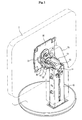
- FIGS. 1 to 6 illustrate a supporting device for a display unit according to a first exemplary embodiment of the present invention.
- the supporting device of the first exemplary embodiment includes a fixed member 10 mounted on a base 1, an elevating member 20 secured to the fixed member 10 to be lifted or lowered, a pivot bracket 30 secured to a rear surface of a display unit 2, and a connecting member 40 adapted to connect an upper end of the elevating member 20 to the pivot bracket 30.
- reference numeral 70 denotes a cover for encasing the supporting device.
- the fixed member 10 is secured, at a lower end thereof, to an upper surface of the base 1 and stands upright to have a long vertical length.
- the fixed member 10 includes first rail portions 11 to guide lifting and lowering of the elevating member 20 while being coupled to the elevating member 20.
- the elevating member 20 has a long vertical length, and includes second rail portions 21 correspondingly coupled to the first rail portions 11 of the fixed member 11.
- the first rail portions 11 of the fixed member 10 and the second rail portions 21 of the elevating member 20 may be directly coupled to each other to perform a relative sliding motion.
- a plurality of balls or rollers may be interposed between the first and second rail portions 11 and 21 for the sake of smooth lifting and lowering of the elevating member 20.
- a pair of lift springs 12 is installed in a space between the fixed member 10 and the elevating member 20 to provide the elevating member 20 with a lifting force.
- Each lift spring 12 takes the form of an elastic windup spring for performing an upward winding and moving motion, and has one end fixed to an upper location of a rear surface of the fixed member 10.
- the elevating member 20 is provided with a pair of spring latches 22.
- Each spring latch 22 is configured to be latched to a winding portion of the associated lift spring 12 such that the lift spring 12 is wound or unwound according to the lifting and lowering behavior of the elevating member 20.
- the lift springs 12 normally act to push up the spring latches 22, thereby providing the elevating member 20 with a lifting force.
- the lift springs 12 push up the elevating member 20 with a force corresponding to the weight of the display unit 2, thereby allowing a user to easily regulate a height of the elevating member 20.
- a lowering force of the elevating member 20 caused by the weight of the display unit 2 may be balanced with the lifting force of the lift springs 12.
- windup springs are provided as one example of the lift springs 12, it should be understood that the lift springs 12 are not limited to this configuration.
- any other members for example, conventional tension coil springs, compression coil springs, or the like, may be used to provide the elevating member 20 with a lifting force.
- the connecting member 40 serves to connect the upper end of the elevating member 20 to the pivot bracket 30.
- the connecting member 40 includes a first connecting portion 40a coupled to a rear surface of the pivot bracket 30, and a pair of second connecting portions 40b extending rearward from opposite lateral sides of the first connecting portion 40a to be coupled to an intermediate connecting member 23 that is located at the upper end of the elevating member 20.
- the first connecting portion 40a is rotatably coupled, at a central portion thereof, to the rear surface of the pivot bracket 30 by use of a pivot shaft 42.
- the second connecting portions 40b are rotatably coupled, at rear ends thereof, to opposite lateral sides of the intermediate connecting member 23 by use of two hinge shafts 41 such that the second connecting portions 40b are pivotally rotated up and down about the two hinge shafts 41.
- the hinge shafts 41 are arranged in a direction of intersecting with the pivot shaft 42.
- the intermediate connecting member 23 has a pair of shaft coupling holes 23a perforated through opposite lateral walls of an upper portion thereof for the coupling of the two hinge shafts 41.
- a lower portion of the intermediate connecting member 23 is fastened to the upper end of the elevating member 20 by use of fixing screws, etc.
- a pair of torsion springs 43 is secured at locations of the intermediate connecting member 23 where the hinge shafts 41 are coupled.
- the torsion springs 43 serve to rotate the connecting member 40 upward in order to prevent droop of the connecting member 40 due to the weight of the display unit 2.
- FIG. 2 illustrates the hinge shafts 41 as being secured to the intermediate connecting member 23 on the upper end of the elevating member 20, the hinge shafts 41 may be directly coupled to the upper end of the elevating member 20.
- a rear end of the connecting member 40 is pivotally rotatable up and down about the hinge shafts 41, thus enabling regulation in a slant of a screen of the display unit 2.
- a front end of the connecting member 40 is coupled to the pivot bracket 30 to rotate the pivot bracket 30 about the pivot shaft 42, thus enabling the screen of the display unit 2 to be rotated so as to be vertically or horizontally oriented, i.e. vertically or horizontally rotated.
- the connecting member 40 is able to realize tilting and pivoting functions.
- the supporting device of this exemplary embodiment may also include a mechanism for rotating the screen of the display unit 2 vertically only when the elevating member 20 is lifted and also, restricting the height regulation of the screen when the screen is vertically oriented.
- the mechanism includes an operating lever 50 having an upper portion rotatably coupled to the upper end of the elevating member 20, a holder 14 provided at an upper end of the rear surface of the fixed member 10 to allow a lower end of the operating lever 50 to be caught by the holder 14, and a horizontally movable member 60 adapted to move forward and rearward in accordance with rotation of the pivot bracket 30 so as to press or release the operating lever 50.
- the operating lever 50 has a connecting portion 51 rotatably coupled to the pivot shafts 41 above the elevating member 20, and an extension 52 extending downward from the connecting portion 51 by a long distance.
- the horizontally movable member 60 is installed above the elevating member 20 to move forward and rearward such that a front end thereof comes close to the rear surface of the pivot bracket 30 and a rear end thereof comes close to the extension 52 of the operating lever 50. That is, the horizontally movable member 60 penetrates through a hole 24 through the intermediate connecting member 23.
- the pivot bracket 30 is formed at the rear surface thereof with a cam portion 31 having a generally arched shape.
- the cam portion 31 has a protruding surface 32 rearwardly protruded from the rear surface of the pivot bracket 30 to cause forward and rearward movements of the horizontally movable member 60 upon rotation of the pivot bracket 30.
- the front end of the horizontally movable member 60 is able to disengage with the cam portion 31.
- the front end of the horizontally movable member 60 comes into contact with the protruding surface 32 of the cam portion 31.
- the front end of the horizontally movable member 60 is provided with a roller 61.
- the roller 61 performs a rolling motion while coming into contact with the cam portion 31, thereby achieving smooth forward and rearward movements of the horizontally movable member 60 in accordance with rotation of the pivot bracket 30.
- a first spring 62 is disposed on the horizontally movable member 60 to move the horizontally movable member 60 toward the cam portion 31.
- the first spring 62 has one end secured to an upper surface of the horizontally movable member 60 and the other end secured to the front end of the connecting member 40, so as to pull the horizontally movable member 60 toward the cam portion 31.
- the horizontally movable member 60 moves rearward to press the operating lever 50. Also, when the long axis of the screen of the display unit 2 is oriented horizontally, i.e. the screen of the display unit 2 is rotated horizontally, the horizontally movable member 60 moves forward to release the operating lever 50.
- the holder 14, as shown in FIG. 6, is formed at the upper end of the rear surface of the fixed member 10 to allow a lower end of the extension 52 of the operating lever 50 to be caught by the holder 14 when the elevating member 20 is lifted.
- the holder 14 has a holding space 14a protruding rearward from an inner surface of the upper end of the fixed member 10 to allow the lower end of the extension 52 of the operating lever 50 to move rearward into the holding space 14a when the operating lever 50 is rotated rearward in accordance with behavior of the horizontally movable member 60.
- the holder 14 further has a supporting surface 14b defining the bottom of the holding space 14a to support the lower end of the extension 52.
- the extension 52 of the operating lever 50 is mounted with a second spring 53.
- the second spring 53 serves to pull the extension 52 forward so as to release the extension 52 from the holder 14 when the operating lever 50 is not pressed by the horizontally movable member 60.
- the second spring 53 has one end connected to the extension 52 and the other end connected to the elevating member 20 to pull the extension 52 forward.
- the pivot bracket 30 is rotated.
- the cam portion 31 formed at the rear surface of the pivot bracket 30 comes into contact with the front end of the horizontally movable member 60 and, thus, the horizontally movable member 60 is moved rearward.
- the operating lever 50 is rotated rearward.
- the front end of the horizontally movable member 60 is disengaged with the cam portion 31. Accordingly, the horizontally movable member 60 is moved forward by the elasticity of the first spring 62, and therefore, the operating lever 50 is not pressed by the horizontally movable member 60. Subsequently, the operating lever 50 is rotated forward by the elasticity of the second spring 53, thereby causing the lower end of the extension 52 to be released from the holder 14.
- the elevating member 20 is able to be lifted or lowered and, thus, the height regulation of the elevating member 20 is possible.
- this exemplary embodiment of the present invention has the effect of preventing the screen of the display unit 2 from being rotated vertically in a lowered state of the elevating member 20 and, therefore, there is no risk of damage to the display unit 2 due to collision with a desk, etc.
- FIGS. 7 and 8 illustrate a supporting device according to a second exemplary embodiment of the present invention.
- an operating lever 80 is configured to perform forward and rearward movements, rather than being rotated, when the horizontally movable member 60 is moved forward and rearward.
- a connecting portion 81 of the operating lever 80 is formed with a pair of elongated longitudinal coupling slots 83 such that the hinge shafts 41 are coupled through the coupling slots 83.
- an extension 82 of the operating lever 80 is provided with a third spring 54 at an upper location thereof, in addition to the second spring 53 provided at a lower location thereof.
- the third spring 54 which is spaced upward from the second spring 53, has one end connected to the extension 82 and the other end connected to the elevating member 20, so as to pull the operating lever 80 forward.
- the operating lever 80 is able to be moved forward by the elasticity of the third and second springs 54 and 53 provided at the upper and lower ends thereof.
- the operating lever 80 when the horizontally movable member 60 is moved rearward in accordance with a rotation of the pivot bracket 30, the operating lever 80 is pushed rearward by the horizontally movable member 60. In this case, the upper and lower ends of the operating lever 80 are moved rearward simultaneously, and in particular, the lower end of the extension 82 is introduced into the holder 14 to be caught by the holder 14. Conversely, when the horizontally movable member 60 is moved forward in accordance with rotation of the pivot bracket 30, the upper and lower ends of the operating lever 80 are pulled forward simultaneously by the elasticity of the second and third springs 53 and 54, thereby releasing the lower end of the extension 82 from the holder 14.
- the supporting device for a display unit may have the effects of allowing a display screen to be rotated so as to be oriented vertically, i.e. rotated vertically, only when an elevating member thereof is lifted, and restricting height regulation of the display screen when the screen is oriented vertically.
- the supporting device of the exemplary embodiments of the present invention include a horizontally movable member to move forward and rearward in accordance with rotation of a pivot bracket, and an operating lever to perform forward and rearward rotation or movement in accordance with behavior of the horizontally movable member.
- the horizontally movable member and operating member With the use of the horizontally movable member and operating member, the overall configuration of the supporting device can be simplified as compared to the prior art while achieving the above described functions with ease.
Landscapes
- Engineering & Computer Science (AREA)
- General Engineering & Computer Science (AREA)
- Mechanical Engineering (AREA)
- Theoretical Computer Science (AREA)
- Computer Hardware Design (AREA)
- Human Computer Interaction (AREA)
- Physics & Mathematics (AREA)
- General Physics & Mathematics (AREA)
- Devices For Indicating Variable Information By Combining Individual Elements (AREA)
Applications Claiming Priority (1)
| Application Number | Priority Date | Filing Date | Title |
|---|---|---|---|
| KR1020060041423A KR101253569B1 (ko) | 2006-05-09 | 2006-05-09 | 디스플레이장치용 지지장치 |
Publications (1)
| Publication Number | Publication Date |
|---|---|
| EP1855045A1 true EP1855045A1 (de) | 2007-11-14 |
Family
ID=38441598
Family Applications (1)
| Application Number | Title | Priority Date | Filing Date |
|---|---|---|---|
| EP07075080A Withdrawn EP1855045A1 (de) | 2006-05-09 | 2007-01-31 | Ständer für Anzeigeeinheit |
Country Status (4)
| Country | Link |
|---|---|
| US (1) | US7815154B2 (de) |
| EP (1) | EP1855045A1 (de) |
| KR (1) | KR101253569B1 (de) |
| CN (1) | CN101071651B (de) |
Cited By (6)
| Publication number | Priority date | Publication date | Assignee | Title |
|---|---|---|---|---|
| EP2038575A4 (de) * | 2006-07-07 | 2011-03-09 | Lg Electronics Inc | Anzeigeeinrichtung |
| CN101469807B (zh) * | 2007-12-29 | 2012-08-22 | 展祥科技(惠州)有限公司 | 平板电视电动遥控壁挂架 |
| CN104536523A (zh) * | 2014-12-23 | 2015-04-22 | 重庆宝丽佰格电子科技有限公司 | 可升降的电脑显示器 |
| EP3508126A1 (de) * | 2018-01-08 | 2019-07-10 | Samsung Medison Co., Ltd. | Unterstützungsvorrichtung für anzeigevorrichtung |
| EP4397899A4 (de) * | 2021-12-27 | 2025-01-08 | Samsung Electronics Co., Ltd. | Anzeigevorrichtung |
| EP4425032A4 (de) * | 2022-04-19 | 2025-03-12 | Samsung Electronics Co., Ltd. | Anzeigevorrichtung |
Families Citing this family (70)
| Publication number | Priority date | Publication date | Assignee | Title |
|---|---|---|---|---|
| KR100609852B1 (ko) * | 2004-05-04 | 2006-08-08 | 삼성전자주식회사 | 디스플레이장치 |
| TWM274544U (en) * | 2005-04-04 | 2005-09-01 | Fulfil Tech Co Ltd | Supporting device capable of adjusting elevation range and display module using same |
| JP4796837B2 (ja) * | 2005-12-27 | 2011-10-19 | Necディスプレイソリューションズ株式会社 | ディスプレイと支持具の連結構造およびディスプレイ |
| KR100800197B1 (ko) * | 2006-07-18 | 2008-02-01 | 엘지전자 주식회사 | 디스플레이 기기의 스탠드 |
| CN2928580Y (zh) * | 2006-08-02 | 2007-08-01 | 明门实业股份有限公司 | 儿童汽车安全座椅的支撑装置 |
| TWM307256U (en) * | 2006-08-16 | 2007-03-01 | Jarllytec Co Ltd | Fastening structure with rapid stevedoring features |
| CN101206927B (zh) * | 2006-12-19 | 2010-05-26 | 鸿富锦精密工业(深圳)有限公司 | 平板显示装置 |
| US7874530B2 (en) * | 2007-04-02 | 2011-01-25 | Samsung Electronics Co., Ltd | Supporter usable with display apparatus |
| CN101335051B (zh) * | 2007-06-29 | 2010-10-06 | 群康科技(深圳)有限公司 | 显示装置 |
| US7510155B2 (en) * | 2007-07-02 | 2009-03-31 | Shian-Nung Huang | Single spring supporting device |
| CN101463938B (zh) * | 2007-12-20 | 2011-07-27 | 鸿富锦精密工业(深圳)有限公司 | 升降机构 |
| US20090166302A1 (en) * | 2007-12-31 | 2009-07-02 | Chin-Jui Hung | Electrically controlled vertically adjustable flat panel display bracket |
| CN101487558B (zh) * | 2008-01-16 | 2012-01-25 | 鸿富锦精密工业(深圳)有限公司 | 升降机构 |
| TWM336658U (en) * | 2008-01-31 | 2008-07-11 | Ming-Hsien Huang | Screen supporting unit |
| CN101504870B (zh) * | 2008-02-05 | 2010-12-08 | 佳世达科技股份有限公司 | 显示装置及其升降机构 |
| CN201185091Y (zh) * | 2008-02-18 | 2009-01-21 | 广州毅昌科技股份有限公司 | 多功能平板显示产品安装底座 |
| US7828255B2 (en) * | 2008-02-19 | 2010-11-09 | Syncmold Enterprise Corp. | Supporting rack having compensating mechanism |
| CN101555977B (zh) * | 2008-04-11 | 2011-06-22 | 鸿富锦精密工业(深圳)有限公司 | 支撑装置 |
| WO2009154337A1 (en) * | 2008-06-16 | 2009-12-23 | Lg Electronics Inc. | Supporting apparatus of display device |
| US7780125B2 (en) * | 2008-07-14 | 2010-08-24 | Syncmold Enterprise Corp. | Support frame for a variety kinds of display devices |
| US7775487B2 (en) * | 2008-09-10 | 2010-08-17 | Syncmold Enterprise Corp. | Foldable supporting stand with positioning means |
| US8157225B2 (en) * | 2009-08-03 | 2012-04-17 | Richard Earl Kephart | Monopod for camera |
| KR20110026655A (ko) * | 2009-09-08 | 2011-03-16 | 삼성전자주식회사 | 영상표시장치의 승강유닛 및 이를 갖는 영상표시장치 |
| US9277812B2 (en) | 2010-07-08 | 2016-03-08 | Southco, Inc. | Display support with first and second arms and mechanism for maintaining constant orientation of the plane bisecting the range of rotation of the second arm relative to a support base |
| CN102375481A (zh) * | 2010-08-17 | 2012-03-14 | 鸿富锦精密工业(深圳)有限公司 | 电子装置 |
| USD662101S1 (en) * | 2010-11-19 | 2012-06-19 | Synexxus, Inc. | Movable mounting arm |
| KR101797241B1 (ko) * | 2011-03-02 | 2017-11-13 | 삼성전자주식회사 | 휴대 단말기의 슬림형 거치대 |
| US20130112828A1 (en) * | 2011-06-07 | 2013-05-09 | Knoll, Inc. | Support Apparatus for Display Devices and Other Objects |
| US9004430B2 (en) * | 2011-09-30 | 2015-04-14 | Imperial Stamping Corporation | Articulating mount for a display |
| JP2015530789A (ja) * | 2012-07-30 | 2015-10-15 | エルゴトロン,インコーポレイティド | モニター用傾動機構 |
| US9456511B2 (en) * | 2012-10-30 | 2016-09-27 | Hewlett-Packard Development Company, L.P. | Support assembly for a device |
| CN103002685B (zh) * | 2012-11-16 | 2015-11-25 | 京东方科技集团股份有限公司 | 一种封装外壳、底座及显示装置 |
| WO2015016837A1 (en) * | 2013-07-30 | 2015-02-05 | Hewlett-Packard Development Company, L.P. | Support assembly for a device |
| US9371955B2 (en) * | 2013-10-07 | 2016-06-21 | Ergotron, Inc. | Bi-directional tilt mechanisms and methods |
| CN103712038B (zh) * | 2013-12-10 | 2015-08-19 | 福建中澳科技有限公司 | 显示器调节定位装置 |
| US9551177B2 (en) * | 2013-12-26 | 2017-01-24 | Intel Corporation | Rotational to translational locking hinge |
| US9512960B2 (en) * | 2014-02-10 | 2016-12-06 | Fuji Xerox Co., Ltd. | Rotational support mechanism |
| TWM486237U (zh) * | 2014-06-06 | 2014-09-11 | Modernsolid Ind Co Ltd | 多功能螢幕支撐裝置 |
| CN105257960B (zh) * | 2014-06-12 | 2018-06-26 | 昆山泓杰电子股份有限公司 | 电视机安装转头 |
| CN104565740A (zh) * | 2014-12-06 | 2015-04-29 | 无锡高卓流体设备有限公司 | 电子电器设备的壁挂件 |
| CN105156852A (zh) * | 2015-07-29 | 2015-12-16 | 山东超越数控电子有限公司 | 一种具有四维调节功能的显示器支架 |
| EP3875829A3 (de) | 2016-03-07 | 2021-10-13 | Southco, Inc. | Stützarmbaugruppe für eine anzeige zur montage einer anzeige |
| US10845000B2 (en) * | 2016-10-21 | 2020-11-24 | Colebrook Bosson Saunders (Products) Limited | Display support system |
| WO2018106806A1 (en) * | 2016-12-07 | 2018-06-14 | Voxx International Corporation | Rotatable antenna mount |
| CN209262585U (zh) * | 2018-01-19 | 2019-08-16 | 信锦企业股份有限公司 | 支撑装置 |
| USD920986S1 (en) * | 2018-03-30 | 2021-06-01 | Humanscale Corporation | Monitor support bracket |
| US11538442B2 (en) | 2018-04-13 | 2022-12-27 | Microsoft Technology Licensing, Llc | Systems and methods of displaying virtual elements on a multipositional display |
| US10890288B2 (en) * | 2018-04-13 | 2021-01-12 | Microsoft Technology Licensing, Llc | Systems and methods of providing a multipositional display |
| DE102018126175A1 (de) * | 2018-10-22 | 2020-04-23 | Bystronic Laser Ag | Pult für eine Bedieneinheit von technischen Anlagen |
| TWM589399U (zh) * | 2018-10-30 | 2020-01-11 | 信錦企業股份有限公司 | 可升降支撐裝置 |
| TWM584074U (zh) * | 2018-12-17 | 2019-09-21 | 信錦企業股份有限公司 | 支撐裝置 |
| TWI698776B (zh) * | 2019-02-01 | 2020-07-11 | 仁寶電腦工業股份有限公司 | 具有升降式顯示器的電子裝置 |
| US11493953B2 (en) | 2019-07-01 | 2022-11-08 | Microsoft Technology Licensing, Llc | Multi-position display with an unfixed center of rotation |
| CN116557694A (zh) * | 2019-07-10 | 2023-08-08 | 爱格升公司 | 显示器安装系统和方法 |
| KR102299514B1 (ko) * | 2019-09-17 | 2021-09-07 | 주식회사 엠에스코리아 | 테이블식 디스플레이 장치 |
| TWI693508B (zh) * | 2019-10-16 | 2020-05-11 | 香港商冠捷投資有限公司 | 顯示裝置 |
| KR102308450B1 (ko) | 2020-03-31 | 2021-10-05 | 엘지전자 주식회사 | 디스플레이 장치 |
| KR102446903B1 (ko) | 2020-06-08 | 2022-09-23 | 엘지전자 주식회사 | 디스플레이 장치 |
| KR102456106B1 (ko) | 2020-07-07 | 2022-10-19 | 엘지전자 주식회사 | 디스플레이 장치 |
| TWI755013B (zh) * | 2020-08-03 | 2022-02-11 | 技嘉科技股份有限公司 | 顯示器支架以及其顯示裝置 |
| CN114123367B (zh) * | 2020-08-31 | 2024-05-07 | 索尼互动娱乐股份有限公司 | 支承装置 |
| CN112747218B (zh) * | 2020-12-01 | 2022-06-28 | 联想(北京)有限公司 | 一种支撑结构、电子设备 |
| US11320088B1 (en) * | 2020-12-07 | 2022-05-03 | Ubtech North America Research And Development Center Corp | Display stand with height adjustment and tilt adjustment |
| CN112923181B (zh) * | 2021-01-26 | 2022-07-05 | 四川职业技术学院 | 一种智能商务英语多义词辨析学习器 |
| CN113503447A (zh) * | 2021-07-27 | 2021-10-15 | 深圳市倍思奇创新科技有限公司 | 角度调节机构及其电视安装支架 |
| EP4350193A4 (de) * | 2021-12-28 | 2024-11-13 | Samsung Electronics Co., Ltd. | Anzeigevorrichtung mit drehvorrichtung für ein rotierendes anzeigemodul |
| WO2023204392A1 (ko) | 2022-04-19 | 2023-10-26 | 삼성전자주식회사 | 디스플레이 장치 |
| WO2023204391A1 (ko) * | 2022-04-19 | 2023-10-26 | 삼성전자주식회사 | 디스플레이 장치 |
| WO2024053815A1 (ko) * | 2022-09-08 | 2024-03-14 | 삼성전자주식회사 | 디스플레이 장치 |
| CN220355017U (zh) * | 2023-07-14 | 2024-01-16 | 兴先达(香港)有限公司 | 移动推车 |
Citations (5)
| Publication number | Priority date | Publication date | Assignee | Title |
|---|---|---|---|---|
| JPH11153960A (ja) * | 1997-11-20 | 1999-06-08 | Nec Home Electron Ltd | 薄型表示装置用スタンド |
| US6189842B1 (en) * | 1999-06-21 | 2001-02-20 | Palo Alto Design Group | Tilt and swivel adjustment of flat panel display having detents for landscape and portrait positions and kickout for preventing contact between flat panel display and base |
| EP1536398A1 (de) * | 2002-08-22 | 2005-06-01 | Sharp Kabushiki Kaisha | Anzeigeeinrichtung des dünnen typs |
| US20060011788A1 (en) * | 2004-06-15 | 2006-01-19 | Se-Ki Jang | Display apparatus |
| EP1626223A2 (de) * | 2004-08-12 | 2006-02-15 | LG Electronics, Inc. | Tragvorrichtung für Bildschirmvorrichtung |
Family Cites Families (3)
| Publication number | Priority date | Publication date | Assignee | Title |
|---|---|---|---|---|
| US5751548A (en) * | 1996-05-13 | 1998-05-12 | International Business Machines Corporation | Docking station for a portable computer providing rotational movement of the computer's viewable screen in three different planes |
| CA2434127A1 (en) * | 2002-07-11 | 2004-01-11 | Peter Martens | Tool support kit |
| TWM274544U (en) * | 2005-04-04 | 2005-09-01 | Fulfil Tech Co Ltd | Supporting device capable of adjusting elevation range and display module using same |
-
2006
- 2006-05-09 KR KR1020060041423A patent/KR101253569B1/ko not_active Expired - Fee Related
-
2007
- 2007-01-16 US US11/653,381 patent/US7815154B2/en not_active Expired - Fee Related
- 2007-01-25 CN CN2007100072086A patent/CN101071651B/zh not_active Expired - Fee Related
- 2007-01-31 EP EP07075080A patent/EP1855045A1/de not_active Withdrawn
Patent Citations (5)
| Publication number | Priority date | Publication date | Assignee | Title |
|---|---|---|---|---|
| JPH11153960A (ja) * | 1997-11-20 | 1999-06-08 | Nec Home Electron Ltd | 薄型表示装置用スタンド |
| US6189842B1 (en) * | 1999-06-21 | 2001-02-20 | Palo Alto Design Group | Tilt and swivel adjustment of flat panel display having detents for landscape and portrait positions and kickout for preventing contact between flat panel display and base |
| EP1536398A1 (de) * | 2002-08-22 | 2005-06-01 | Sharp Kabushiki Kaisha | Anzeigeeinrichtung des dünnen typs |
| US20060011788A1 (en) * | 2004-06-15 | 2006-01-19 | Se-Ki Jang | Display apparatus |
| EP1626223A2 (de) * | 2004-08-12 | 2006-02-15 | LG Electronics, Inc. | Tragvorrichtung für Bildschirmvorrichtung |
Cited By (10)
| Publication number | Priority date | Publication date | Assignee | Title |
|---|---|---|---|---|
| EP2038575A4 (de) * | 2006-07-07 | 2011-03-09 | Lg Electronics Inc | Anzeigeeinrichtung |
| US8033513B2 (en) | 2006-07-07 | 2011-10-11 | Lg Electronics Inc. | Display device |
| CN101469807B (zh) * | 2007-12-29 | 2012-08-22 | 展祥科技(惠州)有限公司 | 平板电视电动遥控壁挂架 |
| CN104536523A (zh) * | 2014-12-23 | 2015-04-22 | 重庆宝丽佰格电子科技有限公司 | 可升降的电脑显示器 |
| EP3508126A1 (de) * | 2018-01-08 | 2019-07-10 | Samsung Medison Co., Ltd. | Unterstützungsvorrichtung für anzeigevorrichtung |
| US10739827B2 (en) | 2018-01-08 | 2020-08-11 | Samsung Medison Co. Ltd. | Supporting device for display device |
| EP4397899A4 (de) * | 2021-12-27 | 2025-01-08 | Samsung Electronics Co., Ltd. | Anzeigevorrichtung |
| EP4425032A4 (de) * | 2022-04-19 | 2025-03-12 | Samsung Electronics Co., Ltd. | Anzeigevorrichtung |
| US12405630B2 (en) | 2022-04-19 | 2025-09-02 | Samsung Electronics Co., Ltd. | Display apparatus |
| EP4671915A3 (de) * | 2022-04-19 | 2026-03-18 | Samsung Electronics Co., Ltd. | Anzeigevorrichtung |
Also Published As
| Publication number | Publication date |
|---|---|
| CN101071651B (zh) | 2010-09-08 |
| CN101071651A (zh) | 2007-11-14 |
| KR101253569B1 (ko) | 2013-04-11 |
| US7815154B2 (en) | 2010-10-19 |
| KR20070109009A (ko) | 2007-11-15 |
| US20070262210A1 (en) | 2007-11-15 |
Similar Documents
| Publication | Publication Date | Title |
|---|---|---|
| US7815154B2 (en) | Supporting device for display unit | |
| US7694919B2 (en) | Stand for display device | |
| EP1832801A2 (de) | Haltevorrichtung für Anzeigevorrichtungen | |
| KR100710313B1 (ko) | 영상표시장치 | |
| KR100705063B1 (ko) | 영상 디스플레이 장치의 스탠드 | |
| US7644897B2 (en) | Display apparatus | |
| KR100628119B1 (ko) | 평판형 모니터 | |
| US20070064379A1 (en) | Display apparatus | |
| US20050051693A1 (en) | Flat panel display | |
| US7213792B2 (en) | Height adjustable and pivotable monitor assembly | |
| US20070217134A1 (en) | Display apparatus | |
| NL1033511C2 (nl) | Liftsysteem voor een paneel en werkwijze voor het vrijgeven en intrekken van een paneel. | |
| US20100188804A1 (en) | Display device | |
| JP4863416B2 (ja) | ディスプレイユニット | |
| JP2003177838A (ja) | 窓口装置 | |
| US20120001044A1 (en) | Display Tilting Device | |
| KR100765242B1 (ko) | 평판형 tv용 벽걸이식 거치대 | |
| JP2010128424A (ja) | スクリーン | |
| US20060255697A1 (en) | Apparatus for moving a cover of furniture | |
| KR100459205B1 (ko) | 평판형 영상표시장치의 받침대 어셈블리 | |
| KR102650851B1 (ko) | 디스플레이용 암 스탠드 | |
| CN213361644U (zh) | 一种支架组件及自助设备 | |
| EP4238618B1 (de) | Faltmechanismus für laufband und laufband | |
| JPH0754536A (ja) | ヒンジ機構 | |
| KR102370573B1 (ko) | 회전가능한 대형 디스플레이 패널용 거치대 |
Legal Events
| Date | Code | Title | Description |
|---|---|---|---|
| PUAI | Public reference made under article 153(3) epc to a published international application that has entered the european phase |
Free format text: ORIGINAL CODE: 0009012 |
|
| AK | Designated contracting states |
Kind code of ref document: A1 Designated state(s): AT BE BG CH CY CZ DE DK EE ES FI FR GB GR HU IE IS IT LI LT LU LV MC NL PL PT RO SE SI SK TR |
|
| AX | Request for extension of the european patent |
Extension state: AL BA HR MK YU |
|
| 17P | Request for examination filed |
Effective date: 20080509 |
|
| 17Q | First examination report despatched |
Effective date: 20080620 |
|
| AKX | Designation fees paid |
Designated state(s): DE GB NL |
|
| RAP1 | Party data changed (applicant data changed or rights of an application transferred) |
Owner name: SAMSUNG ELECTRONICS CO., LTD. |
|
| STAA | Information on the status of an ep patent application or granted ep patent |
Free format text: STATUS: THE APPLICATION IS DEEMED TO BE WITHDRAWN |
|
| 18D | Application deemed to be withdrawn |
Effective date: 20160518 |