EP1855174A1 - Source de rayon laser pour guidage d'un véhicule à marquer - Google Patents
Source de rayon laser pour guidage d'un véhicule à marquer Download PDFInfo
- Publication number
- EP1855174A1 EP1855174A1 EP06113815A EP06113815A EP1855174A1 EP 1855174 A1 EP1855174 A1 EP 1855174A1 EP 06113815 A EP06113815 A EP 06113815A EP 06113815 A EP06113815 A EP 06113815A EP 1855174 A1 EP1855174 A1 EP 1855174A1
- Authority
- EP
- European Patent Office
- Prior art keywords
- beam generator
- reference beam
- legs
- adjustment
- adjustable
- Prior art date
- Legal status (The legal status is an assumption and is not a legal conclusion. Google has not performed a legal analysis and makes no representation as to the accuracy of the status listed.)
- Withdrawn
Links
- 230000008878 coupling Effects 0.000 claims abstract description 3
- 238000010168 coupling process Methods 0.000 claims abstract description 3
- 238000005859 coupling reaction Methods 0.000 claims abstract description 3
- 230000005670 electromagnetic radiation Effects 0.000 claims abstract description 3
- 230000003287 optical effect Effects 0.000 claims description 9
- 230000008859 change Effects 0.000 description 11
- 238000000034 method Methods 0.000 description 4
- 230000008901 benefit Effects 0.000 description 3
- 230000001419 dependent effect Effects 0.000 description 3
- 230000005855 radiation Effects 0.000 description 3
- 208000027418 Wounds and injury Diseases 0.000 description 2
- 230000006378 damage Effects 0.000 description 2
- 238000006073 displacement reaction Methods 0.000 description 2
- 208000014674 injury Diseases 0.000 description 2
- 230000005484 gravity Effects 0.000 description 1
- 238000009434 installation Methods 0.000 description 1
- 230000008569 process Effects 0.000 description 1
- 230000009467 reduction Effects 0.000 description 1
- 238000004904 shortening Methods 0.000 description 1
- 239000002689 soil Substances 0.000 description 1
- 229910000679 solder Inorganic materials 0.000 description 1
- 239000000126 substance Substances 0.000 description 1
Images

Classifications
-
- G—PHYSICS
- G01—MEASURING; TESTING
- G01C—MEASURING DISTANCES, LEVELS OR BEARINGS; SURVEYING; NAVIGATION; GYROSCOPIC INSTRUMENTS; PHOTOGRAMMETRY OR VIDEOGRAMMETRY
- G01C15/00—Surveying instruments or accessories not provided for in groups G01C1/00 - G01C13/00
- G01C15/002—Active optical surveying means
- G01C15/004—Reference lines, planes or sectors
-
- A—HUMAN NECESSITIES
- A63—SPORTS; GAMES; AMUSEMENTS
- A63C—SKATES; SKIS; ROLLER SKATES; DESIGN OR LAYOUT OF COURTS, RINKS OR THE LIKE
- A63C19/00—Design or layout of playing courts, rinks, bowling greens or areas for water-skiing; Covers therefor
- A63C19/06—Apparatus for setting-out or dividing courts
-
- F—MECHANICAL ENGINEERING; LIGHTING; HEATING; WEAPONS; BLASTING
- F16—ENGINEERING ELEMENTS AND UNITS; GENERAL MEASURES FOR PRODUCING AND MAINTAINING EFFECTIVE FUNCTIONING OF MACHINES OR INSTALLATIONS; THERMAL INSULATION IN GENERAL
- F16M—FRAMES, CASINGS OR BEDS OF ENGINES, MACHINES OR APPARATUS, NOT SPECIFIC TO ENGINES, MACHINES OR APPARATUS PROVIDED FOR ELSEWHERE; STANDS; SUPPORTS
- F16M11/00—Stands or trestles as supports for apparatus or articles placed thereon ; Stands for scientific apparatus such as gravitational force meters
- F16M11/02—Heads
- F16M11/04—Means for attachment of apparatus; Means allowing adjustment of the apparatus relatively to the stand
- F16M11/06—Means for attachment of apparatus; Means allowing adjustment of the apparatus relatively to the stand allowing pivoting
- F16M11/10—Means for attachment of apparatus; Means allowing adjustment of the apparatus relatively to the stand allowing pivoting around a horizontal axis
-
- F—MECHANICAL ENGINEERING; LIGHTING; HEATING; WEAPONS; BLASTING
- F16—ENGINEERING ELEMENTS AND UNITS; GENERAL MEASURES FOR PRODUCING AND MAINTAINING EFFECTIVE FUNCTIONING OF MACHINES OR INSTALLATIONS; THERMAL INSULATION IN GENERAL
- F16M—FRAMES, CASINGS OR BEDS OF ENGINES, MACHINES OR APPARATUS, NOT SPECIFIC TO ENGINES, MACHINES OR APPARATUS PROVIDED FOR ELSEWHERE; STANDS; SUPPORTS
- F16M11/00—Stands or trestles as supports for apparatus or articles placed thereon ; Stands for scientific apparatus such as gravitational force meters
- F16M11/20—Undercarriages with or without wheels
- F16M11/24—Undercarriages with or without wheels changeable in height or length of legs, also for transport only, e.g. by means of tubes screwed into each other
- F16M11/26—Undercarriages with or without wheels changeable in height or length of legs, also for transport only, e.g. by means of tubes screwed into each other by telescoping, with or without folding
- F16M11/32—Undercarriages for supports with three or more telescoping legs
- F16M11/36—Members preventing slipping of the feet
-
- G—PHYSICS
- G05—CONTROLLING; REGULATING
- G05D—SYSTEMS FOR CONTROLLING OR REGULATING NON-ELECTRIC VARIABLES
- G05D1/00—Control of position, course, altitude or attitude of land, water, air or space vehicles, e.g. using automatic pilots
- G05D1/02—Control of position or course in two dimensions
- G05D1/021—Control of position or course in two dimensions specially adapted to land vehicles
- G05D1/0231—Control of position or course in two dimensions specially adapted to land vehicles using optical position detecting means
- G05D1/0234—Control of position or course in two dimensions specially adapted to land vehicles using optical position detecting means using optical markers or beacons
- G05D1/0236—Control of position or course in two dimensions specially adapted to land vehicles using optical position detecting means using optical markers or beacons in combination with a laser
Definitions
- the invention relates to a reference beam generator for generating guide beams for the guidance of a marking trolley according to the preamble of claim 1.
- optical guide beams which are generated by a base system and through which a marking car can be performed, as known for example in the WO 2006/013386 is described.
- a device for marking base areas, in particular floors in trade fair halls is described.
- the device automatically controls a self-propelled vehicle along the guide line of a laser beam, wherein a marking device applies markings to the base surface in accordance with a predefinable marking program as a function of the traveled distance.
- the device is particularly intended for the marking of exhibition halls.
- a beam is generated, which serves to define a straight line, for example, one side of a field to be marked.
- the marking trolley used to apply the marking substance has a detector for the laser radiation, whereby the position of the marking trolley relative to the beam is determined, so that the trolley can be automatically controlled by means of the guide beam.
- the laser diode is in this case arranged on a laboratory cart, which in turn is fixed for fixing with respect to a defined position on a base plate with guide rails.
- the optical guide beam must be accurately aligned by means of an adjustment plate, the allowable incident height of the laser beam is limited, since the marking is to remain during the movement in a region of a signal reception.
- the system is limited only for comparatively short distances and level ground, as it is given, for example, within halls.
- An adjustment of the beam over long distances remains problematic, since a laser point must be aligned in two dimensions.
- bumps such as occur in sports fields with natural ground, quickly cause the recipient of the marking car loses the beam.
- one or even two laser beams are emitted in a fan-shaped manner by a reference beam generator, these beacons often being aligned relative to a reference target positioned at a reference point.
- a reference beam generator for example, in the European patent application with the application number 05108174.3 described.
- the reference beam generator has a laser transmitting unit, which comprises a laser and a beam expander for generating a laser fan, preferably also a further optical component - for example a pentaprism - for splitting the laser fan into two partial compartments. Due to the geometric conditions of most sports fields, simultaneous generation and definition of two or more beams or partial beams is advantageous, since two guide beams can thus be used without switching the reference beam generator.
- the generator is designed so that it can be fixed at a defined position, for example by means of a tripod or a carrier plate.
- the fan-beam emitting laser is mounted on a right angle two-leg angle plate such that it emits the laser beam at a defined distance from a line to be marked, according to the structural conditions of the used marking car.
- the detector of the marking trolley is preferably formed as a linear or surface array of photodiodes, which array advantageously on the control unit transverse to the laser transmitting unit of the Reference beam generator clamped laser light plane is arranged.
- the reference beam generator must either be leveled with respect to the gravitational field or aligned with respect to the earth's surface. Since mostly a horizontal, i. inclination-free course of the game is desired, the orientation with respect to the field surface usually coincides with a leveling.
- a simple solution for setting up the reference beam generator would offer itself through the use of firmly positioned and anchored, mechanically strong sockets.
- the sockets arranged in this way are difficult to attach stably in reality, so that a change in position can result from the mechanical load.
- the object of the invention is to provide a reference beam generator, which allows a simplified, more robust and faster determination of guide beams for marking trolley or their leadership.
- a further object of the invention is to provide such a reference beam generator which can be changed in its inclination or the inclination of the guide beams emitted by it, without a significant change in position relative to a reference point.
- the invention is based on the fact that a change in the beam alignment is effected by a coordinated and linked adjustment of two of the at least three legs, wherein an adjustment of one of the two legs is connected to an opposite adjustment of the other leg.
- three-legged systems have the advantage of high stability and ease of placement, their leveling is problematic since the legs each cover an angular range of 120 °.
- An arrangement with four legs and 90 ° is easier to align and to level, but with disadvantages associated with the installation on uneven ground, so that for reference jet generators three-legged solutions have advantages.
- One of the four-legged solution equivalent Adjustability is achieved by the linked counteracting or counteracting adjustment of two of the three legs.
- the length adjustment of the third leg causes a movement orthogonal thereto, so that the combination of two coupled adjustable legs with a third independently adjustable leg has an independent adjustment by two inclination axes result.
- the point can thus be moved on a curved surface or sphere in two orthogonal directions. If the two laser compartments or guide beams are assigned to these inclination degrees of freedom, these can be changed in their inclination independently of one another and thus aligned, with the positioning remaining essentially unchanged with respect to the reference point.
- a mechanical stylus or pointer instead of a laser solder, a mechanical stylus or pointer, e.g. use a telescopic arm or pointer.
- the laser spot or the mechanical pointer moves on a spherical surface or curved surface about the reference point, so that any Deviations largely remain within a tolerable range.
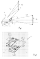
- FIG. 1 schematically illustrates methods for marking sports fields by means of laser fans generated by reference beam generators. Shown is a situation in which a playing field is to be provided with generic markings. In this case, the specification of the line to be marked takes place via a reference beam generator 1, which is to be operated by an operator and positioned on a corner point as a reference point RP. A marking carriage, not shown here, is guided by means of the optical connection emitted by the reference beam generator LS1 and LS2. Since in most cases several lines which are at an angle ⁇ are to be marked, in most cases two guide beams LS1 and LS2 are at a predefined angle, e.g.
- both guide beams LS1 and LS2 must be aligned with respect to the surface or the horizontal and the field geometry to be generated.
- the reference beam generator 1 By one or possibly several repositioning of the reference beam generator 1 finally the entire playing field can be marked.
- the reference beam generator 1 has a housing 1a as a carrier element, which can also be designed as an L-shaped base plate with two legs oriented at right angles to one another as a carrier element. Opposite this against the earth's surface fixable support member, the optical components of the reference beam generator 1 are adjustably mounted, wherein the housing 1a or another Support element itself is positioned by legs 2 opposite the earth's surface. These can be adjusted with respect to the earth's surface, with an exact alignment is required due to the mostly larger structures to be marked.
- a source of electromagnetic radiation such as a laser diode, arranged with beam guiding means for emitting the radiation in two guide beams LS1 and LS2 adjustable.
- the emitted radiation has an asymmetrical beam cross-section 3a and 3b, which is elliptically illustrated here by way of example.
- the beam cross section 3a and 3b can already be provided by a corresponding cross section of the source or be formed after the generation.
- one or more marking trolleys can be guided to produce two lines of the playing field, the generated compartments of the guiding beams LS1 and LS2 providing the planes for orientation and orientation of the marking trolleys.
- the reference beam generator 4 has an L-shaped base plate 5 as a carrier element and a pivotable and displaceable jet unit 6 with source and beam guiding means.
- An orientability of the base plate 5 is ensured by three legs, two of which are adjustable with a spindle in length or relative to the base plate. Due to the adjustment of the legs, first one guide beam and subsequently the second guide beam must now be precisely aligned, with both alignment processes being mutually exclusive influence and lead to a displacement of the base plate 5 with respect to a reference point.
- FIG. 3 illustrates the positioning and alignment of a reference beam generator 1 schematically.
- the reference beam generator 1 has three adjustable legs 2, which serve as positioning elements with respect to the earth's surface EOB.
- the light fans with their beam cross-sections 3a and 3b are arranged in space such that they are fixed with respect to a reference point as a starting point and represent guide beams for guiding a marking trolley.
- the course of the guide beams is usually aligned on the surface of a structure to be marked, ie in an overall inclined pitch the beacons may not be leveled but run according to the surface also inclined.
- a corresponding reference element can be used, as described, for example, in US Pat EP05108174.3 is described.
- an adjustable orientation of the beam cross section can be used for at least one of the guide beams so that it can be aligned, for example, vertically relative to the earth's surface.
- the exact orientation of the guide beam and the beam cross section 3a or 3b is thus dependent on the shape of the bottom, so that corresponding adjustment possibilities - if appropriate in several stages - are advantageous.
- the fast coarse alignment of the entire reference beam generator 1 is always desirable. at short distances or smooth or poorly textured soil conditions, can be done by a single adjustment of the overall system a sufficiently accurate determination of the beacons.
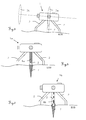
- FIG. 4 shows the schematic representation of a first embodiment of a pointer for a reference beam generator 1a according to the invention.
- the positioning of the reference beam generator 1 takes place with respect to an excellent reference point which can be predetermined, for example, by a peg 7 as a marking.
- Such pegs have the advantage of opposite the ground EOB or its vegetation sunk attachment, so that, for example, overmowing by lawnmowers is possible.
- the buried arrangement and the lack of resilience due to the possible resulting changes in position prevent direct positioning with resilient physical contact with the peg 7.
- a mechanical pointer 8a in particular with orthogonal attachment to the plane defined by the emission directions of the guide beams, for positioning used over a reference point.
- the precise alignment of the pointer tip with respect to the peg 7 can be easily observed from the side, so that a quick and accurate positioning is possible.
- FIG. 8b A second embodiment of a pointer 8b for a reference beam generator 1b according to the invention is shown schematically in FIG.
- the optical pointer 8b is provided in this example by a laser beam emitted perpendicular to the plane defined by the emission directions of the guide beams.
- a user observes the point of the laser beam on the ground EOB and adjusts the reference beam generator 1b until the laser beam hits the peg 7 as centrally as possible.
- FIG. 6 The adjustability according to the invention is explained in FIG. 6 on the basis of the geometric relationships for a reference beam generator according to the invention.
- a plane is spanned, which is exemplified here as an abstract triangle.
- This plane is adjusted after its positioning with respect to a reference point so that the emission directions ER1 and ER2 are aligned by two guide beams relative to the ground or its course.
- An adjustment of the leg 2b causes a change in the inclination of the emission direction ER1 relative to the ground.
- An opposite, in particular equal, change in the linked adjustable legs 2a leads to an increase or decrease in the inclination of the emission direction ER2.
- An associated adjustability causes a coordinated adjustment of both legs 2a takes place, ie the adjustment of a leg 2a is connected to the inevitable and opposite adjustment of the associated other leg 2a.
- the emission direction ER1 of the first guide beam is oriented perpendicular to the axis A connecting the linked adjustable legs 2a and the emission direction ER2 of the second guide beam parallel to the axis connecting the linked adjustable legs A be oriented.
- the typical requirement is to make an adjustment of 8 arcmin.
- the adjustment of a leg by 1 mm causes a change of 16 arcmin, so that already adjustment ranges of 0.5 mm are sufficient for most applications or surfaces.
- the plane formed here by way of example only as a triangle can also be represented by an L-shaped carrier element, wherein such a carrier element has a geometry with two legs arranged at right angles, at the end points of which one of the three legs is arranged.
- the emission directions of the guide beams are then defined corresponding to the two legs.
- the two guide beams can be aligned independently of one another in their emission direction or inclination.
- the adjustment of one emission direction does not affect the tilt of the other emission direction.
- a possibly occurring rotation of the beam cross section with respect to the ground can be compensated by adjusting or aligning.
- FIG. 7 shows the schematic illustration of a first embodiment of an adjustment component for the oppositely linked adjustment of two legs 2a 'of the at least three adjustable legs of a reference beam generator 1c according to the invention.
- the hands of FIG. 4 or FIG. 5 which can be integrated according to the invention are not shown in FIGS. 7 and 8.
- the adjustment component is the length of the legs 2a 'changed within adjustment 9, which are ensured for example by a telescopic design of the legs.
- the adjustment component has a mechanical coupling element for the counter-linked adjustment, which is designed here as a flexible toothed rod 11a which can be displaced via a toothed wheel 10a.
- each of the three legs 2a7 and 2b still have other elements, such as telescopic extensions to compensate for rough uneven ground, with no linked adjustability is given for this.
- the adjustment component comprises an electronic control 10b and at least one electric drive element 11b, the drive element causing a shortening or extension of the driven vertical portion 9 of a leg 2a '' to allow additional gravity-controlled leveling, an inclinometer 12 can be used which is coupled to the electronic controller 10b and allows automatic alignment of the reference beam generator 1d and the guide beams.
Landscapes
- Engineering & Computer Science (AREA)
- Physics & Mathematics (AREA)
- General Engineering & Computer Science (AREA)
- General Physics & Mathematics (AREA)
- Radar, Positioning & Navigation (AREA)
- Remote Sensing (AREA)
- Mechanical Engineering (AREA)
- Automation & Control Theory (AREA)
- Aviation & Aerospace Engineering (AREA)
- Electromagnetism (AREA)
- Optics & Photonics (AREA)
- Architecture (AREA)
- Civil Engineering (AREA)
- Structural Engineering (AREA)
- Conveying And Assembling Of Building Elements In Situ (AREA)
- Laser Surgery Devices (AREA)
- Length Measuring Devices By Optical Means (AREA)
Priority Applications (8)
| Application Number | Priority Date | Filing Date | Title |
|---|---|---|---|
| EP06113815A EP1855174A1 (fr) | 2006-05-11 | 2006-05-11 | Source de rayon laser pour guidage d'un véhicule à marquer |
| EP07724766A EP2016473B1 (fr) | 2006-05-11 | 2007-05-02 | Generateur de faisceau de reference pour la production de faisceaux conducteurs pour chariots de marquage |
| CA2650087A CA2650087C (fr) | 2006-05-11 | 2007-05-02 | Generateur de faisceau de reference pour la production de faisceaux conducteurs pour chariots de marquage |
| JP2009508200A JP2009536538A (ja) | 2006-05-11 | 2007-05-02 | 印字装置用ガイドビームを発生する基準ビーム発生装置 |
| US12/300,027 US7797846B2 (en) | 2006-05-11 | 2007-05-02 | Reference beam generator for generating guide beams for marking machines |
| CN200780016906.0A CN101443716B (zh) | 2006-05-11 | 2007-05-02 | 产生用于标定机的引导光束的基准光束发生器 |
| AU2007250217A AU2007250217B2 (en) | 2006-05-11 | 2007-05-02 | Reference beam generator for generating guide beams for marking machines |
| PCT/EP2007/003840 WO2007131626A2 (fr) | 2006-05-11 | 2007-05-02 | Générateur de faisceau de référence pour la production de faisceaux conducteurs pour chariots de marquage |
Applications Claiming Priority (1)
| Application Number | Priority Date | Filing Date | Title |
|---|---|---|---|
| EP06113815A EP1855174A1 (fr) | 2006-05-11 | 2006-05-11 | Source de rayon laser pour guidage d'un véhicule à marquer |
Publications (1)
| Publication Number | Publication Date |
|---|---|
| EP1855174A1 true EP1855174A1 (fr) | 2007-11-14 |
Family
ID=37496565
Family Applications (2)
| Application Number | Title | Priority Date | Filing Date |
|---|---|---|---|
| EP06113815A Withdrawn EP1855174A1 (fr) | 2006-05-11 | 2006-05-11 | Source de rayon laser pour guidage d'un véhicule à marquer |
| EP07724766A Not-in-force EP2016473B1 (fr) | 2006-05-11 | 2007-05-02 | Generateur de faisceau de reference pour la production de faisceaux conducteurs pour chariots de marquage |
Family Applications After (1)
| Application Number | Title | Priority Date | Filing Date |
|---|---|---|---|
| EP07724766A Not-in-force EP2016473B1 (fr) | 2006-05-11 | 2007-05-02 | Generateur de faisceau de reference pour la production de faisceaux conducteurs pour chariots de marquage |
Country Status (7)
| Country | Link |
|---|---|
| US (1) | US7797846B2 (fr) |
| EP (2) | EP1855174A1 (fr) |
| JP (1) | JP2009536538A (fr) |
| CN (1) | CN101443716B (fr) |
| AU (1) | AU2007250217B2 (fr) |
| CA (1) | CA2650087C (fr) |
| WO (1) | WO2007131626A2 (fr) |
Cited By (2)
| Publication number | Priority date | Publication date | Assignee | Title |
|---|---|---|---|---|
| CN110030479A (zh) * | 2019-04-19 | 2019-07-19 | 山东华宇工学院 | 一种新型建设工程用多功能检测支架 |
| CN111595370A (zh) * | 2020-05-19 | 2020-08-28 | 林红英 | 一种指针归位式自动化调节测量三脚架 |
Families Citing this family (9)
| Publication number | Priority date | Publication date | Assignee | Title |
|---|---|---|---|---|
| US7158867B2 (en) * | 2003-11-28 | 2007-01-02 | Zoltan Filep | Computerized simultaneous laser marking and targeting system |
| US8713808B2 (en) * | 2009-11-30 | 2014-05-06 | Alan Amron | System and method for projecting a visible line on an athletic field surface |
| US9127935B2 (en) * | 2012-01-04 | 2015-09-08 | Chris Olexa | Laser centering tool for surface areas |
| EP2698596A1 (fr) | 2012-08-16 | 2014-02-19 | Hexagon Technology Center GmbH | Procédé et système permettant de déterminer les coordonnées spatiales avec une machine de mesure de coordonnées mobiles |
| CN102785638A (zh) * | 2012-08-20 | 2012-11-21 | 三一重工股份有限公司 | 工程机械 |
| US9579556B2 (en) * | 2014-10-15 | 2017-02-28 | Stephen Austin | Apparatus for measuring jump distances |
| CN107003126B (zh) * | 2015-01-05 | 2019-06-18 | 开普路工业有限公司 | 具有可调节支架的激光水平仪 |
| EP3828498A1 (fr) * | 2019-11-26 | 2021-06-02 | Hilti Aktiengesellschaft | Accessoire pour un récepteur laser pour la transmission d'une ligne laser |
| CN113091706B (zh) * | 2021-02-25 | 2022-11-18 | 九江市测绘地理信息有限公司 | 一种具有自平衡结构的土地规划用水平度测量装置 |
Citations (6)
| Publication number | Priority date | Publication date | Assignee | Title |
|---|---|---|---|---|
| US4247809A (en) * | 1979-01-23 | 1981-01-27 | Agl Corporation | Electrical levelling system for laser beam |
| US4832296A (en) * | 1988-04-11 | 1989-05-23 | Schnepp Monte J | Giant tripod assembly for supporting and controlling long-range laser beam generators |
| EP0488046A2 (fr) * | 1990-11-27 | 1992-06-03 | Asahi Seimitsu Kabushiki Kaisha | Machine topographique appliquée dans la construction |
| FR2699272A1 (fr) * | 1992-12-15 | 1994-06-17 | Mimoun Tassadit | Visualiseur de plans horizontaux et verticaux, autonome à réglage manuel. |
| US5983510A (en) * | 1997-08-26 | 1999-11-16 | Wu; Chyi-Yiing | Three-dimensional laser levelling and angle-calibrating instrument with multiple functions |
| US6065217A (en) * | 1997-12-12 | 2000-05-23 | Dong; Dawei | Laser rotary double crossliner |
Family Cites Families (6)
| Publication number | Priority date | Publication date | Assignee | Title |
|---|---|---|---|---|
| US2346006A (en) * | 1944-04-04 | Surveying instrument | ||
| DE19914540C2 (de) * | 1999-03-31 | 2003-12-11 | Bosch Gmbh Robert | Nivelliervorrichtung |
| US6470578B1 (en) * | 1999-09-28 | 2002-10-29 | P&G Development Group, Inc. | Method and apparatus for indicating a pattern of intersection using a light column |
| US7237341B2 (en) * | 2003-10-10 | 2007-07-03 | The Stanley Works | Studfinder and laser line layout tool |
| EP1760428A1 (fr) * | 2005-09-06 | 2007-03-07 | Leica Geosystems AG | Générateur de faisceau de référence et système pour générer des faisceaux de guidage pour chariots de marquage |
| DE202005018286U1 (de) * | 2005-11-21 | 2007-03-29 | Stabila-Meßgeräte Gustav Ullrich GmbH | Lasermessgerät |
-
2006
- 2006-05-11 EP EP06113815A patent/EP1855174A1/fr not_active Withdrawn
-
2007
- 2007-05-02 JP JP2009508200A patent/JP2009536538A/ja not_active Withdrawn
- 2007-05-02 AU AU2007250217A patent/AU2007250217B2/en not_active Ceased
- 2007-05-02 CA CA2650087A patent/CA2650087C/fr not_active Expired - Fee Related
- 2007-05-02 US US12/300,027 patent/US7797846B2/en not_active Expired - Fee Related
- 2007-05-02 CN CN200780016906.0A patent/CN101443716B/zh not_active Expired - Fee Related
- 2007-05-02 WO PCT/EP2007/003840 patent/WO2007131626A2/fr not_active Ceased
- 2007-05-02 EP EP07724766A patent/EP2016473B1/fr not_active Not-in-force
Patent Citations (6)
| Publication number | Priority date | Publication date | Assignee | Title |
|---|---|---|---|---|
| US4247809A (en) * | 1979-01-23 | 1981-01-27 | Agl Corporation | Electrical levelling system for laser beam |
| US4832296A (en) * | 1988-04-11 | 1989-05-23 | Schnepp Monte J | Giant tripod assembly for supporting and controlling long-range laser beam generators |
| EP0488046A2 (fr) * | 1990-11-27 | 1992-06-03 | Asahi Seimitsu Kabushiki Kaisha | Machine topographique appliquée dans la construction |
| FR2699272A1 (fr) * | 1992-12-15 | 1994-06-17 | Mimoun Tassadit | Visualiseur de plans horizontaux et verticaux, autonome à réglage manuel. |
| US5983510A (en) * | 1997-08-26 | 1999-11-16 | Wu; Chyi-Yiing | Three-dimensional laser levelling and angle-calibrating instrument with multiple functions |
| US6065217A (en) * | 1997-12-12 | 2000-05-23 | Dong; Dawei | Laser rotary double crossliner |
Cited By (3)
| Publication number | Priority date | Publication date | Assignee | Title |
|---|---|---|---|---|
| CN110030479A (zh) * | 2019-04-19 | 2019-07-19 | 山东华宇工学院 | 一种新型建设工程用多功能检测支架 |
| CN111595370A (zh) * | 2020-05-19 | 2020-08-28 | 林红英 | 一种指针归位式自动化调节测量三脚架 |
| CN111595370B (zh) * | 2020-05-19 | 2022-07-05 | 林红英 | 一种指针归位式自动化调节测量三脚架 |
Also Published As
| Publication number | Publication date |
|---|---|
| JP2009536538A (ja) | 2009-10-15 |
| US20100058598A1 (en) | 2010-03-11 |
| US7797846B2 (en) | 2010-09-21 |
| AU2007250217A1 (en) | 2007-11-22 |
| CA2650087A1 (fr) | 2007-11-22 |
| WO2007131626A3 (fr) | 2008-03-27 |
| AU2007250217B2 (en) | 2010-07-01 |
| WO2007131626A2 (fr) | 2007-11-22 |
| CN101443716A (zh) | 2009-05-27 |
| CN101443716B (zh) | 2013-04-10 |
| CA2650087C (fr) | 2013-08-20 |
| EP2016473A2 (fr) | 2009-01-21 |
| EP2016473B1 (fr) | 2012-07-04 |
Similar Documents
| Publication | Publication Date | Title |
|---|---|---|
| EP2016473B1 (fr) | Generateur de faisceau de reference pour la production de faisceaux conducteurs pour chariots de marquage | |
| DE10302465B4 (de) | Laserzentriervorrichtung | |
| EP1760428A1 (fr) | Générateur de faisceau de référence et système pour générer des faisceaux de guidage pour chariots de marquage | |
| EP2591397B1 (fr) | Support d'appareil photo notamment pour réaliser des photos panoramiques, et procédé d'insertion de l'appareil photo dans ce support | |
| EP1788350B1 (fr) | Dispositif de mesure à laser | |
| EP1939586A2 (fr) | Dispositif de projection laser | |
| EP1639809B1 (fr) | Systeme a tete pivotante, en particulier pour camera a film et camera video | |
| EP2535684A2 (fr) | Système laser destiné à générer un marquage laser sur une surface | |
| EP2205940A1 (fr) | Dispositif de marquage et/ou nivelage, système et procédé | |
| WO2020048660A1 (fr) | Dispositif d'étalonnage de capteur à fixation spéciale par tiges de montage | |
| EP1926435B1 (fr) | Dispositif pour positionner un patient pour une radiotherapie | |
| DE202018100911U1 (de) | Vorrichtung zum Ausrichten eines Vermessungsgerätes | |
| WO2008125369A1 (fr) | Dispositif à laser oscillant | |
| DE102007030989A1 (de) | Selbstnivellierende Laservorrichtung | |
| DE2838725C2 (fr) | ||
| WO2001046645A1 (fr) | Procede et dispositif pour l'alignement de corps | |
| DE202014004929U1 (de) | Vorrichtung zum Ausrichten von Werkzeugen, insbesondere Bohrwerkzeugen, an Wänden und Decken von Gebäuden | |
| DE102023001327A1 (de) | Verfahren zur Kalibrierung eines Laserscanners eines Fahrzeugs | |
| DE19917729A1 (de) | Verfahren und Vorrichtung zur räumlichen Positionierung und Ausrichtung eines Kugelgelenks | |
| DE29515696U1 (de) | Nivellierungsvorrichtungen | |
| DE102025119790A1 (de) | Verfahren zum Ausrichten eines Linienlasers relativ zu einem drehbar gelagerten Referenzobjekt | |
| DE19804606A1 (de) | Stativ für Lasernivelliergeräte | |
| DE160299C (fr) | ||
| DD268773A1 (de) | Laserstrahlmesseinrichtung fuer hochleistungslaser | |
| DE2161929C2 (de) | Optisches Beobachtungsinstrument zum Ausrichten einer Einrichtung |
Legal Events
| Date | Code | Title | Description |
|---|---|---|---|
| PUAI | Public reference made under article 153(3) epc to a published international application that has entered the european phase |
Free format text: ORIGINAL CODE: 0009012 |
|
| AK | Designated contracting states |
Kind code of ref document: A1 Designated state(s): AT BE BG CH CY CZ DE DK EE ES FI FR GB GR HU IE IS IT LI LT LU LV MC NL PL PT RO SE SI SK TR |
|
| AX | Request for extension of the european patent |
Extension state: AL BA HR MK YU |
|
| AKX | Designation fees paid | ||
| REG | Reference to a national code |
Ref country code: DE Ref legal event code: 8566 |
|
| STAA | Information on the status of an ep patent application or granted ep patent |
Free format text: STATUS: THE APPLICATION IS DEEMED TO BE WITHDRAWN |
|
| 18D | Application deemed to be withdrawn |
Effective date: 20080515 |