EP1855342A2 - système de pile à combustible - Google Patents
système de pile à combustible Download PDFInfo
- Publication number
- EP1855342A2 EP1855342A2 EP07106785A EP07106785A EP1855342A2 EP 1855342 A2 EP1855342 A2 EP 1855342A2 EP 07106785 A EP07106785 A EP 07106785A EP 07106785 A EP07106785 A EP 07106785A EP 1855342 A2 EP1855342 A2 EP 1855342A2
- Authority
- EP
- European Patent Office
- Prior art keywords
- fuel cell
- gas
- exhaust gas
- line
- reformer
- Prior art date
- Legal status (The legal status is an assumption and is not a legal conclusion. Google has not performed a legal analysis and makes no representation as to the accuracy of the status listed.)
- Granted
Links
Images



Classifications
-
- H—ELECTRICITY
- H01—ELECTRIC ELEMENTS
- H01M—PROCESSES OR MEANS, e.g. BATTERIES, FOR THE DIRECT CONVERSION OF CHEMICAL ENERGY INTO ELECTRICAL ENERGY
- H01M8/00—Fuel cells; Manufacture thereof
- H01M8/04—Auxiliary arrangements, e.g. for control of pressure or for circulation of fluids
- H01M8/04082—Arrangements for control of reactant parameters, e.g. pressure or concentration
- H01M8/04089—Arrangements for control of reactant parameters, e.g. pressure or concentration of gaseous reactants
- H01M8/04097—Arrangements for control of reactant parameters, e.g. pressure or concentration of gaseous reactants with recycling of the reactants
-
- H—ELECTRICITY
- H01—ELECTRIC ELEMENTS
- H01M—PROCESSES OR MEANS, e.g. BATTERIES, FOR THE DIRECT CONVERSION OF CHEMICAL ENERGY INTO ELECTRICAL ENERGY
- H01M8/00—Fuel cells; Manufacture thereof
- H01M8/04—Auxiliary arrangements, e.g. for control of pressure or for circulation of fluids
- H01M8/04082—Arrangements for control of reactant parameters, e.g. pressure or concentration
- H01M8/04089—Arrangements for control of reactant parameters, e.g. pressure or concentration of gaseous reactants
- H01M8/04111—Arrangements for control of reactant parameters, e.g. pressure or concentration of gaseous reactants using a compressor turbine assembly
-
- H—ELECTRICITY
- H01—ELECTRIC ELEMENTS
- H01M—PROCESSES OR MEANS, e.g. BATTERIES, FOR THE DIRECT CONVERSION OF CHEMICAL ENERGY INTO ELECTRICAL ENERGY
- H01M8/00—Fuel cells; Manufacture thereof
- H01M8/06—Combination of fuel cells with means for production of reactants or for treatment of residues
- H01M8/0606—Combination of fuel cells with means for production of reactants or for treatment of residues with means for production of gaseous reactants
- H01M8/0612—Combination of fuel cells with means for production of reactants or for treatment of residues with means for production of gaseous reactants from carbon-containing material
-
- H—ELECTRICITY
- H01—ELECTRIC ELEMENTS
- H01M—PROCESSES OR MEANS, e.g. BATTERIES, FOR THE DIRECT CONVERSION OF CHEMICAL ENERGY INTO ELECTRICAL ENERGY
- H01M8/00—Fuel cells; Manufacture thereof
- H01M8/10—Fuel cells with solid electrolytes
- H01M8/12—Fuel cells with solid electrolytes operating at high temperature, e.g. with stabilised ZrO2 electrolyte
- H01M2008/1293—Fuel cells with solid oxide electrolytes
-
- H—ELECTRICITY
- H01—ELECTRIC ELEMENTS
- H01M—PROCESSES OR MEANS, e.g. BATTERIES, FOR THE DIRECT CONVERSION OF CHEMICAL ENERGY INTO ELECTRICAL ENERGY
- H01M2250/00—Fuel cells for particular applications; Specific features of fuel cell system
- H01M2250/20—Fuel cells in motive systems, e.g. vehicle, ship, plane
-
- H—ELECTRICITY
- H01—ELECTRIC ELEMENTS
- H01M—PROCESSES OR MEANS, e.g. BATTERIES, FOR THE DIRECT CONVERSION OF CHEMICAL ENERGY INTO ELECTRICAL ENERGY
- H01M8/00—Fuel cells; Manufacture thereof
- H01M8/04—Auxiliary arrangements, e.g. for control of pressure or for circulation of fluids
- H01M8/04007—Auxiliary arrangements, e.g. for control of pressure or for circulation of fluids related to heat exchange
- H01M8/04014—Heat exchange using gaseous fluids; Heat exchange by combustion of reactants
-
- Y—GENERAL TAGGING OF NEW TECHNOLOGICAL DEVELOPMENTS; GENERAL TAGGING OF CROSS-SECTIONAL TECHNOLOGIES SPANNING OVER SEVERAL SECTIONS OF THE IPC; TECHNICAL SUBJECTS COVERED BY FORMER USPC CROSS-REFERENCE ART COLLECTIONS [XRACs] AND DIGESTS
- Y02—TECHNOLOGIES OR APPLICATIONS FOR MITIGATION OR ADAPTATION AGAINST CLIMATE CHANGE
- Y02E—REDUCTION OF GREENHOUSE GAS [GHG] EMISSIONS, RELATED TO ENERGY GENERATION, TRANSMISSION OR DISTRIBUTION
- Y02E60/00—Enabling technologies; Technologies with a potential or indirect contribution to GHG emissions mitigation
- Y02E60/30—Hydrogen technology
- Y02E60/50—Fuel cells
-
- Y—GENERAL TAGGING OF NEW TECHNOLOGICAL DEVELOPMENTS; GENERAL TAGGING OF CROSS-SECTIONAL TECHNOLOGIES SPANNING OVER SEVERAL SECTIONS OF THE IPC; TECHNICAL SUBJECTS COVERED BY FORMER USPC CROSS-REFERENCE ART COLLECTIONS [XRACs] AND DIGESTS
- Y02—TECHNOLOGIES OR APPLICATIONS FOR MITIGATION OR ADAPTATION AGAINST CLIMATE CHANGE
- Y02T—CLIMATE CHANGE MITIGATION TECHNOLOGIES RELATED TO TRANSPORTATION
- Y02T90/00—Enabling technologies or technologies with a potential or indirect contribution to GHG emissions mitigation
- Y02T90/40—Application of hydrogen technology to transportation, e.g. using fuel cells
Definitions
- the present invention relates to a fuel cell system, in particular for a motor vehicle, having the features of the preamble of claim 1.
- Such a fuel cell system is for example from the DE 10 2004 002 337 A1 and includes a fuel cell for generating electricity from oxidizer gas and fuel gas and a reformer for producing fuel gas from oxidizer gas and fuel. Furthermore, an anode exhaust gas line for discharging anode exhaust gas from the fuel cell is provided, which is connected on the input side to the fuel cell. A reformer oxidizer line for supplying oxidizer gas to the reformer is connected to the reformer. In addition, a recirculation line for returning anode exhaust gas to the reformer is provided, which is connected on the input side to the anode exhaust gas line and on the output side to the reformer.
- a delivery device For driving the anode exhaust gas, a delivery device is provided, which is integrated into the recirculation line in the known fuel cell system.
- a Rezirkulationskorschreibtrager is provided, on the one hand upstream of the Conveyor in the recirculation line and on the other hand in a connected to the fuel cell fuel cell oxidizer line for supplying the fuel cell with oxidizer gas is involved.
- this Rezirkulationskorschreibtragers With the help of this Rezirkulationskorskytragers the recirculated anode exhaust gas can be cooled. This makes it possible in the known fuel cell system to design the conveyor as a low-temperature gas pump, which is comparatively inexpensive as such realized.
- the present invention is concerned with the problem of providing a fuel cell system of the type mentioned above, an improved embodiment, which is characterized in particular by a comparatively inexpensive feasibility.
- the invention is based, in a first solution, on the general idea of using a high-temperature conveyor, namely a hot gas conveyor, designed to be suitable for driving uncooled anode exhaust gas.
- a hot gas conveyor By using such a hot gas conveyor can provide additional cooling of the anode exhaust omitted. In particular, it is therefore possible to dispense with a recirculation heat exchanger.
- the associated cost savings can overcompensate the additional costs of a hot gas conveyor over a low-temperature gas conveyor.
- the reformer essentially uncooled anode exhaust raises the process temperature in the reformer, which improves the evaporation of the usually liquid fuel and the mixture formation in the reformer.
- the use of the hot gas conveyor can thus lead to an increase in the efficiency of the entire fuel cell process.
- Suitable hot gas conveyors can be found, for example, in supercharged internal combustion engines.
- fresh gas charging devices are used, which can also heat fresh gas side to relatively high temperatures.
- the hot gas conveyor of the fuel cell system may be formed by a compressor of such a fresh gas charging device or at least configured in the manner of such a compressor.
- reliable designs can be used which, depending on the volume flows to be delivered, are either directly applicable or have to be modified with regard to the volume flow to be delivered in the fuel cell system.
- a fresh gas charging device may be an exhaust gas turbocharger whose compressor is used as a hot gas conveyor and which is used in the fuel cell system with or without a turbine.
- the hot gas conveyor may also be formed by a suction jet pump, on whose suction side the recirculation line is connected and which is integrated in the direction of flow in the reformer oxidation line.
- a suction jet pump can be equipped by the use of appropriate materials comparatively inexpensive with the required heat resistance, whereby the conveyor is particularly inexpensive realized.
- the present invention is based on the general idea of cooling the anode exhaust gas upstream of the conveyor by admixture with the oxidizer gas supplied to the reformer.
- the conveyor then delivers a mixture of oxidizer gas and anode exhaust whose temperature is significantly reduced from the temperature of the uncooled anode exhaust gas.
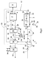
- a fuel cell system 1 which may preferably be arranged in a motor vehicle, comprises at least one fuel cell 2 and a reformer 3.
- the fuel cell 2 serves to generate electricity, which in a known manner consists of an oxidizing gas and a fuel gas generated.
- the fuel cell 2 may be formed, for example, as a solid-state fuel cell (SOFC) and preferably as a high-temperature fuel cell.
- SOFC solid-state fuel cell
- the fuel cell 2 is supplied on the cathode side with the oxidant gas, for example, by air or is formed by pure oxygen.
- the fuel cell 2 is supplied during operation on the anode side with the fuel gas, which is hydrogen-containing.
- the fuel cell 2 here has an anode input 4, an anode output 5, a cathode input 6, a cathode output 7 and at least one electrical connection or power connection 8.
- At least one electrical load 9 is connected or connectable to the fuel cell 2 or to the fuel cell system 1 via the at least one power connection 8.
- the electrical consumers 9 are preferably those which are not required for the normal driving operation of the vehicle. Rather, these consumers serve the driver to increase comfort when the vehicle is at rest, so when an internal combustion engine of the vehicle is turned off.
- the fuel cell system 1 thus provides an engine-independent power supply in the vehicle.
- Consumers 9 may be, for example, an air conditioner, a television, a refrigerator, a cooking area, a microwave oven and the fuel cell system 1 itself.
- the fuel cell system 1 may replace an alternator in vehicle operation, so that all electrical consumers of the vehicle then connected to the fuel cell 2 Consumers are 9.
- the reformer 3 is used to produce the hydrogen-containing fuel gas, which he in a known manner from Oxidatorgas, preferably Air or oxygen, and from fuel, preferably hydrocarbons generated.
- the fuel used to supply the reformer 3 is that fuel which is already available in the vehicle equipped with the fuel cell system 1 for supplying an internal combustion engine, for example, gasoline, diesel, natural gas.
- the reformer 3 includes a mixture forming section 10 and immediately adjacent thereto a catalyst section 11. In the mixture forming section 10, formation of a mixture of oxidizer gas and fuel occurs. At the same time, the mixture forming section 10 may also function as an evaporator when a liquid fuel is used. At the mixture forming section 10, a fuel inlet 12 and an oxidant inlet 13 of the reformer 3 are arranged. In the embodiments of FIGS. 1, 3 and 4, the reformer 3 also has a recirculation input 14.
- the catalyst section 11 serves to convert the mixture provided by the mixture forming section 10 into hydrogen-containing fuel gas.
- the catalyst section 11 comprises a catalyst 15 made of a suitable for producing such a fuel gas catalyst material, the z. B. is applied to a suitable substrate, such as ceramic or metal.
- a fuel gas outlet 16 of the reformer 3 is formed, which is connected via a fuel gas line 17 to the anode inlet 4.
- At least one oxidizer supply device 18 is provided which has, for example, a fuel cell oxidizer line 19 which is connected to the cathode inlet 6 and a reformer oxidizer line 20 which is connected to the oxidant inlet 13.
- the two oxidizer lines 19, 20 branch off from a common oxidizer supply line 22, in which a pump device 23 for driving the oxidizer gas to the fuel cell 2 or to the reformer 3 is arranged.
- the branching point 21 may be formed by a valve arrangement which controls the flow through one and / or through the other Oxidator ein 19, 20 or controls.
- two separate Oxidator fixturess wornen 18 may be provided, the reformer 3 and fuel cell 2 separately supplied with oxidizer gas.
- a fuel supply device 24 which has a fuel supply line 12 connected to the fuel supply line 25 and a pumping device 26 arranged therein.
- the fuel cell system 1 is also equipped with a residual gas burner 29, in which a combustion reaction takes place in order to burn residual fuel gas present in the anode exhaust with oxidant gas present in the cathode exhaust gas.
- the residual gas burner 29 has on the input side a cathode exhaust gas inlet 30 and an anode exhaust gas inlet 31. On the output side, the residual gas burner 29 has a burner exhaust gas outlet 32.
- the cathode exhaust gas line 27 is connected to the cathode exhaust gas inlet 30, while the anode exhaust gas line 28 is connected to the anode exhaust gas inlet 31.
- a burner exhaust pipe 33 is connected.
- the fuel cell system 1 may also be equipped with a heat exchanger 34, which is also referred to below as the main heat exchanger 34.
- the main heat exchanger 34 is on the one hand in the burner exhaust pipe 33 downstream of the residual gas burner 29 and on the other hand integrated into the fuel cell oxidizer 19. The main heat exchanger 34 thus enables a heat-transmitting coupling between the burner exhaust gas and the oxidant gas supplied to the fuel cell 2.
- the fuel cell system 1 can optionally be equipped with a further heat exchanger 35, which is also referred to below as an additional heat exchanger 35.
- the additional heat exchanger 35 is integrated on the one hand into the burner exhaust gas line 33 downstream of the main heat exchanger 34 and on the other hand into a waste heat path 36.
- the waste heat path 36 also serves to utilize heat contained in the burner exhaust gas.
- the waste heat path 36 through formed a coolant line of a coolant circuit of the internal combustion engine of the vehicle.
- the fuel cell system 1 can then be used, for example, as a heater for the internal combustion engine.
- the waste heat path 36 may be formed by a hot air pipe of an indoor heater of the vehicle.
- the fuel cell system 1 can then be used as auxiliary heater for the vehicle when a fan of the indoor heater forms one of the consumers 9.
- the fuel cell system 1 is also equipped with a recirculation line 37, which is connected on the input side via a connection point 38 to the anode exhaust gas line 28.
- the recirculation line 37 is connected in the embodiments of FIGS. 1, 3 and 4 via the Rezirkulationseingang 14 to the reformer 3 and in the embodiments of FIGS. 2 and 5 to 8 via a connection point 39 to the Reformeroxidator effet 20.
- the recirculation line 37 thus enables direct or indirect recycling of anode exhaust gas into the reformer 3.
- the fuel cell system 1 also has a conveyor 40, which serves to drive the anode exhaust gas.
- the conveyor 40 comprises a hot gas conveyor 41 which is adapted to be suitable for driving uncooled anode exhaust gas.
- the conveyor 40 through an exhaust gas turbocharger 42, which in the usual way a compressor 43 and a drive-coupled turbine 44 has.
- the compressor 43 of the exhaust gas turbocharger 42 forms the hot gas conveyor 41 of the conveyor 40.
- the turbine 44 is integrated into the burner exhaust gas line 33.
- the turbine 44 is integrated into the burner exhaust gas line 33 upstream of the main heat exchanger 34.
- the turbine 44 is integrated into the burner exhaust gas line 33 downstream of the main heat exchanger 34.
- FIG. 2 differs from the embodiment shown in FIG. 1 in that in the embodiment shown in FIG. 1 the recirculation line 37 is connected to the reformer 3 on the output side via the recirculation input 14, whereas in the embodiment according to FIG 2 is connected via the connection point 39 to the reformer oxidizer line 20. In the embodiment shown in Fig. 2 thus takes place within the reformer oxidizer 20 downstream of the junction 39, a mixture formation between oxidizer gas and anode exhaust gas.
- the recirculation line 37 is connected to the reformer 3 analogously to the embodiment according to FIG. Likewise, it is possible analogously to the embodiment of FIG. 2, here too connect the recirculation line 37 to the Reformeroxidator effet 20.
- the hot gas conveyor is incorporated into the recirculation line 37, while in the embodiment according to FIG. 6 it is integrated into the reformer oxygen duct 20 downstream of the connection point 39.
- a mixture of oxidant gas and anode exhaust gas is supplied to the compressor 43 on the suction side, which is colder than the uncooled anode exhaust gas in any case.
- the embodiment of FIG. 6 corresponds largely to a modification of the embodiment of FIG. 1. Analogous modifications are also possible to the embodiments of FIGS. 2 to 4 to pressurize the compressor 43 by admixing the reformer oxidizer gas with cooled anode exhaust gas.
- the exhaust-gas turbocharger 42 it is possible, in particular, to resort to a fresh-gas charging device of an internal combustion engine designed as an exhaust-gas turbocharger.
- This makes it possible to use existing and proven in practice exhaust gas turbocharger for driving the anode exhaust gas.
- an actually existing turbocharger which itself serves to charge an internal combustion engine, in the fuel cell system 1.
- a functional design can be adapted comparatively easily to the volume flow to be delivered.
- the respective exhaust gas turbocharger 42 can be used with its turbine. On In this way, for example, the embodiments shown in FIGS. 1 to 3 and 6 can be realized.
- the conveyor 40 comprises an electric drive 45 for driving the hot gas conveyor 41.
- the hot gas conveyor 41 can be used in principle again known per se Frischgaslade Nurs of internal combustion engines.
- the hot gas conveyor 43 can again be formed by a compressor of an exhaust gas turbocharger, which is used here without its turbine. The turbine is replaced by the electric drive 45.
- said charger 46 can be used as a hot gas conveyor 41.
- the recirculation line 37 is connected to the reformer 3 via the recirculation input 14.
- the hot gas conveyors 41 used in the embodiments of FIGS. 1 to 4 and 6 can thus basically be designed in the manner of a compressor 43, as is known per se from fresh gas charging devices of internal combustion engines.
- the invention is not limited to such embodiments limited, but should basically detect any suitable hot gas conveyor 41.
- the hot gas conveyor 41 is formed by a suction jet pump 47.
- the suction jet pump 47 has a Venturi tube 48 which defines an inlet 49, an outlet 50 and a side suction port 51 of the suction jet pump 47.
- the suction jet pump 47 is integrated into the reformer oxidizer line 20.
- the reformer oxidizer line 20 is connected to the inlet 49 and the outlet 50.
- the recirculation line 47 is connected on the output side to the suction port 51.
- the suction jet pump 47 can be particularly easily provided by using appropriate materials with the required hot gas resistance and can be realized particularly inexpensive.
- the recirculation line 37 is connected to the reformer oxidizer line 20 via the delivery device 40.
- the conveyor 40 is incorporated into the reformer oxidizer line 20. Furthermore, in these embodiments, the recirculation line 37 is connected upstream of the conveyor 40 via the connection point 39 to the reformer oxidizer line 20. In these embodiments, it comes in the reformer oxidizer 20 downstream of the junction 39 to a mixing between the anode exhaust gas and the reformer 3 supplied oxidizer gas. This leads to a cooling of the anode exhaust gas until the mixture on the suction side reaches the conveyor 40. Accordingly, it is fundamentally possible in this embodiment to design the conveyor 40 for comparatively low temperatures, so that overall it can be designed to be comparatively inexpensive.
- the embodiment shown in FIG. 8 differs from the embodiment shown in FIG. 7 in that, according to FIG.
- a recirculation heat exchanger 52 can be provided, which is integrated on the one hand in the recirculation unit 37 and on the other hand in the fuel cell oxidizer line 19.
- the recirculation heat exchanger 52 thereby realizes heat-transmitting coupling between the recycled anode exhaust gas and the oxidant gas supplied to the fuel cell 2, whereby the anode exhaust gas can be significantly cooled.
- the recirculation heat exchanger 52 is integrated into the fuel cell oxidizer line 19 upstream of the main heat exchanger 34.
- the fuel cell system 1 is also equipped with a thermally insulating insulation box 53, which is indicated here by a broken line. Within this isolation box 53, the particularly hot components of the fuel cell system 1 are arranged. In any case, inside the Isolation box 53, the fuel cell 2 and - if available - the residual gas burner 29 and the main heat exchanger 34 arranged.
- the conveyor 40 is also at least partially disposed within the insulation box 53.
- the electric drive 45 according to FIG. 4 may be arranged outside the insulation box 53.
- the reformer 3 may be disposed within the insulation box 53. In contrast, in the embodiments of FIGS.
- the conveyor 40 is disposed outside of the insulation box 53.
- the conveyor 40 requires only a comparatively low heat resistance, which makes it relatively inexpensive to implement.
- the reformer 3 may preferably be arranged outside the insulation box 53.
- the additional heat exchanger 35 and the respective consumer 9 are preferably arranged outside of the insulation box 53.
- the fuel cell system 1 may also include a sensor 54, which is formed in the present case by a plurality of temperature sensors 55, which are arranged at suitable measuring points.
- a temperature sensor 54 is located between the mixture formation section 10 and the catalyst section 11 of the reformer 11.
- a further temperature sensor 55 is arranged at the fuel gas outlet 16.
- a temperature sensor 55 may also be disposed at the burner exhaust port 32 or at the entrance of the main heat exchanger 34.
- a further temperature sensor 55 can also be arranged at the anode outlet 5.
Landscapes
- Life Sciences & Earth Sciences (AREA)
- Sustainable Development (AREA)
- Engineering & Computer Science (AREA)
- Manufacturing & Machinery (AREA)
- Sustainable Energy (AREA)
- Chemical & Material Sciences (AREA)
- Chemical Kinetics & Catalysis (AREA)
- Electrochemistry (AREA)
- General Chemical & Material Sciences (AREA)
- Fuel Cell (AREA)
- Electric Propulsion And Braking For Vehicles (AREA)
Applications Claiming Priority (1)
| Application Number | Priority Date | Filing Date | Title |
|---|---|---|---|
| DE102006021866A DE102006021866A1 (de) | 2006-05-09 | 2006-05-09 | Brennstoffzellensystem |
Publications (3)
| Publication Number | Publication Date |
|---|---|
| EP1855342A2 true EP1855342A2 (fr) | 2007-11-14 |
| EP1855342A3 EP1855342A3 (fr) | 2008-09-03 |
| EP1855342B1 EP1855342B1 (fr) | 2012-06-13 |
Family
ID=38320180
Family Applications (1)
| Application Number | Title | Priority Date | Filing Date |
|---|---|---|---|
| EP07106785A Active EP1855342B1 (fr) | 2006-05-09 | 2007-04-24 | système de pile à combustible |
Country Status (2)
| Country | Link |
|---|---|
| EP (1) | EP1855342B1 (fr) |
| DE (1) | DE102006021866A1 (fr) |
Cited By (7)
| Publication number | Priority date | Publication date | Assignee | Title |
|---|---|---|---|---|
| EP2003720A1 (fr) * | 2007-06-06 | 2008-12-17 | Bayerische Motoren Werke Aktiengesellschaft | Système de pile à combustible avec un réformateur |
| US20140255808A1 (en) * | 2013-03-08 | 2014-09-11 | Eberspächer Climate Control Systems GmbH & Co. KG | Fuel cell system |
| US20150104725A1 (en) * | 2012-06-04 | 2015-04-16 | Kyungdong Navien Co., Ltd. | Combined fuel cell and boiler system |
| DE102014215480A1 (de) | 2014-08-05 | 2016-02-11 | Avl Schrick Gmbh | Brennstoffzellensystem mit einer Fördereinrichtung für Anodenabgas |
| DE102014115096A1 (de) * | 2014-10-16 | 2016-04-21 | Eberspächer Climate Control Systems GmbH & Co. KG | System zur versorgung eines fahrzeugs mit elektrischer energie |
| US9614233B2 (en) | 2014-08-29 | 2017-04-04 | Honda Motor Co., Ltd. | Fuel cell module |
| US9698440B2 (en) | 2014-08-29 | 2017-07-04 | Honda Motor Co., Ltd. | Fuel cell module |
Families Citing this family (1)
| Publication number | Priority date | Publication date | Assignee | Title |
|---|---|---|---|---|
| DE102016215604A1 (de) * | 2016-08-19 | 2018-02-22 | Robert Bosch Gmbh | Brennstoffzellenvorrichtung |
Citations (6)
| Publication number | Priority date | Publication date | Assignee | Title |
|---|---|---|---|---|
| DE10315255A1 (de) | 2003-04-03 | 2004-10-21 | J. Eberspächer GmbH & Co. KG | Brennstoffzellensystem und Brenneranordnung für ein Brennstoffzellensystem |
| DE102004002337A1 (de) | 2004-01-16 | 2005-08-11 | Bayerische Motoren Werke Ag | Energieumwandlungsvorrichtung und Verfahren zum Betreiben der Energieumwandlungsvorrichtung |
| DE102005012230A1 (de) | 2004-03-24 | 2005-10-06 | General Electric Co. | Verfahren und System zum Anfahren und transienten Betrieb eines integrierten Brennstoffzellen-Gasturbinensystems |
| US20060003207A1 (en) | 2004-06-30 | 2006-01-05 | Chellappa Balan | Integrated power plant and system and method incorporating the same |
| DE102005001361A1 (de) | 2005-01-11 | 2006-07-20 | J. Eberspächer GmbH & Co. KG | Brennstoffzellensystem |
| EP1739777A2 (fr) | 2005-06-28 | 2007-01-03 | J. Eberspächer GmbH Co. KG | Système de pile à combustible pour véhicules |
Family Cites Families (6)
| Publication number | Priority date | Publication date | Assignee | Title |
|---|---|---|---|---|
| DE19856499C1 (de) * | 1998-12-08 | 2000-10-26 | Daimler Chrysler Ag | Verfahren und Vorrichtung zur zweistufigen Aufladung von Prozeßluft für eine Brennstoffzelle |
| DE19908905C2 (de) * | 1999-03-02 | 2003-03-20 | Daimler Chrysler Ag | Brennstoffzellensystem mit zugeordneter Wasserstofferzeugungsanlage |
| DE19928102B4 (de) * | 1999-06-19 | 2005-06-02 | Daimlerchrysler Ag | Fahrzeug mit einem Antriebs-Verbrennungsmotor und mit einem Brennstoffzellensystem zur Stromversorgung elektrischer Verbraucher des Fahrzeugs und Verfahren zum Betrieb eines derartigen Fahrzeugs |
| JP4048933B2 (ja) * | 2002-11-26 | 2008-02-20 | 株式会社デンソー | 燃料電池システム |
| DE10330123A1 (de) * | 2003-07-04 | 2005-01-20 | Volkswagen Ag | Brennstoffzellensystem und Verfahren zum Betrieb desselben |
| DE102006017615A1 (de) * | 2006-04-12 | 2007-10-18 | J. Eberspächer GmbH & Co. KG | Brennstoffzellensytem |
-
2006
- 2006-05-09 DE DE102006021866A patent/DE102006021866A1/de not_active Ceased
-
2007
- 2007-04-24 EP EP07106785A patent/EP1855342B1/fr active Active
Patent Citations (6)
| Publication number | Priority date | Publication date | Assignee | Title |
|---|---|---|---|---|
| DE10315255A1 (de) | 2003-04-03 | 2004-10-21 | J. Eberspächer GmbH & Co. KG | Brennstoffzellensystem und Brenneranordnung für ein Brennstoffzellensystem |
| DE102004002337A1 (de) | 2004-01-16 | 2005-08-11 | Bayerische Motoren Werke Ag | Energieumwandlungsvorrichtung und Verfahren zum Betreiben der Energieumwandlungsvorrichtung |
| DE102005012230A1 (de) | 2004-03-24 | 2005-10-06 | General Electric Co. | Verfahren und System zum Anfahren und transienten Betrieb eines integrierten Brennstoffzellen-Gasturbinensystems |
| US20060003207A1 (en) | 2004-06-30 | 2006-01-05 | Chellappa Balan | Integrated power plant and system and method incorporating the same |
| DE102005001361A1 (de) | 2005-01-11 | 2006-07-20 | J. Eberspächer GmbH & Co. KG | Brennstoffzellensystem |
| EP1739777A2 (fr) | 2005-06-28 | 2007-01-03 | J. Eberspächer GmbH Co. KG | Système de pile à combustible pour véhicules |
Cited By (10)
| Publication number | Priority date | Publication date | Assignee | Title |
|---|---|---|---|---|
| EP2003720A1 (fr) * | 2007-06-06 | 2008-12-17 | Bayerische Motoren Werke Aktiengesellschaft | Système de pile à combustible avec un réformateur |
| US20150104725A1 (en) * | 2012-06-04 | 2015-04-16 | Kyungdong Navien Co., Ltd. | Combined fuel cell and boiler system |
| US9917317B2 (en) * | 2012-06-04 | 2018-03-13 | Kyungdong Navien Co., Ltd. | Combined fuel cell and boiler system |
| US20140255808A1 (en) * | 2013-03-08 | 2014-09-11 | Eberspächer Climate Control Systems GmbH & Co. KG | Fuel cell system |
| US10193166B2 (en) * | 2013-03-08 | 2019-01-29 | Eberspächer Climate Control Systems GmbH & Co. KG | Fuel cell system |
| DE102014215480A1 (de) | 2014-08-05 | 2016-02-11 | Avl Schrick Gmbh | Brennstoffzellensystem mit einer Fördereinrichtung für Anodenabgas |
| US9614233B2 (en) | 2014-08-29 | 2017-04-04 | Honda Motor Co., Ltd. | Fuel cell module |
| US9698440B2 (en) | 2014-08-29 | 2017-07-04 | Honda Motor Co., Ltd. | Fuel cell module |
| DE102014115096A1 (de) * | 2014-10-16 | 2016-04-21 | Eberspächer Climate Control Systems GmbH & Co. KG | System zur versorgung eines fahrzeugs mit elektrischer energie |
| DE102014115096B4 (de) * | 2014-10-16 | 2021-01-14 | Eberspächer Climate Control Systems GmbH | System zur versorgung eines fahrzeugs mit elektrischer energie |
Also Published As
| Publication number | Publication date |
|---|---|
| DE102006021866A1 (de) | 2007-11-15 |
| EP1855342B1 (fr) | 2012-06-13 |
| EP1855342A3 (fr) | 2008-09-03 |
Similar Documents
| Publication | Publication Date | Title |
|---|---|---|
| EP1855342B1 (fr) | système de pile à combustible | |
| EP1845579B1 (fr) | Système de pile à combustible et procédé de fonctionnement correspondant | |
| DE102009060679B4 (de) | Betriebsverfahren für ein Brennstoffzellensystem | |
| DE102009030236B4 (de) | Brennstoffzellensystem und Betriebsverfahren | |
| EP1616361B1 (fr) | Dispositif de conversion de l'energie avec installation de reformage et installation de pile a combustible associees | |
| DE102011088563B4 (de) | Anordnung mit Brennstoffzellensystem | |
| EP1557896A1 (fr) | Système de conversion d'énergie et procédé de fonctionnement d'un dispositif de transformation d'énergie | |
| EP1906108A2 (fr) | Chauffage à hydrogène | |
| EP1845578B1 (fr) | Système de cellules combustibles | |
| EP1947723B1 (fr) | Système d'approvisionnement d'énergie | |
| EP1845576B1 (fr) | Système de cellules combustibles | |
| EP1844856B1 (fr) | Système de cellules combustibles et procédé de fonctionnement correspondant | |
| WO2008113327A2 (fr) | Système de pile à combustible à ligne de recirculation | |
| EP1845577B1 (fr) | Système de pile à combustible | |
| EP1942537B1 (fr) | Système de pile à combustible avec un dispositif de régénération pour un reformeur et son procédé | |
| DE102006023857B4 (de) | Brennstoffzellensystem und zugehöriges Betriebsverfahren | |
| EP1968150B1 (fr) | Système de piles à combustibles | |
| DE102009009667B4 (de) | Verfahren zum Betreiben eines Brennstoffzellensystems und Brennstoffzellensystem | |
| DE102007033151B4 (de) | Betriebsverfahren für ein Brennstoffzellensystem | |
| DE102008019942A1 (de) | Brennstoffzellensystem mit einem Nachbrenner | |
| DE102007040192A1 (de) | Reformer und Brennstoffzellensystem |
Legal Events
| Date | Code | Title | Description |
|---|---|---|---|
| PUAI | Public reference made under article 153(3) epc to a published international application that has entered the european phase |
Free format text: ORIGINAL CODE: 0009012 |
|
| AK | Designated contracting states |
Kind code of ref document: A2 Designated state(s): AT BE BG CH CY CZ DE DK EE ES FI FR GB GR HU IE IS IT LI LT LU LV MC MT NL PL PT RO SE SI SK TR |
|
| AX | Request for extension of the european patent |
Extension state: AL BA HR MK YU |
|
| PUAL | Search report despatched |
Free format text: ORIGINAL CODE: 0009013 |
|
| AK | Designated contracting states |
Kind code of ref document: A3 Designated state(s): AT BE BG CH CY CZ DE DK EE ES FI FR GB GR HU IE IS IT LI LT LU LV MC MT NL PL PT RO SE SI SK TR |
|
| AX | Request for extension of the european patent |
Extension state: AL BA HR MK RS |
|
| RIC1 | Information provided on ipc code assigned before grant |
Ipc: B60L 11/00 20060101ALI20080731BHEP Ipc: H01M 8/04 20060101AFI20070809BHEP Ipc: H01M 8/12 20060101ALN20080731BHEP Ipc: H01M 8/06 20060101ALN20080731BHEP |
|
| 17P | Request for examination filed |
Effective date: 20090303 |
|
| 17Q | First examination report despatched |
Effective date: 20090331 |
|
| AKX | Designation fees paid |
Designated state(s): CZ DE FR GB NL SE |
|
| GRAP | Despatch of communication of intention to grant a patent |
Free format text: ORIGINAL CODE: EPIDOSNIGR1 |
|
| GRAS | Grant fee paid |
Free format text: ORIGINAL CODE: EPIDOSNIGR3 |
|
| GRAA | (expected) grant |
Free format text: ORIGINAL CODE: 0009210 |
|
| AK | Designated contracting states |
Kind code of ref document: B1 Designated state(s): CZ DE FR GB NL SE |
|
| REG | Reference to a national code |
Ref country code: GB Ref legal event code: FG4D Free format text: NOT ENGLISH |
|
| REG | Reference to a national code |
Ref country code: DE Ref legal event code: R096 Ref document number: 502007010033 Country of ref document: DE Effective date: 20120809 |
|
| REG | Reference to a national code |
Ref country code: NL Ref legal event code: T3 |
|
| REG | Reference to a national code |
Ref country code: SE Ref legal event code: TRGR |
|
| PLBE | No opposition filed within time limit |
Free format text: ORIGINAL CODE: 0009261 |
|
| STAA | Information on the status of an ep patent application or granted ep patent |
Free format text: STATUS: NO OPPOSITION FILED WITHIN TIME LIMIT |
|
| 26N | No opposition filed |
Effective date: 20130314 |
|
| REG | Reference to a national code |
Ref country code: DE Ref legal event code: R097 Ref document number: 502007010033 Country of ref document: DE Effective date: 20130314 |
|
| PGFP | Annual fee paid to national office [announced via postgrant information from national office to epo] |
Ref country code: FR Payment date: 20130523 Year of fee payment: 7 Ref country code: NL Payment date: 20130422 Year of fee payment: 7 |
|
| REG | Reference to a national code |
Ref country code: NL Ref legal event code: TD Effective date: 20131004 |
|
| REG | Reference to a national code |
Ref country code: FR Ref legal event code: CD Owner name: EBERSPACHER CLIMATE CONTROL SYSTEMS GMBH & CO. KG Effective date: 20131129 |
|
| REG | Reference to a national code |
Ref country code: DE Ref legal event code: R082 Ref document number: 502007010033 Country of ref document: DE Representative=s name: BRP RENAUD UND PARTNER MBB RECHTSANWAELTE PATE, DE Effective date: 20131212 Ref country code: DE Ref legal event code: R082 Ref document number: 502007010033 Country of ref document: DE Representative=s name: BRP RENAUD UND PARTNER MBB, DE Effective date: 20131212 Ref country code: DE Ref legal event code: R081 Ref document number: 502007010033 Country of ref document: DE Owner name: EBERSPAECHER CLIMATE CONTROL SYSTEMS GMBH & CO, DE Free format text: FORMER OWNER: J. EBERSPAECHER GMBH & CO. KG, 73730 ESSLINGEN, DE Effective date: 20131212 Ref country code: DE Ref legal event code: R082 Ref document number: 502007010033 Country of ref document: DE Representative=s name: BRP RENAUD & PARTNER, DE Effective date: 20131212 Ref country code: DE Ref legal event code: R081 Ref document number: 502007010033 Country of ref document: DE Owner name: EBERSPAECHER CLIMATE CONTROL SYSTEMS GMBH & CO, DE Free format text: FORMER OWNER: J. EBERSPAECHER GMBH & CO. KG, 73730 ESSLINGEN, DE Effective date: 20120618 |
|
| REG | Reference to a national code |
Ref country code: FR Ref legal event code: TP Owner name: EBERSPACHER EXHAUST TECHNOLOGY GMBH & CO. KG, DE Effective date: 20140204 |
|
| PGFP | Annual fee paid to national office [announced via postgrant information from national office to epo] |
Ref country code: GB Payment date: 20140423 Year of fee payment: 8 |
|
| PGFP | Annual fee paid to national office [announced via postgrant information from national office to epo] |
Ref country code: CZ Payment date: 20140416 Year of fee payment: 8 |
|
| REG | Reference to a national code |
Ref country code: NL Ref legal event code: V1 Effective date: 20141101 |
|
| REG | Reference to a national code |
Ref country code: FR Ref legal event code: ST Effective date: 20141231 |
|
| PG25 | Lapsed in a contracting state [announced via postgrant information from national office to epo] |
Ref country code: FR Free format text: LAPSE BECAUSE OF NON-PAYMENT OF DUE FEES Effective date: 20140430 Ref country code: NL Free format text: LAPSE BECAUSE OF NON-PAYMENT OF DUE FEES Effective date: 20141101 |
|
| GBPC | Gb: european patent ceased through non-payment of renewal fee |
Effective date: 20150424 |
|
| PG25 | Lapsed in a contracting state [announced via postgrant information from national office to epo] |
Ref country code: GB Free format text: LAPSE BECAUSE OF NON-PAYMENT OF DUE FEES Effective date: 20150424 |
|
| PG25 | Lapsed in a contracting state [announced via postgrant information from national office to epo] |
Ref country code: CZ Free format text: LAPSE BECAUSE OF NON-PAYMENT OF DUE FEES Effective date: 20150424 |
|
| PGFP | Annual fee paid to national office [announced via postgrant information from national office to epo] |
Ref country code: DE Payment date: 20240430 Year of fee payment: 18 |
|
| PGFP | Annual fee paid to national office [announced via postgrant information from national office to epo] |
Ref country code: SE Payment date: 20250423 Year of fee payment: 19 |
|
| REG | Reference to a national code |
Ref country code: DE Ref legal event code: R119 Ref document number: 502007010033 Country of ref document: DE |
|
| PG25 | Lapsed in a contracting state [announced via postgrant information from national office to epo] |
Ref country code: DE Free format text: LAPSE BECAUSE OF NON-PAYMENT OF DUE FEES Effective date: 20251104 |