EP1855356B1 - Appareil de connexion pour câbles multiconducteur - Google Patents
Appareil de connexion pour câbles multiconducteur Download PDFInfo
- Publication number
- EP1855356B1 EP1855356B1 EP07105048A EP07105048A EP1855356B1 EP 1855356 B1 EP1855356 B1 EP 1855356B1 EP 07105048 A EP07105048 A EP 07105048A EP 07105048 A EP07105048 A EP 07105048A EP 1855356 B1 EP1855356 B1 EP 1855356B1
- Authority
- EP
- European Patent Office
- Prior art keywords
- connecting device
- insulation
- contacts
- flat ribbon
- ribbon cable
- Prior art date
- Legal status (The legal status is an assumption and is not a legal conclusion. Google has not performed a legal analysis and makes no representation as to the accuracy of the status listed.)
- Active
Links
Images



Classifications
-
- H—ELECTRICITY
- H01—ELECTRIC ELEMENTS
- H01R—ELECTRICALLY-CONDUCTIVE CONNECTIONS; STRUCTURAL ASSOCIATIONS OF A PLURALITY OF MUTUALLY-INSULATED ELECTRICAL CONNECTING ELEMENTS; COUPLING DEVICES; CURRENT COLLECTORS
- H01R12/00—Structural associations of a plurality of mutually-insulated electrical connecting elements, specially adapted for printed circuits, e.g. printed circuit boards [PCB], flat or ribbon cables, or like generally planar structures, e.g. terminal strips, terminal blocks; Coupling devices specially adapted for printed circuits, flat or ribbon cables, or like generally planar structures; Terminals specially adapted for contact with, or insertion into, printed circuits, flat or ribbon cables, or like generally planar structures
- H01R12/70—Coupling devices
- H01R12/77—Coupling devices for flexible printed circuits, flat or ribbon cables or like structures
- H01R12/771—Details
- H01R12/772—Strain relieving means
-
- H—ELECTRICITY
- H01—ELECTRIC ELEMENTS
- H01R—ELECTRICALLY-CONDUCTIVE CONNECTIONS; STRUCTURAL ASSOCIATIONS OF A PLURALITY OF MUTUALLY-INSULATED ELECTRICAL CONNECTING ELEMENTS; COUPLING DEVICES; CURRENT COLLECTORS
- H01R12/00—Structural associations of a plurality of mutually-insulated electrical connecting elements, specially adapted for printed circuits, e.g. printed circuit boards [PCB], flat or ribbon cables, or like generally planar structures, e.g. terminal strips, terminal blocks; Coupling devices specially adapted for printed circuits, flat or ribbon cables, or like generally planar structures; Terminals specially adapted for contact with, or insertion into, printed circuits, flat or ribbon cables, or like generally planar structures
- H01R12/50—Fixed connections
- H01R12/59—Fixed connections for flexible printed circuits, flat or ribbon cables or like structures
- H01R12/65—Fixed connections for flexible printed circuits, flat or ribbon cables or like structures characterised by the terminal
- H01R12/67—Fixed connections for flexible printed circuits, flat or ribbon cables or like structures characterised by the terminal insulation penetrating terminals
-
- H—ELECTRICITY
- H01—ELECTRIC ELEMENTS
- H01R—ELECTRICALLY-CONDUCTIVE CONNECTIONS; STRUCTURAL ASSOCIATIONS OF A PLURALITY OF MUTUALLY-INSULATED ELECTRICAL CONNECTING ELEMENTS; COUPLING DEVICES; CURRENT COLLECTORS
- H01R4/00—Electrically-conductive connections between two or more conductive members in direct contact, i.e. touching one another; Means for effecting or maintaining such contact; Electrically-conductive connections having two or more spaced connecting locations for conductors and using contact members penetrating insulation
- H01R4/24—Connections using contact members penetrating or cutting insulation or cable strands
- H01R4/2404—Connections using contact members penetrating or cutting insulation or cable strands the contact members having teeth, prongs, pins or needles penetrating the insulation
- H01R4/2412—Connections using contact members penetrating or cutting insulation or cable strands the contact members having teeth, prongs, pins or needles penetrating the insulation actuated by insulated cams or wedges
Definitions
- the invention relates to a connection device according to the preamble of claim 1.
- connection devices - even with insulation-penetrating contacts - are known per se, so from the DE 34 22 607 C2 and the generic DE 44 02 837 A1 ,
- connection devices for the ends of flat cables reveal the US 5,429,526 , the DE 44 36 829 A1 discloses a connection device according to the preamble of claim 1, the DE 92 10 333 U1 , the US 4,252,396 and the US 5,076,801 ,
- At least one of the wedge arrangements is designed for connecting the ribbon cable, in particular such that it is designed for sliding the flat cable onto the insulation-penetrating contacts, preferably until contacting the conductors and / or pushing the insulation-penetrating contacts onto the ribbon cable.
- At least one or more of the wedge assemblies are further configured to activate a cable strain relief device.
- the advantageous wedge actuation technique is also used for the task of strain relief. This preferably occurs in such a way that the wedge arrangements for strain relief each have a wedge surface on the inside of the sliding cover, on which a respective web slides for strain relief during the wiring.
- the wedge assemblies for wiring and strain relief are coordinated so that the strain relief is activated only after the connection of the ribbon cable.
- a screwdriver is used for contacting, which is adapted to perform the relative displacement of the wedges of the wedge assembly with a high leverage.
- the wedges of the wedge arrangement are configured such that the flat cable is possibly pressed together with other elements (as described below) on the insulation-penetrating contacts.
- the housing is constructed in several parts and has a base portion and a lid portion, which in turn are preferably designed in several parts. It is possible to make all parts of the base portion and the Deckelab-section substantially plate-like, so that the entire housing is relatively flat.
- a sliding cover is preferably provided, which is displaceably guided on a base plate and having on its inside wedges which cooperate with wedges of a support plate, wherein the support plate is pressed together with the cable and a receiving plate for the cable as a unit on the insulation piercing contacts ,
- This version is compact and still realizes a particularly safe wiring.
- Fig. 1 shows an explosive view of a connection device 1, which is designed for contacting a flat cable 2, which usually has a plurality of conductors 3, which may each be surrounded by an insulation and embedded in a higher cable sheath 4.
- the flat cable may for example be a flat cable that is laid in a lift shaft.
- the connecting device has a multi-part housing 5, which comprises a base portion 6 and a cover portion 7, which in turn are each preferably formed in several parts.
- the base portion 6 a base plate 8, on which a plurality of insulation piercing contacts is arranged, which are here designed as Piercingfulnesse 9, but which may also be formed as a cutting contacts.
- a plurality of PiercingANDen 9 are arranged, which here in each case preferably each other angled aligned, crossed double points 10, 11 (see Fig. 5b ), which can be provided in addition to increase the insulation penetrating effect with cutting edges to ensure a particularly secure contact of the individual wires of the flat cable to be contacted.
- the base plate 8 has two mutually parallel side webs 12, 13, which realize a guide for a later explained in more detail holding plate 18.
- the side bars are higher than the flat cable 2, so that they project laterally beyond the edge of the inserted flat cable 2.
- the isolations pleadringenden contacts 9 are preferably connected to the realization of a T-type branch on the flat cable 2 to other terminals, which are formed here, for example, as a particularly fast and easy contactable direct plug spring contacts 14 (see also Fig. 5b ), which could also be designed as tension spring contacts, also as IDC contacts as screw contacts or in any other way (not shown).
- the insulation piercing contacts 9 protrude from the base plate 8 toward the flat cable 2 side with their tips 10, 11.
- the insulation-piercing contacts together with the direct plug contacts 14 are respectively inserted in receiving chambers 15 in the base plate 8, which are designed so open to the side of the flat cable 2, that the insulation-penetrating contacts 9 in the assembly of this page in the Receiving chambers 15 are used.
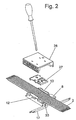
- the receiving chambers 15 may be provided with further openings which are configured such that branch conductor 17th (please refer Fig. 2 ; possibly also combined as a flat cable) and / or actuating tools (opening 16, Fig. 5 )) can be inserted to actuate the branch contacts in the receiving chambers 15, wherein the openings 16 are further designed so that the insulation piercing contacts (in particular piercing contacts) 9 can not be made from the on take-combs 15.
- clearances 33 are provided here on the side facing away from the flat cable 2 side of the base plate.
- the receiving chambers 15 and the insulation-penetrating contacts for the different conductors of the flat cable 2 to be contacted may be arranged slightly offset in the direction of the longitudinal extent of the flat cable 2, so that the individual IDC contacts may also be slightly wider than the distance of the conductors of the flat cable 2.
- eleven piercing contacts 9 are accommodated in a small space here.
- the receiving chambers 15 are covered by a cross-holding plate 18, which first latching means (here latching webs 19) may be latched with corresponding second latching means (here latching recesses 20) of the base plate.
- first latching means here latching webs 19
- second latching means here latching recesses 20
- the holding plate 18 is provided with openings, in particular slots 21, from which protrude the insulation piercing contacts in the direction of the flat cable 2 to be inserted.
- an optional receiving plate 22 for receiving the flat cable can be placed, which preferably has a contouring 23, which corresponds to the contour of the shell of the flat cable to be contacted so that it is well aligned and centered in the contouring 23, which is safe Contacting is an advantage.
- the receiving plate 22 has here first locking means (here again latching webs 24), which allows a latching to corresponding latching means (here again latching recesses 25) of the base plate 8.
- the receiving plate 22 is in turn provided with openings, in particular slots 26, from which protrude the insulation-penetrating contacts 9 in the contacted state.
- the receiving plate 22 In the non-contacted state, the receiving plate 22 is still so high on the base plate 8, that the insulation piercing contacts 9 do not protrude from it, so that the flat cable can be placed.
- the receiving plate 22 is displaceable perpendicular to the flat cable to the base plate 8 for contacting.
- the holding plate 18 and the receiving plate 22 could also be integrally formed (not shown here).
- the actual contacting of the flat cable is then carried out with the aid of the lid portion 7, which also serves as an actuating unit and which is guided displaceably relative to the base portion.
- This actuating unit consists of a support plate 27 which can be placed on the base section receiving the flat cable 2 and a sliding cover 28.
- the support plate 27 has a contour - here lateral webs 29 - which cooperates with the contour - in particular the side bars 12, 13 - of the base portion such that the support plate 27 in the mounted state before the wiring, although perpendicular to the flat cable 2 in the direction of isolations sacrifices 9 is movable, but not or substantially not in a direction parallel to the extension of the flat cable. 2
- the sliding cover 28 on side webs 31 which engage the base plate 8 at webs 40 directly on their sides ( Fig. 8 ) or which cooperate with the base plate 8 in the manner of a tongue and groove arrangement.
- the sliding cover 28 is slidably guided in the longitudinal direction of the flat cable at the base portion (Siege Fig. 2-7 ).
- Wedge elements 32, 34 of the first wedge assembly 30 are designed such that when sliding the sliding cover 28 on the base plate parallel to the flat cable 2, the support plate 27 presses with the flat cable 2 and the receiving plate 22 perpendicular to the flat cable 2 on the insulation-penetrating contacts 9, what leads that the insulation piercing contacts 9 first penetrate / pierce the receiving plate and then the cable sheath 4 and the conductor insulations and contact the individual conductors 3.
- the wedge elements 32, 34 come here below the sliding cover 28 to the plant ( Fig. 6 ).
- the wedge elements 32, 34 may have a constant inclination angle ⁇ to the flat cable 2.
- the inclination or wedge angle ⁇ could, however, also be variable in the longitudinal direction of the flat cable 2 (not shown here).
- At least one web (s) 35 extending transversely to the flat cable 2 is or are formed on the support plate 27, which, after contacting, rotates the screwdriver further (FIG. Fig. 7 ) between the sliding cover 28 and the flat cable 2 is jammed, so that the flat cable 2 is securely clamped in the manner of a strain relief between the support plate 27 and the base portion 6 of the housing 5.
- wedge assemblies 36, 37 each provided with a wedge surface on the inside of the sliding cover 28, on which each one of the webs 35 slides along, wherein the wedge assemblies 30, 36, 37 are coordinated such that the strain relief is activated after connecting the ribbon cable.
- the process of wiring is in Fig. 2 to 4 and 5 to 7 shown.
- the wiring is preferably carried out by means of a screwdriver which can be used in a recess 36 of the sliding cover 28 and with its tip on the base plate can be supported (see also Fig. 8 ) and with the preferably quickly and easily by means of a single pivoting movement, the wiring of the flat cable 2 can be done.
- a screwdriver which can be used in a recess 36 of the sliding cover 28 and with its tip on the base plate can be supported (see also Fig. 8 ) and with the preferably quickly and easily by means of a single pivoting movement, the wiring of the flat cable 2 can be done.
- To produce a branch on the continuous flat cable 2 then only the branch conductor 17 are to be connected.
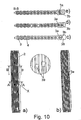
- FIG. 9 and 10 are in Fig. 9 and 10 shown.
- the flat cable 2 of Fig. 9 corresponds to the Fig. 1 , This differs from the coded ribbon cable of Fig. 10 in that in each case two of the conductors 3a, 3b in any case sections (at least up to the area to be connected) in so-called twisted pair technology are twisted together, which from the sections and front views of Fig. 10c, d, e becomes clear.
- the twisted together conductors 3a, 3b are arranged in a widened coding region 38 of the cable sheath, which is designed like a coding and thus always allows a correct wiring of this cable.
- this coded ribbon cable sections (section area 39) is severed to switch here an electronics between the two severed ends. Accordingly, several piercing contacts 9 for contacting the two ends of these conductors are provided for these conductors.
Landscapes
- Multi-Conductor Connections (AREA)
- Coupling Device And Connection With Printed Circuit (AREA)
- Insulated Conductors (AREA)
- Communication Cables (AREA)
- Connections By Means Of Piercing Elements, Nuts, Or Screws (AREA)
Claims (34)
- Dispositif de raccordement pour la mise en contact de conducteurs d'un câble, qui présente plusieurs conducteurs (3), en particulier de conducteurs d'un câble plat (2) continu, les conducteurs étant entourés éventuellement à chaque fois d'une isolation et étant insérés dans une gaine de câble (4) placée au-dessus, présentant les caractéristiques suivantes :a. un boîtier (5) en plusieurs parties, qui comprend une partie de base (6) pour le logement du câble (2) et une partie de couvercle (7),b. des contacts, en particulier des contacts perforants (9), disposés sur/dans le boîtier (5) et pénétrant l'isolation, etc. au moins un ou plusieurs agencement(s) de clavette (30, 36, 37),
caractérisé en ce qued. au moins l'un des agencements de clavette (30) est conçu pour le câblage du câble plat. - Dispositif de raccordement selon la revendication 1, caractérisé en ce que le au moins un des agencements de clavette (30) pour le câblage du câble plat est conçu pour glisser le câble plat sur les contacts (9) pénétrant l'isolation, de préférence jusqu'à la mise en contact des conducteurs et/ou pour glisser les contacts (9) pénétrant l'isolation sur le câble plat.
- Dispositif de raccordement selon la revendication 1, 2 ou 3, caractérisé en ce qu'au moins un ou plusieurs des agencements de clavette (36, 37) est/sont conçu(s) pour activer un dispositif pour la décharge de traction du câble.
- Dispositif de raccordement selon au moins l'une quelconque des revendications précédentes, caractérisé en ce que les agencements de clavette pour le câblage et pour la décharge de traction sont adaptés les uns aux autres, de telle sorte que la décharge de traction n'est activée qu'après le câblage du câble plat.
- Dispositif de raccordement selon la revendication 1, caractérisé en ce que la partie de couvercle (7) peut être déplacée tout ou partiellement par rapport à la partie de base (6).
- Dispositif de raccordement selon au moins l'une quelconque des revendications précédentes, caractérisé en ce que les agencements de clavette (36, 37) pour la décharge de traction présentent à chaque fois une surface de clavette sur le côté intérieur du couvercle coulissant (28), sur laquelle, lors du câblage, une nervure (35) glisse le long de la plaque de soutien (27) pour la décharge de traction.
- Dispositif de raccordement selon l'une quelconque des revendications précédentes, caractérisé en ce que la partie de base (6) présente une plaque de base (8) sur laquelle est disposée une pluralité de contacts pénétrant l'isolation.
- Dispositif de raccordement selon l'une quelconque des revendications précédentes, caractérisé en ce que la plaque de base (8) présente des nervures latérales (12, 13) entre lesquelles le câble plat (2) à mettre en contact peut être inséré.
- Dispositif de raccordement selon l'une quelconque des revendications précédentes, caractérisé en ce que les contacts (9) pénétrant l'isolation sont reliés à d'autres branchements pour réaliser une dérivation sur le câble plat (2).
- Dispositif de raccordement selon l'une quelconque des revendications précédentes, caractérisé en ce que les autres branchements sont conçus sous forme de contacts à ressort de pression et à emboîtement direct (14).
- Dispositif de raccordement selon l'une quelconque des revendications précédentes, caractérisé en ce que les contacts pénétrant l'isolation sont placés avec les contacts à emboîtement direct (14) dans des chambres de logement (15) dans la plaque de base (8).
- Dispositif de raccordement selon l'une quelconque des revendications précédentes, caractérisé en ce que les chambres de logement (15) sont conçues ouvertes en direction du côté du câble plat (2).
- Dispositif de raccordement selon l'une quelconque des revendications précédentes, caractérisé en ce que les chambres de logement (15) et les contacts (9) pénétrant l'isolation sont disposés de façon décalée entre eux en direction de l'extension longitudinale du câble plat (2).
- Dispositif de raccordement selon l'une quelconque des revendications précédentes, caractérisé en ce que les chambres de logement (15) sont recouvertes par une plaque de retenue (18) en recouvrement.
- Dispositif de raccordement selon l'une quelconque des revendications précédentes, caractérisé en ce que la plaque de retenue (18) présente des moyens de blocage (19), qui peuvent être encliquetés sur des moyens de blocage (évidements de blocage 20) correspondants sur la plaque de base.
- Dispositif de raccordement selon l'une quelconque des revendications précédentes, caractérisé en ce que la plaque de retenue (18) est dotée de percements, en particulier de fentes (21), par lesquels les contacts pénétrant l'isolation dépassent en direction du câble plat (2) à introduire.
- Dispositif de raccordement selon l'une quelconque des revendications précédentes, caractérisé en ce qu'une plaque de logement (22) peut être posée sur la plaque de retenue (18).
- Dispositif de raccordement selon l'une quelconque des revendications précédentes, caractérisé en ce que la plaque de logement (22) présente un contour (23) qui correspond à un contour du câble plat (2).
- Dispositif de raccordement selon l'une quelconque des revendications précédentes, caractérisé en ce que la plaque de logement (22) présente des premiers moyens de blocage, en particulier des nervures de blocage (24), qui permettent un enclenchement sur des moyens de blocage appropriés, en particulier des évidements de blocage (25).
- Dispositif de raccordement selon l'une quelconque des revendications précédentes, caractérisé en ce que la plaque de logement (22) est dotée d'autres percements, en particulier de fentes (26).
- Dispositif de raccordement selon l'une quelconque des revendications précédentes, caractérisé en ce que la plaque de logement (22) peut être posée dans l'état non encore contacté à un niveau élevé sur la plaque de base (8), de telle sorte que les contacts (9) pénétrant l'isolation ne dépassent pas de la plaque.
- Dispositif de raccordement selon l'une quelconque des revendications précédentes, caractérisé en ce que la partie de couvercle est conçue comme unité d'actionnement, qui présente une plaque de soutien (27) et un couvercle coulissant (28).
- Dispositif de raccordement selon l'une quelconque des revendications précédentes, caractérisé en ce que le couvercle coulissant (28) est guidé de façon coulissante sur la plaque de base (8).
- Dispositif de raccordement selon l'une quelconque des revendications précédentes, caractérisé en ce que la plaque de soutien (27) présente un contour qui coopère avec le contour de la partie de base, de telle sorte que la plaque de soutien (27) est mobile dans l'état monté, avant le câblage, perpendiculairement au câble plat (2) en direction des contacts (9) pénétrant l'isolation, mais pour l'essentiel pas dans une direction parallèle à l'extension du câble plat (2).
- Dispositif de raccordement selon l'une quelconque des revendications précédentes, caractérisé en ce que la plaque de soutien (27) est dotée d'évidements et/ou de percements (30) pour les contacts (9) pénétrant l'isolation.
- Dispositif de raccordement selon l'une quelconque des revendications précédentes, caractérisé en ce que le couvercle coulissant (28) présente des nervures latérales (31), qui saisissent par-dessous la plaque de base (8) sur ses côtés.
- Dispositif de raccordement selon l'une quelconque des revendications précédentes, caractérisé en ce qu'au moins un ou de préférence plusieurs éléments de clavette ou contours de clavette (32, 34) sont formés entre le couvercle coulissant (28) et/ou la plaque de soutien (27) pour réaliser l'agencement de clavette.
- Dispositif de raccordement selon l'une quelconque des revendications précédentes, caractérisé en ce que les éléments de clavette (32, 34) sont conçus de telle sorte que, lorsqu'on fait glisser le couvercle coulissant (28) sur la plaque de base (8) parallèlement au câble plat (2), le couvercle coulissant appuie la plaque de soutien (27) avec le câble plat (2) et éventuellement la plaque de logement (22) perpendiculairement au câble plat (2) sur les contacts (9) pénétrant l'isolation, de sorte que les contacts (9) pénétrant l'isolation pénètrent/perforent d'abord la plaque de logement et ensuite la gaine de câble (4) et les isolations de conducteur et établissent un contact avec les conducteurs (3) individuels.
- Dispositif de raccordement selon l'une quelconque des revendications précédentes, caractérisé en ce que les éléments de clavette présentent un angle d'inclinaison (α) constant par rapport au câble plat (2).
- Dispositif de raccordement selon l'une quelconque des revendications précédentes, caractérisé en ce que les éléments de clavette (32, 34) sont conçus de telle sorte que, lors du coulissement du couvercle coulissant (28), la plaque de soutien (27) et les contacts (9) pénétrant l'isolation sont déplacés les uns vers les autres, de sorte que les contacts (9) pénétrant l'isolation établissent un contact avec le câble plat (2).
- Dispositif de raccordement selon l'une quelconque des revendications précédentes, caractérisé en ce que la nervure (35), s'étendant transversalement au câble plat (2), du dispositif de décharge de traction, qui est coincée après la mise en contact entre le couvercle coulissant (28) et le câble plat (2) à la façon d'une décharge de traction sur le câble plat (2), est formée sur la plaque de soutien (27).
- Dispositif de raccordement selon l'une quelconque des revendications précédentes, caractérisé en ce que les contacts (9) pénétrant l'isolation présentent à chaque fois des doubles pointes (10, 11).
- Dispositif de raccordement selon l'une quelconque des revendications précédentes, caractérisé en ce que, dans l'état câblé, à chaque fois un ou plusieurs des conducteurs du câble plat codé sont séparés par endroits (zone de découpe 39) et en ce que plusieurs des contacts (9) pénétrant l'isolation sont prévus pour ces conducteurs pour la mise en contact des deux extrémités de ces conducteurs.
- Dispositif de raccordement selon l'une quelconque des revendications précédentes, caractérisé en ce que le câble est un câble plat (2), qui présente deux conducteurs (3a, 3b) extérieurs, qui sont torsadés les uns avec les autres dans la technique à paires torsadées ("twisted pair"), les conducteurs (3a, 3b) torsadés les uns avec les autres étant disposés dans une zone de codage (38) élargie de la gaine de câble.
Applications Claiming Priority (1)
| Application Number | Priority Date | Filing Date | Title |
|---|---|---|---|
| DE202006007510U DE202006007510U1 (de) | 2006-05-11 | 2006-05-11 | Anschlussvorrichtung für Mehrleiterkabel |
Publications (2)
| Publication Number | Publication Date |
|---|---|
| EP1855356A1 EP1855356A1 (fr) | 2007-11-14 |
| EP1855356B1 true EP1855356B1 (fr) | 2011-01-26 |
Family
ID=38196953
Family Applications (1)
| Application Number | Title | Priority Date | Filing Date |
|---|---|---|---|
| EP07105048A Active EP1855356B1 (fr) | 2006-05-11 | 2007-03-27 | Appareil de connexion pour câbles multiconducteur |
Country Status (6)
| Country | Link |
|---|---|
| US (1) | US7347716B2 (fr) |
| EP (1) | EP1855356B1 (fr) |
| JP (1) | JP4838755B2 (fr) |
| AT (1) | ATE497271T1 (fr) |
| DE (2) | DE202006007510U1 (fr) |
| ES (1) | ES2360372T3 (fr) |
Families Citing this family (19)
| Publication number | Priority date | Publication date | Assignee | Title |
|---|---|---|---|---|
| US7382774B2 (en) * | 2005-05-31 | 2008-06-03 | Falco Anthony R | Bankover connection system |
| JP4579949B2 (ja) * | 2007-07-24 | 2010-11-10 | 古河電気工業株式会社 | 接続端子の接続構造及び接続方法 |
| DE202008008696U1 (de) | 2008-06-28 | 2009-11-19 | Weidmüller Interface GmbH & Co. KG | Anschlussvorrichtung für Mehrleiterkabel |
| US7845968B1 (en) | 2010-01-12 | 2010-12-07 | Phoenix Contact Development & Manufacturing, Inc. | Electrical connector assembly and method |
| US8887655B2 (en) | 2012-01-25 | 2014-11-18 | Honeywell International Inc. | Valve actuator with position indicator extension |
| DE202012101070U1 (de) * | 2012-03-26 | 2013-06-27 | Zumtobel Lighting Gmbh | Stanzwerkzeug für Flachbandkabel |
| US9664409B2 (en) | 2012-06-14 | 2017-05-30 | Honeywell International Inc. | HVAC damper system |
| US10302207B2 (en) | 2012-06-14 | 2019-05-28 | Honeywell International Inc. | Spring loaded HVAC damper |
| US10119721B2 (en) | 2012-06-14 | 2018-11-06 | Honeywell International Inc. | Standoff for use with an insulated HVAC duct |
| DE102013002740A1 (de) * | 2013-02-19 | 2014-08-21 | Wieland Electric Gmbh | Flachkabel mit gerillter und planter Oberfläche |
| US9623523B2 (en) | 2013-12-18 | 2017-04-18 | Honeywell International Inc. | HVAC actuator with taping flange |
| US9732980B2 (en) | 2013-12-18 | 2017-08-15 | Honeywell International Inc. | HVAC actuator with range adjustment |
| US10941960B2 (en) | 2013-12-18 | 2021-03-09 | Ademco Inc. | HVAC actuator with position indicator |
| US9423143B2 (en) | 2013-12-18 | 2016-08-23 | Honeywell International Inc. | HVAC actuator with light indicator |
| US9568207B2 (en) | 2013-12-18 | 2017-02-14 | Honeywell International Inc. | HVAC actuator with removable wire blocking tab |
| USD728071S1 (en) | 2013-12-27 | 2015-04-28 | Honeywell International Inc. | HVAC actuator |
| JP6370463B1 (ja) * | 2017-11-27 | 2018-08-08 | 株式会社ダイカン | ダクトレール用電源ユニット |
| US10186789B1 (en) | 2018-04-13 | 2019-01-22 | Rustcraft Industries LLC | Keyed cable and connector system |
| SE542669C2 (en) | 2018-12-21 | 2020-06-23 | Ind Robi Ab | Cable connector arranged to pierce an electrical cable |
Family Cites Families (19)
| Publication number | Priority date | Publication date | Assignee | Title |
|---|---|---|---|---|
| US2929043A (en) * | 1956-06-19 | 1960-03-15 | Jr Samuel A Phillips | Antenna lead-in connector |
| CH541878A (fr) * | 1971-06-11 | 1973-09-15 | Sodeco Compteurs De Geneve | Dispositif de connexion rapide d'un câble plat sur un circuit électrique |
| US4209219A (en) * | 1978-11-22 | 1980-06-24 | Amp Incorporated | Method and apparatus for terminating multi-conductor cable |
| US4252396A (en) * | 1978-12-08 | 1981-02-24 | Thomas & Betts Corporation | Connector with flat cable guides |
| US4512621A (en) * | 1980-08-13 | 1985-04-23 | Thomas & Betts Corporation | Flat cable pitch transition connector |
| GB2141593B (en) * | 1983-06-18 | 1986-11-26 | Yamaichi Electric Mfg | Flat cable connecting system |
| JPH0452366A (ja) * | 1990-06-21 | 1992-02-20 | Tokyu Constr Co Ltd | 外壁パネル被装工法および外壁ユニットパネル |
| US5076801A (en) * | 1990-06-22 | 1991-12-31 | Xerox Corporation | Electronic component including insulation displacement interconnect means |
| DE9210333U1 (de) * | 1992-08-01 | 1992-09-24 | Richard Hirschmann GmbH & Co, 7300 Esslingen | Kabelsteckverbinder für Flachbandkabel |
| KR960001068B1 (ko) * | 1993-04-28 | 1996-01-18 | 안영숙 | 와이어 콘넥터(wire connecter) |
| DE4402837C2 (de) * | 1994-01-31 | 1998-08-06 | Daetwyler Ag | Elektrisches Installationssystem, gebildet durch Flachkabel und Anschlußvorrichtung |
| US5409396A (en) * | 1994-02-22 | 1995-04-25 | Molex Incorporated | Strain relief means in an electrical connector assembly for ribbon cable |
| DE4436829C2 (de) * | 1994-10-14 | 1996-08-29 | Siemens Ag | Kontaktierungseinrichtung |
| US5916001A (en) * | 1997-12-15 | 1999-06-29 | Framatome Connectors Usa, Inc. | Insulation piercing wedge connector with piercing support wedge |
| US6162992A (en) * | 1999-03-23 | 2000-12-19 | Cable Design Technologies, Inc. | Shifted-plane core geometry cable |
| US6566607B1 (en) * | 1999-10-05 | 2003-05-20 | Nordx/Cdt, Inc. | High speed data communication cables |
| US6386901B1 (en) * | 2000-06-16 | 2002-05-14 | Lsi Logic Corporation | Piercing pin structure and attachment for higher density ribbon cable |
| DE10133659A1 (de) * | 2001-07-11 | 2003-01-30 | Daetwyler Ag | Anschlußvorrichtung zum Anzapfen eines Flachkabels |
| US7017267B2 (en) * | 2003-10-15 | 2006-03-28 | James Allen Carroll | Method and apparatus for zone cabling |
-
2006
- 2006-05-11 DE DE202006007510U patent/DE202006007510U1/de not_active Expired - Lifetime
-
2007
- 2007-03-27 ES ES07105048T patent/ES2360372T3/es active Active
- 2007-03-27 EP EP07105048A patent/EP1855356B1/fr active Active
- 2007-03-27 AT AT07105048T patent/ATE497271T1/de active
- 2007-03-27 DE DE502007006346T patent/DE502007006346D1/de active Active
- 2007-05-01 US US11/799,210 patent/US7347716B2/en active Active
- 2007-05-11 JP JP2007127182A patent/JP4838755B2/ja not_active Expired - Fee Related
Also Published As
| Publication number | Publication date |
|---|---|
| ATE497271T1 (de) | 2011-02-15 |
| EP1855356A1 (fr) | 2007-11-14 |
| DE202006007510U1 (de) | 2007-09-13 |
| US7347716B2 (en) | 2008-03-25 |
| ES2360372T3 (es) | 2011-06-03 |
| US20070264866A1 (en) | 2007-11-15 |
| DE502007006346D1 (de) | 2011-03-10 |
| JP2007305588A (ja) | 2007-11-22 |
| JP4838755B2 (ja) | 2011-12-14 |
Similar Documents
| Publication | Publication Date | Title |
|---|---|---|
| EP1855356B1 (fr) | Appareil de connexion pour câbles multiconducteur | |
| EP1936747B1 (fr) | Dispositif de raccordement pour câble multipolaire | |
| EP3235060B1 (fr) | Connecteur enfichable | |
| EP3298659B1 (fr) | Borne de connexion de conducteur | |
| DE3850167T2 (de) | Elektrische Verbinderklemme für biegsame gedruckte Leiterplatte. | |
| EP0893845B1 (fr) | Contact à déplacement d'isolation ainsi que bornier ou module et barette comportant un contact à déplacement d'isolation | |
| DE19835459C2 (de) | Anschlußklemme für elektrische Leiter | |
| EP2917970B1 (fr) | Borne à ressort dotée d'un moyen d'actionnement | |
| EP3021421B1 (fr) | Dispositif de raccordement pour cable multiconducteur | |
| DE102006045808B4 (de) | Steckverbinder mit Zugentlastung | |
| WO2016095907A1 (fr) | Connecteur enfichable | |
| EP2606538B1 (fr) | Connecteur | |
| EP4106108A1 (fr) | Pince | |
| EP3076188B1 (fr) | Contacteur de test, procede et utilisation | |
| EP0736929A1 (fr) | Elément de contact électrique et boîtier en plastique pour la réception cet élément | |
| DE102015108405B4 (de) | Anschluss | |
| EP3273543B1 (fr) | Dispositif de raccordement d'un conducteur à une barre omnibus | |
| DE102005005917B4 (de) | Anschlussklemme für einen isolierten elektrischen Leiter | |
| EP3759766B1 (fr) | Dispositif de protection contre les surtensions, comprenant au moins un appareil de protection contre les surtensions, composé d'un socle et d'une pièce mâle pouvant être raccordée au socle | |
| EP2363924A1 (fr) | Dispositif de connexion d'un câble avec un composant électrique installé dans un boîtier | |
| EP1463151A2 (fr) | Dispositif de connexion ayant un contact perçant | |
| DE3621483C2 (fr) | ||
| DE2907888A1 (de) | Mehrpoliger steckverbinder | |
| DE102014116488A1 (de) | Anschlussvorrichtung für Mehrleiterkabel | |
| EP0907986B1 (fr) | Connecteur a fiches avec cable de connexion |
Legal Events
| Date | Code | Title | Description |
|---|---|---|---|
| PUAI | Public reference made under article 153(3) epc to a published international application that has entered the european phase |
Free format text: ORIGINAL CODE: 0009012 |
|
| AK | Designated contracting states |
Kind code of ref document: A1 Designated state(s): AT BE BG CH CY CZ DE DK EE ES FI FR GB GR HU IE IS IT LI LT LU LV MC MT NL PL PT RO SE SI SK TR |
|
| AX | Request for extension of the european patent |
Extension state: AL BA HR MK YU |
|
| 17P | Request for examination filed |
Effective date: 20071221 |
|
| 17Q | First examination report despatched |
Effective date: 20080124 |
|
| AKX | Designation fees paid |
Designated state(s): AT BE BG CH CY CZ DE DK EE ES FI FR GB GR HU IE IS IT LI LT LU LV MC MT NL PL PT RO SE SI SK TR |
|
| GRAP | Despatch of communication of intention to grant a patent |
Free format text: ORIGINAL CODE: EPIDOSNIGR1 |
|
| GRAS | Grant fee paid |
Free format text: ORIGINAL CODE: EPIDOSNIGR3 |
|
| GRAA | (expected) grant |
Free format text: ORIGINAL CODE: 0009210 |
|
| AK | Designated contracting states |
Kind code of ref document: B1 Designated state(s): AT BE BG CH CY CZ DE DK EE ES FI FR GB GR HU IE IS IT LI LT LU LV MC MT NL PL PT RO SE SI SK TR |
|
| REG | Reference to a national code |
Ref country code: GB Ref legal event code: FG4D Free format text: NOT ENGLISH |
|
| REG | Reference to a national code |
Ref country code: CH Ref legal event code: EP |
|
| REG | Reference to a national code |
Ref country code: IE Ref legal event code: FG4D Free format text: LANGUAGE OF EP DOCUMENT: GERMAN |
|
| REF | Corresponds to: |
Ref document number: 502007006346 Country of ref document: DE Date of ref document: 20110310 Kind code of ref document: P |
|
| REG | Reference to a national code |
Ref country code: DE Ref legal event code: R096 Ref document number: 502007006346 Country of ref document: DE Effective date: 20110310 |
|
| REG | Reference to a national code |
Ref country code: NL Ref legal event code: VDEP Effective date: 20110126 |
|
| REG | Reference to a national code |
Ref country code: ES Ref legal event code: FG2A Ref document number: 2360372 Country of ref document: ES Kind code of ref document: T3 Effective date: 20110603 |
|
| LTIE | Lt: invalidation of european patent or patent extension |
Effective date: 20110126 |
|
| PG25 | Lapsed in a contracting state [announced via postgrant information from national office to epo] |
Ref country code: GR Free format text: LAPSE BECAUSE OF FAILURE TO SUBMIT A TRANSLATION OF THE DESCRIPTION OR TO PAY THE FEE WITHIN THE PRESCRIBED TIME-LIMIT Effective date: 20110427 Ref country code: LT Free format text: LAPSE BECAUSE OF FAILURE TO SUBMIT A TRANSLATION OF THE DESCRIPTION OR TO PAY THE FEE WITHIN THE PRESCRIBED TIME-LIMIT Effective date: 20110126 Ref country code: IS Free format text: LAPSE BECAUSE OF FAILURE TO SUBMIT A TRANSLATION OF THE DESCRIPTION OR TO PAY THE FEE WITHIN THE PRESCRIBED TIME-LIMIT Effective date: 20110526 Ref country code: SE Free format text: LAPSE BECAUSE OF FAILURE TO SUBMIT A TRANSLATION OF THE DESCRIPTION OR TO PAY THE FEE WITHIN THE PRESCRIBED TIME-LIMIT Effective date: 20110126 Ref country code: PT Free format text: LAPSE BECAUSE OF FAILURE TO SUBMIT A TRANSLATION OF THE DESCRIPTION OR TO PAY THE FEE WITHIN THE PRESCRIBED TIME-LIMIT Effective date: 20110526 Ref country code: LV Free format text: LAPSE BECAUSE OF FAILURE TO SUBMIT A TRANSLATION OF THE DESCRIPTION OR TO PAY THE FEE WITHIN THE PRESCRIBED TIME-LIMIT Effective date: 20110126 |
|
| REG | Reference to a national code |
Ref country code: IE Ref legal event code: FD4D |
|
| PG25 | Lapsed in a contracting state [announced via postgrant information from national office to epo] |
Ref country code: CY Free format text: LAPSE BECAUSE OF FAILURE TO SUBMIT A TRANSLATION OF THE DESCRIPTION OR TO PAY THE FEE WITHIN THE PRESCRIBED TIME-LIMIT Effective date: 20110126 Ref country code: BG Free format text: LAPSE BECAUSE OF FAILURE TO SUBMIT A TRANSLATION OF THE DESCRIPTION OR TO PAY THE FEE WITHIN THE PRESCRIBED TIME-LIMIT Effective date: 20110426 Ref country code: SI Free format text: LAPSE BECAUSE OF FAILURE TO SUBMIT A TRANSLATION OF THE DESCRIPTION OR TO PAY THE FEE WITHIN THE PRESCRIBED TIME-LIMIT Effective date: 20110126 Ref country code: PL Free format text: LAPSE BECAUSE OF FAILURE TO SUBMIT A TRANSLATION OF THE DESCRIPTION OR TO PAY THE FEE WITHIN THE PRESCRIBED TIME-LIMIT Effective date: 20110126 Ref country code: NL Free format text: LAPSE BECAUSE OF FAILURE TO SUBMIT A TRANSLATION OF THE DESCRIPTION OR TO PAY THE FEE WITHIN THE PRESCRIBED TIME-LIMIT Effective date: 20110126 |
|
| BERE | Be: lapsed |
Owner name: WEIDMULLER INTERFACE G.M.B.H. & CO. KG Effective date: 20110331 |
|
| PG25 | Lapsed in a contracting state [announced via postgrant information from national office to epo] |
Ref country code: EE Free format text: LAPSE BECAUSE OF FAILURE TO SUBMIT A TRANSLATION OF THE DESCRIPTION OR TO PAY THE FEE WITHIN THE PRESCRIBED TIME-LIMIT Effective date: 20110126 Ref country code: MC Free format text: LAPSE BECAUSE OF NON-PAYMENT OF DUE FEES Effective date: 20110331 Ref country code: IE Free format text: LAPSE BECAUSE OF FAILURE TO SUBMIT A TRANSLATION OF THE DESCRIPTION OR TO PAY THE FEE WITHIN THE PRESCRIBED TIME-LIMIT Effective date: 20110126 Ref country code: DK Free format text: LAPSE BECAUSE OF FAILURE TO SUBMIT A TRANSLATION OF THE DESCRIPTION OR TO PAY THE FEE WITHIN THE PRESCRIBED TIME-LIMIT Effective date: 20110126 |
|
| REG | Reference to a national code |
Ref country code: CH Ref legal event code: PL |
|
| PG25 | Lapsed in a contracting state [announced via postgrant information from national office to epo] |
Ref country code: SK Free format text: LAPSE BECAUSE OF FAILURE TO SUBMIT A TRANSLATION OF THE DESCRIPTION OR TO PAY THE FEE WITHIN THE PRESCRIBED TIME-LIMIT Effective date: 20110126 Ref country code: CZ Free format text: LAPSE BECAUSE OF FAILURE TO SUBMIT A TRANSLATION OF THE DESCRIPTION OR TO PAY THE FEE WITHIN THE PRESCRIBED TIME-LIMIT Effective date: 20110126 Ref country code: RO Free format text: LAPSE BECAUSE OF FAILURE TO SUBMIT A TRANSLATION OF THE DESCRIPTION OR TO PAY THE FEE WITHIN THE PRESCRIBED TIME-LIMIT Effective date: 20110126 |
|
| PLBE | No opposition filed within time limit |
Free format text: ORIGINAL CODE: 0009261 |
|
| STAA | Information on the status of an ep patent application or granted ep patent |
Free format text: STATUS: NO OPPOSITION FILED WITHIN TIME LIMIT |
|
| GBPC | Gb: european patent ceased through non-payment of renewal fee |
Effective date: 20110426 |
|
| PG25 | Lapsed in a contracting state [announced via postgrant information from national office to epo] |
Ref country code: MT Free format text: LAPSE BECAUSE OF FAILURE TO SUBMIT A TRANSLATION OF THE DESCRIPTION OR TO PAY THE FEE WITHIN THE PRESCRIBED TIME-LIMIT Effective date: 20110126 Ref country code: BE Free format text: LAPSE BECAUSE OF NON-PAYMENT OF DUE FEES Effective date: 20110331 |
|
| 26N | No opposition filed |
Effective date: 20111027 |
|
| PG25 | Lapsed in a contracting state [announced via postgrant information from national office to epo] |
Ref country code: CH Free format text: LAPSE BECAUSE OF NON-PAYMENT OF DUE FEES Effective date: 20110331 Ref country code: LI Free format text: LAPSE BECAUSE OF NON-PAYMENT OF DUE FEES Effective date: 20110331 |
|
| REG | Reference to a national code |
Ref country code: DE Ref legal event code: R097 Ref document number: 502007006346 Country of ref document: DE Effective date: 20111027 |
|
| PG25 | Lapsed in a contracting state [announced via postgrant information from national office to epo] |
Ref country code: GB Free format text: LAPSE BECAUSE OF NON-PAYMENT OF DUE FEES Effective date: 20110426 |
|
| REG | Reference to a national code |
Ref country code: AT Ref legal event code: MM01 Ref document number: 497271 Country of ref document: AT Kind code of ref document: T Effective date: 20120327 |
|
| PG25 | Lapsed in a contracting state [announced via postgrant information from national office to epo] |
Ref country code: LU Free format text: LAPSE BECAUSE OF NON-PAYMENT OF DUE FEES Effective date: 20110327 |
|
| PG25 | Lapsed in a contracting state [announced via postgrant information from national office to epo] |
Ref country code: AT Free format text: LAPSE BECAUSE OF NON-PAYMENT OF DUE FEES Effective date: 20120327 |
|
| PG25 | Lapsed in a contracting state [announced via postgrant information from national office to epo] |
Ref country code: TR Free format text: LAPSE BECAUSE OF FAILURE TO SUBMIT A TRANSLATION OF THE DESCRIPTION OR TO PAY THE FEE WITHIN THE PRESCRIBED TIME-LIMIT Effective date: 20110126 |
|
| PG25 | Lapsed in a contracting state [announced via postgrant information from national office to epo] |
Ref country code: HU Free format text: LAPSE BECAUSE OF FAILURE TO SUBMIT A TRANSLATION OF THE DESCRIPTION OR TO PAY THE FEE WITHIN THE PRESCRIBED TIME-LIMIT Effective date: 20110126 |
|
| REG | Reference to a national code |
Ref country code: FR Ref legal event code: PLFP Year of fee payment: 10 |
|
| REG | Reference to a national code |
Ref country code: FR Ref legal event code: PLFP Year of fee payment: 11 |
|
| REG | Reference to a national code |
Ref country code: FR Ref legal event code: PLFP Year of fee payment: 12 |
|
| PGFP | Annual fee paid to national office [announced via postgrant information from national office to epo] |
Ref country code: FR Payment date: 20230322 Year of fee payment: 17 Ref country code: FI Payment date: 20230321 Year of fee payment: 17 |
|
| P01 | Opt-out of the competence of the unified patent court (upc) registered |
Effective date: 20230530 |
|
| PGFP | Annual fee paid to national office [announced via postgrant information from national office to epo] |
Ref country code: IT Payment date: 20230328 Year of fee payment: 17 Ref country code: ES Payment date: 20230527 Year of fee payment: 17 |
|
| PG25 | Lapsed in a contracting state [announced via postgrant information from national office to epo] |
Ref country code: FI Free format text: LAPSE BECAUSE OF NON-PAYMENT OF DUE FEES Effective date: 20240327 |
|
| PG25 | Lapsed in a contracting state [announced via postgrant information from national office to epo] |
Ref country code: FI Free format text: LAPSE BECAUSE OF NON-PAYMENT OF DUE FEES Effective date: 20240327 |
|
| PG25 | Lapsed in a contracting state [announced via postgrant information from national office to epo] |
Ref country code: FR Free format text: LAPSE BECAUSE OF NON-PAYMENT OF DUE FEES Effective date: 20240331 |
|
| PG25 | Lapsed in a contracting state [announced via postgrant information from national office to epo] |
Ref country code: FR Free format text: LAPSE BECAUSE OF NON-PAYMENT OF DUE FEES Effective date: 20240331 |
|
| PGFP | Annual fee paid to national office [announced via postgrant information from national office to epo] |
Ref country code: DE Payment date: 20250319 Year of fee payment: 19 |
|
| PG25 | Lapsed in a contracting state [announced via postgrant information from national office to epo] |
Ref country code: IT Free format text: LAPSE BECAUSE OF NON-PAYMENT OF DUE FEES Effective date: 20240327 |
|
| REG | Reference to a national code |
Ref country code: ES Ref legal event code: FD2A Effective date: 20250506 |
|
| PG25 | Lapsed in a contracting state [announced via postgrant information from national office to epo] |
Ref country code: ES Free format text: LAPSE BECAUSE OF NON-PAYMENT OF DUE FEES Effective date: 20240328 |