EP1855363B1 - Schrank für wärmeerzeugende elektrische Bauelemente - Google Patents
Schrank für wärmeerzeugende elektrische Bauelemente Download PDFInfo
- Publication number
- EP1855363B1 EP1855363B1 EP20060425320 EP06425320A EP1855363B1 EP 1855363 B1 EP1855363 B1 EP 1855363B1 EP 20060425320 EP20060425320 EP 20060425320 EP 06425320 A EP06425320 A EP 06425320A EP 1855363 B1 EP1855363 B1 EP 1855363B1
- Authority
- EP
- European Patent Office
- Prior art keywords
- cabinet
- elements
- layers
- dividing elements
- cover
- Prior art date
- Legal status (The legal status is an assumption and is not a legal conclusion. Google has not performed a legal analysis and makes no representation as to the accuracy of the status listed.)
- Not-in-force
Links
- 239000012809 cooling fluid Substances 0.000 claims description 8
- 239000012530 fluid Substances 0.000 claims description 6
- 230000001960 triggered effect Effects 0.000 claims description 5
- 229910052751 metal Inorganic materials 0.000 claims description 3
- 239000002184 metal Substances 0.000 claims description 3
- 125000006850 spacer group Chemical group 0.000 claims description 2
- 239000010410 layer Substances 0.000 description 35
- XLYOFNOQVPJJNP-UHFFFAOYSA-N water Substances O XLYOFNOQVPJJNP-UHFFFAOYSA-N 0.000 description 5
- 239000004411 aluminium Substances 0.000 description 1
- -1 aluminium Chemical class 0.000 description 1
- 229910052782 aluminium Inorganic materials 0.000 description 1
- XAGFODPZIPBFFR-UHFFFAOYSA-N aluminium Chemical compound [Al] XAGFODPZIPBFFR-UHFFFAOYSA-N 0.000 description 1
- 238000004873 anchoring Methods 0.000 description 1
- 230000005494 condensation Effects 0.000 description 1
- 238000009833 condensation Methods 0.000 description 1
- 238000000151 deposition Methods 0.000 description 1
- 239000000463 material Substances 0.000 description 1
- 150000002739 metals Chemical class 0.000 description 1
- 238000000034 method Methods 0.000 description 1
- 239000002990 reinforced plastic Substances 0.000 description 1
- 239000002356 single layer Substances 0.000 description 1
- 229910001220 stainless steel Inorganic materials 0.000 description 1
- 239000010935 stainless steel Substances 0.000 description 1
- 230000008646 thermal stress Effects 0.000 description 1
Images


Classifications
-
- H—ELECTRICITY
- H02—GENERATION; CONVERSION OR DISTRIBUTION OF ELECTRIC POWER
- H02B—BOARDS, SUBSTATIONS OR SWITCHING ARRANGEMENTS FOR THE SUPPLY OR DISTRIBUTION OF ELECTRIC POWER
- H02B1/00—Frameworks, boards, panels, desks, casings; Details of substations or switching arrangements
- H02B1/56—Cooling; Ventilation
- H02B1/565—Cooling; Ventilation for cabinets
Definitions
- the present invention concerns a cabinet for containing elements arranged on several layers which generate heat to be dissipated, in particular electric resistors, equipped with a structure for dissipating the heat produced by said elements.
- a cabinet for containing elements arranged on several layers which generate heat to be dissipated, in particular electric resistors, of a known type performs a structural task and also ensures a determined degree of protection for the thermally and/or electrically active elements that it contains, for example in accordance with standard IEC 529:1989-11.
- the air flow triggered by the convective movement generally causes the lowest level of the resistors to be struck by the flow of cold air coming from outside, while the higher layers are struck by gradually warmer air as it gathers the thermal power coming from the lower layers.
- the limit of the density of thermal power deposited in the cabinet is therefore determined by the highest temperature reached by the highest layer, which limits the total build-up of power. This represents a limit on the design for both the resistors and the cabinet, the components are thermally stressed in a different way, and the dissipating capacity of the system is tied to the component subjected to the highest thermal stress.
- cabinets are known for containing elements arranged on several layers which generate heat to be dissipated, comprising dividing panels or the like between the layers suited to channel flows of cooling fluid (air) so that each layer is crossed by the flow of air triggered by the convective movement coming directly form outside without being struck by the air heated as it passes through the layer below.
- the aim of the present invention is therefore to indicate a cabinet for containing elements arranged on several layers which generate heat to be dissipated, in particular electric resistors, equipped with a structure for dissipating the heat produced by said elements, such that each layer of resistors is crossed by a flow of air coming from outside without being struck by the air heated as it passes through other layers of resistors.
- the present invention concerns a cabinet for containing one or more elements arranged on several layers which generate heat to be dissipated, in particular electric resistors, comprising dividing elements between said layers suited to channel flows of cooling fluid so that each layer is crossed by the flow of air triggered by the convective movement coming directly from outside through slots without being struck by the air heated as it passes through the layer below; a hollow area in the form of a flue on the side opposite of said slots, said dividing elements conveying said flows of fluid from said slots to and through said flue; the cabinet being characterized in that one of said dividing elements is arranged on the top of said cabinet to define and form a cover element.
- the present invention concerns a cabinet for containing elements arranged on several layers which generate heat to be dissipated, in particular electric resistors, equipped with a structure for dissipating the heat produced by said elements, as better described in the claims, which are an integral part of this description.
- each layer of resistors must be able to be crossed by the flow of air triggered by the convective movement coming directly from outside without being struck by the air heated by passing through the layer below.
- the flow of air is channelled in such a way as not to pass through the following layers of resistors and in such a way as always to maintain a strong vertical component of movement to minimise the opposition to movement of the fluid caused by the structure of the cabinet, the transit time of the fluid and the processes of heat exchange with the thermally inactive components of the cabinet.
- every single layer of resistors has the possibility of generating the power that brings it to the limit temperature, depositing its own contribution of thermal power in the fluid inside the cabinet in the same conditions as the other layers, without the limitation imposed by a fluid inlet temperature that is raised by the contribution of power of the previous layers.
- Each layer of resistors has direct access to the outside air.
- reference 1 indicates a cabinet for containing elements distributed inside it on three layers, in particular groups of electric resistors 2, 3 and 4, which during operation generate heat to be dissipated.
- the groups of resistors are composed for example of modules composed of metal strips, indicated respectively with 2.1, 2.2, 2.3; 3.1, 3.2, 3.3; 4.1, 4.2, 4.3, separated from one another by means of insulating spacers indicated respectively with 2.5, 2.6, 2.7, 2.8; 3.5, 3.6, 3.7, 3.8; 4.5, 4.6, 4.7, 4.8.
- the spaces between the resistor strips allow the passage of the cooling fluid with high efficiency.
- anchoring systems 5, 6 and 7 for supporting the groups of resistors.
- the three groups of resistors form three levels separated by dividing panel elements with a determined inclination such as to rise towards the rear of the cabinet.
- the separating panel elements between the levels include a front part 8.1, 9.1, an internal central part 8.2, 9.2, and an internal rear part 8.3, 9.3.
- the cover 10 of the cabinet also performs the same function as the dividing elements, and it is provided with a front part 10.1 and a central part 10.2 having the same inclinations as those of the dividing panels.
- a hollow area 11 which acts as a flue, at the top end of which there is an opening 12 covered by a top protection 13.
- the rear ends of the internal rear parts 8.3, 9.3 of the dividing panel elements and of the central part of the cover 10.2 converge in the flue 11.
- Figure 4 shows the flow lines of the cooling fluid.
- the front parts of the cover and of the dividing panel elements are separated from one another, forming slots 14, 15 and 16 through which the cooling fluid enters and passes between the strips of the resistors 2, 3, 4.
- the dividing elements between the layers composed of the central areas of the panel elements, determine the conveying of the air flow towards the flue 11 at the back, so as to pass only through the respective layer and not invade the other layers.
- the rear parts of the panel elements help the respective air flows enter the flue 11 directly and thus reach the outside environment through the opening 12 at the top of the cabinet.
- the front and rear parts of the panels have a larger angle than the central part.
- the inclination of all the parts of the panel elements and the surface finishing guarantee the correct flow of the air.
- the panels and the covers may be made of a material suited to maintain its properties, in particular its mechanical strength and durability, when exposed to the relatively high temperature of the air that passes over them.
- they may be made of metals such as aluminium, galvanised plate, stainless steel or, if the temperature allows it, reinforced or non reinforced plastics.
- FIG 2 it is possible to see a three-dimensional view of the conformation of the cabinet in a configuration that is able to achieve a degree of protection as defined according to standard IEC 529:1989-11, IP23.
- the front parts of the panelling (8.1, 9.1, 10.1) are suited to prevent the entry of rain at an angle ⁇ of up to 60° with respect to the vertical, so that the rain does not come in contact with the resistors.
- ⁇ of up to 60° with respect to the vertical
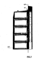
- Figure 3 shows a possible variation extended to a system of 5 layers.
- the horizontal lines LO show how the bottom edges of the front panels are at a height that is the same as or lower than the height of the resistive elements, to intercept the water arriving with an inclination of up to 60° with respect to the vertical.
- the vertical line LV shows the overlapping of the top panel on the cover of the flue on the inside edge 17, to prevent the access of water to the volumes in which the resistors are enclosed.
- the bottom edge of the air inlet panel 10.1 is lower than the height of the resistor.
- the height of the opening between two successive front parts is less than a minimum height considered safe to prevent access to dangerous components: for example it is less than 12 mm, to prevent the entrance of a sphere with diameter 12 mm.
- a minimum height considered safe to prevent access to dangerous components for example it is less than 12 mm, to prevent the entrance of a sphere with diameter 12 mm.
- there may be interposed means suited to prevent access to dangerous components for example by inserting a mesh.
- the cover of the outlet flue 13 in point A prevents access along the line B-C which is intercepted by the end point 17 of the top panel 10.2.
- the main characteristics of the cabinet are: the air flow which passes through each layer of resistors does not pass through the others; the flow is guided, always keeping a substantial component in the vertical direction; the warm flow going out is channelled into a flue.
- a labyrinth is developed such as to prevent the direct access of water respectively according to degree of protection IP23 and IP44.
- None of the panels or lips catches water or prevents the water and/or humidity from flowing downward, away from the resistors.
Landscapes
- Engineering & Computer Science (AREA)
- Power Engineering (AREA)
- Cooling Or The Like Of Electrical Apparatus (AREA)
Claims (7)
- Schrank zur Unterbringung von zwei oder mehr als zwei auf mehreren Etagen (2, 3, 4) angeordneten elektrischen Bauelementen, insbesondere von elektrischen Widerständen, welche Wärme erzeugen, die abgeführt werden muss, wobei dieser Schrank umfasst:trennende Elemente (8, 9, 10), welche zwischen den genannten Etagen angeordnet sind undwelche geeignet sind, Ströme eines kühlenden Mediums dergestalt zu kanalisieren, dass jede Etage (2, 3, 4) von dem durch die konvektive Bewegung getriggerten Luftstrom durchströmt wird, der durch Schlitze (14, 15, 16) direkt von außen kommt, ohne dass dieser von der Luft getroffen wird, die erwärmt wird, wenn sie durch die darunter befindliche Etage tritt;ein hohler Bereich in Form eines Abzugskanals (11, 13) auf der den Schlitzen (14, 15, 16) gegenüber liegenden Seite, wobei die genannten trennenden Elemente (8, 9, 10) die genannten Ströme des Mediums von den genannten Schlitzen (14, 15, 16) zu dem und durch den genannten Abzugskanal (11, 13) befördern,wobei dieser Schrank dadurch gekennzeichnet ist, dass eines (10) der genannten trennenden Elemente (8, 9, 10) an der Oberseite des genannten Schrankes angeordnet ist, um ein Abdeckelement (10) festzulegen und zu bilden.
- Schrank nach Anspruch 1, dadurch gekennzeichnet, dass die genannte Abdeckung (10) ein vorderes Teil (10.1) umfasst, welches dergestalt ausgelegt ist, dass es mit den entsprechenden vorderen Teilen (8.1, 9.1) der genannten anderen trennenden Elemente (8, 9) dergestalt zusammenwirkt, dass das direkte Eindringen von Regen entsprechend einem festgelegten Winkel des maximalen Auftreffens verhindert wird.
- Schrank nach Anspruch 3, dadurch gekennzeichnet dass der genannte Winkel des maximalen Auftreffens 60° in Bezug auf die Vertikale beträgt.
- Schrank nach irgend einem der Ansprüche 1 bis 3, dadurch gekennzeichnet, dass die genannte Abdeckung (10) ein vorderes Teil (10.1) umfasst, welches dergestalt ausgelegt ist, dass es mit den entsprechenden vorderen Teilen (8.1, 9.1) der genannten anderen trennenden Elemente (8, 9) über lippenförmige Mittel (10.4, 8.4) zusammenwirkt, welche an dem genannten vorderen Teil der Abdeckung (10.1) und an den genannten vorderen Teilen (8.1, 9.1) der genannten anderen trennenden Elemente (8, 9) vorhanden sind, so dass an den vorderen Lufteintrittsstellen ein Labyrinth gebildet wird.
- Schrank nach irgend einem der Ansprüche 2 bis 4, dadurch gekennzeichnet, dass die Höhe der Öffnung zwischen den aufeinanderfolgenden vorderen Teilen (10.1, 8.1, 9.1) geringer ist als eine Mindesthöhe wie beispielsweise 12 mm, welche als sicher betrachtet wird, um den Zugang zu gefährlichen Bestandteilen zu verhindern.
- Schrank nach irgend einem der Ansprüche 2 bis 4, dadurch gekennzeichnet, dass in der Öffnung zwischen den genannten aufeinanderfolgenden vorderen Teilen (10.1, 8.1, 91) Mittel eingesetzt wind, welche geeignet sind, den Zugang zu gefährlichen Bestandteilen zu verhindern, wobei die genannten Mittel ein gitter- bzw. siebförmiges Material umfassen.
- Schrank nach irgend einem der vorangehenden Ansprüche, dadurch gekennzeichnet, dass das eine oder die mehreren auf Etagen (2, 3, 4) angeordneten elektrischen Bauelemente, die Wärme erzeugen, welche abzuführen ist, Gruppen von elektrischen Widerständen mit Streifenmodulen umfassen, die aus Metallstreifen (2.1, 2.2, 2.3; 3.1, 3.2, 3.3; 4.1, 4.2, 4.3) bestehen, welche mit Hilfe von isolierenden Abstandsstücken (2.5, 2.6, 2.7, 2.8; 3.5, 3.6, 3.7, 3.8; 4.5, 4.6, 4.7, 4.8) dergestalt voneinander getrennt sind, dass der Durchgang von Kühlmittel durch die Räume der genannten Module ermöglicht wird.
Priority Applications (2)
| Application Number | Priority Date | Filing Date | Title |
|---|---|---|---|
| EP20060425320 EP1855363B1 (de) | 2006-05-11 | 2006-05-11 | Schrank für wärmeerzeugende elektrische Bauelemente |
| ES06425320T ES2401097T3 (es) | 2006-05-11 | 2006-05-11 | Armario para elementos eléctricos que generan calor a disipar |
Applications Claiming Priority (1)
| Application Number | Priority Date | Filing Date | Title |
|---|---|---|---|
| EP20060425320 EP1855363B1 (de) | 2006-05-11 | 2006-05-11 | Schrank für wärmeerzeugende elektrische Bauelemente |
Publications (2)
| Publication Number | Publication Date |
|---|---|
| EP1855363A1 EP1855363A1 (de) | 2007-11-14 |
| EP1855363B1 true EP1855363B1 (de) | 2012-12-12 |
Family
ID=37054419
Family Applications (1)
| Application Number | Title | Priority Date | Filing Date |
|---|---|---|---|
| EP20060425320 Not-in-force EP1855363B1 (de) | 2006-05-11 | 2006-05-11 | Schrank für wärmeerzeugende elektrische Bauelemente |
Country Status (2)
| Country | Link |
|---|---|
| EP (1) | EP1855363B1 (de) |
| ES (1) | ES2401097T3 (de) |
Cited By (2)
| Publication number | Priority date | Publication date | Assignee | Title |
|---|---|---|---|---|
| CN107147025A (zh) * | 2017-06-19 | 2017-09-08 | 福建省三星电气股份有限公司 | 高压开关柜及其制造方法 |
| IT202400001359A1 (it) * | 2024-01-25 | 2025-07-25 | Calzavara S P A | Palo multifunzione modulare per il supporto di dispositivi elettronici. |
Families Citing this family (3)
| Publication number | Priority date | Publication date | Assignee | Title |
|---|---|---|---|---|
| CN110459967B (zh) * | 2019-06-27 | 2021-02-26 | 唐山远宏电力工程有限公司 | 一种电力用高压电力计量箱 |
| CN111799663B (zh) * | 2020-07-10 | 2022-04-12 | 广东电网有限责任公司 | 电力设备防雨罩 |
| CN118841860B (zh) * | 2024-08-30 | 2025-02-28 | 江苏隆兵电气有限公司 | 一种电气控制柜高效散热降噪装置 |
Family Cites Families (4)
| Publication number | Priority date | Publication date | Assignee | Title |
|---|---|---|---|---|
| SU712991A1 (ru) * | 1978-08-10 | 1980-01-30 | Предприятие П/Я В-2785 | Стойка дл радиоэлектронной аппаратуры |
| US5105336A (en) | 1987-07-29 | 1992-04-14 | Lutron Electronics Co., Inc. | Modular multilevel electronic cabinet |
| US5513071A (en) * | 1994-11-28 | 1996-04-30 | Philips Electronics North America Corporation | Electronics housing with improved heat rejection |
| JP2000022373A (ja) | 1998-07-03 | 2000-01-21 | Toshiba Corp | 電子機器 |
-
2006
- 2006-05-11 ES ES06425320T patent/ES2401097T3/es active Active
- 2006-05-11 EP EP20060425320 patent/EP1855363B1/de not_active Not-in-force
Cited By (3)
| Publication number | Priority date | Publication date | Assignee | Title |
|---|---|---|---|---|
| CN107147025A (zh) * | 2017-06-19 | 2017-09-08 | 福建省三星电气股份有限公司 | 高压开关柜及其制造方法 |
| CN107147025B (zh) * | 2017-06-19 | 2019-01-01 | 福建省三星电气股份有限公司 | 高压开关柜及其制造方法 |
| IT202400001359A1 (it) * | 2024-01-25 | 2025-07-25 | Calzavara S P A | Palo multifunzione modulare per il supporto di dispositivi elettronici. |
Also Published As
| Publication number | Publication date |
|---|---|
| ES2401097T3 (es) | 2013-04-16 |
| EP1855363A1 (de) | 2007-11-14 |
Similar Documents
| Publication | Publication Date | Title |
|---|---|---|
| JP6906033B2 (ja) | パッシブ屋根排気システム | |
| US8130494B2 (en) | Equipment rack and associated ventilation system | |
| US6042348A (en) | Protective shutter assembly for a forced air cooling system | |
| US10492337B2 (en) | Cooling rack for server | |
| EP2587175B1 (de) | Lüfterträgerstruktur für Klimaregelmaschinen mit Unterbodenluftstrom | |
| EP1855363B1 (de) | Schrank für wärmeerzeugende elektrische Bauelemente | |
| US20050000199A1 (en) | Baffle filter | |
| US20050167355A1 (en) | Strainer wall for the screening off of a suction space | |
| US7850150B2 (en) | Support grid apparatus and method | |
| US10605467B2 (en) | Outdoor unit for air-conditioning apparatus and method of producing outdoor unit for air-conditioning apparatus | |
| US9883608B2 (en) | Cooling device for cooling a switchgear cabinet | |
| EP2587173B1 (de) | Klimaregelmaschinenstruktur | |
| JP2009008368A (ja) | 電気加熱併用型太陽熱集熱装置 | |
| JP2000320033A (ja) | 建物の断熱システム | |
| EP4040081A1 (de) | Schallisolierungsgehäuse | |
| EP1813877B1 (de) | Innenraumeinheit einer Klimaanlage | |
| RU2596076C2 (ru) | Брызгальные решетки для зон каплепадения или разбрызгивания | |
| CN214664834U (zh) | 一种防水装置和空调器 | |
| JP2512129B2 (ja) | クライオポンプ | |
| WO2013144829A1 (en) | Cell stack heat sink panel with integral heat dissipating fin | |
| US10890352B2 (en) | Air handling unit | |
| US20070193574A1 (en) | Grease filtration system and methods of making and using the same | |
| TWM320293U (en) | Heat-dissipation structure of electric machinery box | |
| EP3169429A1 (de) | Gegenstromfüllmodul und verfahren | |
| FI82136C (fi) | Kassettkombination foer att isolera radiatorer. |
Legal Events
| Date | Code | Title | Description |
|---|---|---|---|
| PUAI | Public reference made under article 153(3) epc to a published international application that has entered the european phase |
Free format text: ORIGINAL CODE: 0009012 |
|
| AK | Designated contracting states |
Kind code of ref document: A1 Designated state(s): AT BE BG CH CY CZ DE DK EE ES FI FR GB GR HU IE IS IT LI LT LU LV MC NL PL PT RO SE SI SK TR |
|
| AX | Request for extension of the european patent |
Extension state: AL BA HR MK YU |
|
| 17P | Request for examination filed |
Effective date: 20080512 |
|
| AKX | Designation fees paid |
Designated state(s): DE ES FR IT |
|
| 17Q | First examination report despatched |
Effective date: 20080630 |
|
| GRAP | Despatch of communication of intention to grant a patent |
Free format text: ORIGINAL CODE: EPIDOSNIGR1 |
|
| RIN1 | Information on inventor provided before grant (corrected) |
Inventor name: VETTORELLO, OSVALDO Inventor name: FINARELLI, DANIELE |
|
| GRAS | Grant fee paid |
Free format text: ORIGINAL CODE: EPIDOSNIGR3 |
|
| GRAA | (expected) grant |
Free format text: ORIGINAL CODE: 0009210 |
|
| RIN1 | Information on inventor provided before grant (corrected) |
Inventor name: FINARELLI, DANIELE GIANLUIGI Inventor name: VETTORELLO, OSVALDO |
|
| AK | Designated contracting states |
Kind code of ref document: B1 Designated state(s): DE ES FR IT |
|
| REG | Reference to a national code |
Ref country code: DE Ref legal event code: R096 Ref document number: 602006033572 Country of ref document: DE Effective date: 20130207 |
|
| REG | Reference to a national code |
Ref country code: ES Ref legal event code: FG2A Ref document number: 2401097 Country of ref document: ES Kind code of ref document: T3 Effective date: 20130416 |
|
| PLBE | No opposition filed within time limit |
Free format text: ORIGINAL CODE: 0009261 |
|
| STAA | Information on the status of an ep patent application or granted ep patent |
Free format text: STATUS: NO OPPOSITION FILED WITHIN TIME LIMIT |
|
| 26N | No opposition filed |
Effective date: 20130913 |
|
| REG | Reference to a national code |
Ref country code: DE Ref legal event code: R097 Ref document number: 602006033572 Country of ref document: DE Effective date: 20130913 |
|
| REG | Reference to a national code |
Ref country code: FR Ref legal event code: PLFP Year of fee payment: 11 |
|
| REG | Reference to a national code |
Ref country code: FR Ref legal event code: PLFP Year of fee payment: 12 |
|
| PGFP | Annual fee paid to national office [announced via postgrant information from national office to epo] |
Ref country code: FR Payment date: 20170530 Year of fee payment: 12 |
|
| PGFP | Annual fee paid to national office [announced via postgrant information from national office to epo] |
Ref country code: IT Payment date: 20170523 Year of fee payment: 12 |
|
| PGFP | Annual fee paid to national office [announced via postgrant information from national office to epo] |
Ref country code: DE Payment date: 20170719 Year of fee payment: 12 Ref country code: ES Payment date: 20170801 Year of fee payment: 12 |
|
| REG | Reference to a national code |
Ref country code: DE Ref legal event code: R119 Ref document number: 602006033572 Country of ref document: DE |
|
| PG25 | Lapsed in a contracting state [announced via postgrant information from national office to epo] |
Ref country code: FR Free format text: LAPSE BECAUSE OF NON-PAYMENT OF DUE FEES Effective date: 20180531 Ref country code: DE Free format text: LAPSE BECAUSE OF NON-PAYMENT OF DUE FEES Effective date: 20181201 Ref country code: IT Free format text: LAPSE BECAUSE OF NON-PAYMENT OF DUE FEES Effective date: 20180511 |
|
| REG | Reference to a national code |
Ref country code: ES Ref legal event code: FD2A Effective date: 20190913 |
|
| PG25 | Lapsed in a contracting state [announced via postgrant information from national office to epo] |
Ref country code: ES Free format text: LAPSE BECAUSE OF NON-PAYMENT OF DUE FEES Effective date: 20180512 |