EP1855932B1 - Sol utilitaire coulissant vers l'exterieur - Google Patents
Sol utilitaire coulissant vers l'exterieur Download PDFInfo
- Publication number
- EP1855932B1 EP1855932B1 EP06737082A EP06737082A EP1855932B1 EP 1855932 B1 EP1855932 B1 EP 1855932B1 EP 06737082 A EP06737082 A EP 06737082A EP 06737082 A EP06737082 A EP 06737082A EP 1855932 B1 EP1855932 B1 EP 1855932B1
- Authority
- EP
- European Patent Office
- Prior art keywords
- floor
- floor panel
- cargo space
- vehicle
- locking
- Prior art date
- Legal status (The legal status is an assumption and is not a legal conclusion. Google has not performed a legal analysis and makes no representation as to the accuracy of the status listed.)
- Expired - Lifetime
Links
Images


Classifications
-
- B—PERFORMING OPERATIONS; TRANSPORTING
- B62—LAND VEHICLES FOR TRAVELLING OTHERWISE THAN ON RAILS
- B62C—VEHICLES DRAWN BY ANIMALS
- B62C1/00—Types of vehicles
- B62C1/04—Load-carrying vehicles
- B62C1/06—Load-carrying vehicles convertible, e.g. with extensible parts, with changeable wheel track
-
- B—PERFORMING OPERATIONS; TRANSPORTING
- B60—VEHICLES IN GENERAL
- B60P—VEHICLES ADAPTED FOR LOAD TRANSPORTATION OR TO TRANSPORT, TO CARRY, OR TO COMPRISE SPECIAL LOADS OR OBJECTS
- B60P1/00—Vehicles predominantly for transporting loads and modified to facilitate loading, consolidating the load, or unloading
- B60P1/003—Vehicles predominantly for transporting loads and modified to facilitate loading, consolidating the load, or unloading vehicles with loading gates
-
- B—PERFORMING OPERATIONS; TRANSPORTING
- B60—VEHICLES IN GENERAL
- B60R—VEHICLES, VEHICLE FITTINGS, OR VEHICLE PARTS, NOT OTHERWISE PROVIDED FOR
- B60R5/00—Compartments within vehicle body primarily intended or sufficiently spacious for trunks, suit-cases, or the like
- B60R5/04—Compartments within vehicle body primarily intended or sufficiently spacious for trunks, suit-cases, or the like arranged at rear of vehicle
Definitions
- the present invention relates generally to a floor assembly for the cargo space of an automotive vehicle, and more particularly to a floor assembly having a slide out floor.
- a floor assembly in accordance with the present invention, includes a floor panel mounted in the cargo space on a floor support for movement along a predetermined path of travel from a first or forward position totally within the cargo space to an extended position. It comprises a locking mechanism which is provided for selectively, releasably locking the floor panel in both the forward position and the extended position. The locking mechanism is further capable of locking the floor panel in a plurality of intermediate positions between the forward position and the extended position.
- anchors may be provided to receive straps for tying down articles on the floor panel.
- the locking mechanism further includes detents spaced apart along the path of travel, and a locking lever engageable with any one of the detents to lock the floor panel in a selected one of its positions.
- a release mechanism is provided to retract the locking lever out of engagement with a detent.
- One object of the invention is to provide a floor assembly for cargo space of an automotive vehicle having the foregoing features and capabilities.
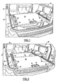
- FIGS. 1 and 2 there is shown an automotive vehicle 20 having a vehicle body 22 provided with a cargo space 24 having a rear opening 26.
- the rear opening 26 is normally closed by a suitable closure having a door or doors, and sometimes including a transom hinged to a lower edge portion of the opening 26.
- the closure forms no part of the invention and is not shown in the drawings.
- the cargo space 24 has a floor assembly 28 which includes a generally horizontal floor panel 30 mounted on a floor support 32. See FIGS. 2-6 .
- the floor support 32 is mounted in fixed position on a rigid body panel 33 of the vehicle body 22. More specifically, the floor support 32 has laterally spaced apart longitudinally extending side rails 34.
- the floor panel 30 has laterally spaced apart side rails 36 which are secured to the underside of the floor panel and which respectively overlie the side rails 34.
- Ball bearings 38 ( FIG. 6 ) support the side rails 36 of the floor panel 30 on the side rails 34 of the floor support for sliding movement of the floor panel lengthwise of the vehicle along a predetermined path of travel from the normal forward position entirely within the cargo space 24 as shown in FIG. 1 to a rearwardly extending position or positions shown in FIG. 2 in which at least the rear portion of the floor panel projects outside of the cargo space 24 and outside of the vehicle.
- FIG. 6 shows the configuration of one of the side rails 34 and one of the side rails 36 and the sliding support for the side rail 36. It will be understood that the configuration of the other of the side rails 34 and the other of the side rails 36 and the sliding support therefor will be the same as in FIG. 6 .
- Locking mechanism 40 ( FIGS. 5-7 ) is provided for locking the floor panel 30 in various positions, including a forward position wholly within the vehicle, a fully rearwardly extended position in which at least a substantial portion of the floor panel 30 is projected outside the cargo space 24 and outside the vehicle, and numerous intermediate positions between the forward position and the fully extended position.
- the locking mechanism 40 comprises locking levers 42 and 44 carried by the floor panel 30, and locking strips 46 and 48 carried by the floor support 32. More specifically, each of the locking levers 42, 44 is pivotally mounted on a pivot pin 50 carried by a bracket 52 attached to one of the side rails 36 of the floor panel 30 (see FIG, 7 ). Each locking lever is generally L-shaped, and has angularly related arms 53 and 54 extending outwardly from the pivot pin 50.
- the locking strips 46 and 48 are rigidly attached to the respective support rails 34 and extend parallel to one another and parallel to the path of travel of the floor panel 30. Each locking strip 46, 48 has a plurality of locking holes or detents 60 equally spaced apart along its length.
- the locking lever 42 overlies the locking strip 46 and the locking lever 44 overlies the locking strip 48.
- Each locking lever has locking dogs 62 on its arm 53 spaced apart the same distance as the detents 60 and adapted to engage in two or more of the detents 60 of the underlying locking strip.
- a tension spring 63 has one end connected to the arm 53 of each locking lever and the opposite end connected to the underlying locking strip. The springs 63 pull the locking levers in a downward direction toward the locking strips for engagement of the dogs in the detents, thereby locking the floor panel in a desired position.
- Release mechanism 68 including cables 70 and 72 is provided to retract the locking levers 42 and 44 to withdraw the dogs 62 from the detents 60 and permit the position of the floor panel to be changed.
- the cable 70 has one end connected to the arm 54 of the locking lever 42, extends around pulleys 74 and 76 on the floor support 32 and has its opposite end attached to an operator 78 pivoted to the floor panel 30.
- the cable 72 has one end connected to the arm 54 of the locking lever 44, extends around pulleys 80 and 82 on the floor support 32 and has its opposite end attached to an operator 84 pivoted to the floor panel 30.
- the operators 78 and 84 may be actuated to pull on the cables 70 and 72 to pivot the locking levers in a direction to withdraw the dogs 62 from the detents 60.
- the operators 78 and 84 are conveniently located at the rear edge of the floor panel. A person may thus easily adjust the position of the floor panel 30 while standing outside the vehicle. Instead of separate operators for each cable, both cables can be attached to a
- Anchors 86 are slidably mounted in longitudinally extending channels 88 secured in laterally spaced apart relation to the upper surface of the floor panel 30.
- Each anchor 86 may be in the form of an eye bolt. Straps, not shown, may be threaded through the eye bolts to tie down articles loaded onto the top surface of the floor panel.
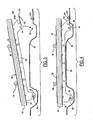
- Each side rail 34 of the floor support 32 has an elongated mounting bracket 90 having a forwardly opening hook 92 at the front end and a downwardly opening slot 94 at the rear end (see FIGS. 3 and 4 ).
- the hooks 92 are transversely aligned and each hook is adapted to engage a retainer 96 secured to the body panel 33.
- the slots 94 are transversely aligned and each slot is adapted to engage a retainer 98 secured to the body panel 33.
- Each mounting bracket 90 has a rearwardly extending projection 100 provided with a hole 102 to receive a bolt 104. To secure the floor assembly in position on the floor panel 33 of the vehicle body, the floor assembly is lowered from the position of FIG. 3 to the position of FIG. 4 , the bolts 104 are extended through the holes 102, and nuts 106 are applied to the bolts.
Landscapes
- Engineering & Computer Science (AREA)
- Mechanical Engineering (AREA)
- Transportation (AREA)
- Body Structure For Vehicles (AREA)
- Lock And Its Accessories (AREA)
Claims (11)
- Ensemble formant sol (28) pour un espace de chargement (24) d'un véhicule automobile (20) comprenant :un support de sol (32) adapté pour être monté sur un panneau de carrosserie (33) du véhicule dans l'espace de chargement, caractérisé en ce que le support de sol comprend des rails s'étendant longitudinalement espacés latéralement (34) avec des supports de montage (90) ayant un crochet s'ouvrant vers l'avant (92) à une extrémité avant et une fente s'ouvrant vers le bas (94) à une extrémité arrière, dans lequel les crochets et les fentes peuvent venir en prise avec des éléments de retenue (96, 98) fixés au panneau de carrosserie,un panneau de sol (30) monté sur le support de sol pour un mouvement le long d'une trajectoire de déplacement prédéterminée d'une première position entièrement à l'intérieur de l'espace de chargement vers une position étendue espacée de la première position ; etun mécanisme de verrouillage (40) pour verrouiller sélectivement de façon libérable le panneau de sol dans la première position, dans la position étendue, et dans une pluralité de positions intermédiaires entre la première position et la position étendue, dans lequel le mécanisme de verrouillage comprend :au moins une bande de verrouillage (46, 48) portée par le support de sol, s'étendant le long de la trajectoire de déplacement, et ayant une pluralité de crans (60) dans une relation espacée le long de la trajectoire de déplacement ;au moins un levier de verrouillage (42, 44) porté par le panneau de sol autour d'un pivot (50) et ayant un premier bras (53) portant au moins une griffe de serrage (62) pour venir en prise avec l'un des crans dans la première position, dans la position étendue, et dans la pluralité de positions intermédiaires entre la première position et la position étendue ; etun mécanisme de libération (68) pour désengager l'au moins un levier de verrouillage desdits crans, ledit mécanisme de libération comprenant au moins un câble (70, 72) et au moins un actionneur (78, 84), l'au moins un câble étant couplé à l'au moins un levier de verrouillage, l'au moins un actionneur étant positionné au niveau d'un bord arrière du panneau de sol, l'actionneur pouvant être actionné pour ajuster la position du panneau de sol le long de la trajectoire de déplacement en actionnant le câble pour faire pivoter l'au moins un levier de verrouillage dans une direction pour retirer l'au moins une griffe de serrage des crans.
- Ensemble formant sol (28) selon la revendication 1, dans lequel ledit panneau de sol (30) dans ladite position étendue s'étend à l'extérieur de l'espace de chargement (24).
- Ensemble formant sol (28) selon la revendication 2, comprenant en outre une ouverture (26) vers l'espace de chargement (24) dans une partie arrière du véhicule (20), ladite trajectoire de déplacement s'étendant vers l'arrière du véhicule, ledit panneau de sol (30) dans ladite position étendue s'étendant à travers l'ouverture avec au moins une partie arrière du panneau de sol s'étendant vers l'arrière à l'extérieur du véhicule.
- Ensemble formant sol (28) selon la revendication 1, dans lequel ledit mécanisme de verrouillage (40) est configuré pour maintenir la mise en prise de la griffe de serrage (62) dans le cran (60) afin de fixer le panneau de sol à la première position, à la position étendue, et à chacune de la pluralité de positions intermédiaires.
- Ensemble formant sol (28) selon la revendication 1, comprenant en outre un ressort (63) pour solliciter ledit levier de verrouillage (42, 44) dans une direction vers la bande de verrouillage (46, 48) pour maintenir la mise en prise de la griffe de serrage (62) avec les crans (60).
- Ensemble formant sol (28) selon la revendication 1, dans lequel le levier de verrouillage (42,44) est en forme de L, ayant des bras en relation angulaire (53, 54) s'étendant vers l'extérieur à partir du pivot (50) de celui-ci, la griffe de serrage (62) étant montée sur l'un des bras, l'autre bras étant fixé au câble (70, 72).
- Ensemble formant sol (28) selon la revendication 6, dans lequel ledit panneau de sol (30) dans ladite position étendue s'étend à l'extérieur de l'espace de chargement (24).
- Ensemble formant sol (28) selon la revendication 7, comprenant en outre une ouverture (26) vers l'espace de chargement (24) dans une partie arrière du véhicule, la trajectoire de déplacement s'étendant vers l'arrière du véhicule (20), le panneau de sol (30) dans la position étendue s'étendant à travers l'ouverture avec au moins une partie arrière du panneau de sol s'étendant vers l'arrière à l'extérieur du véhicule.
- Ensemble formant sol (28) selon la revendication 8, comprenant en outre des ancrages (86) pour attacher des articles sur le panneau de sol (30) et des canaux (88) sur le panneau de sol pour supporter de manière coulissante les ancrages dans des positions ajustées.
- Ensemble formant sol (28) selon la revendication 1, comprenant en outre des ancrages (86) portés sur le panneau de sol (30) pour attacher des articles sur le panneau de sol.
- Ensemble formant sol (28) selon la revendication 1, dans lequel ledit ensemble formant sol est monté de façon amovible dans l'espace de chargement (24) par des éléments de retenue (96, 98) venant en prise avec des crochets (90) sur le support de sol (32).
Applications Claiming Priority (2)
| Application Number | Priority Date | Filing Date | Title |
|---|---|---|---|
| US11/073,441 US7393036B2 (en) | 2005-03-07 | 2005-03-07 | Slide out cargo floor |
| PCT/US2006/007861 WO2006096611A2 (fr) | 2005-03-07 | 2006-03-06 | Sol utilitaire coulissant vers l'exterieur |
Publications (3)
| Publication Number | Publication Date |
|---|---|
| EP1855932A2 EP1855932A2 (fr) | 2007-11-21 |
| EP1855932A4 EP1855932A4 (fr) | 2011-07-27 |
| EP1855932B1 true EP1855932B1 (fr) | 2012-11-14 |
Family
ID=36943445
Family Applications (1)
| Application Number | Title | Priority Date | Filing Date |
|---|---|---|---|
| EP06737082A Expired - Lifetime EP1855932B1 (fr) | 2005-03-07 | 2006-03-06 | Sol utilitaire coulissant vers l'exterieur |
Country Status (6)
| Country | Link |
|---|---|
| US (1) | US7393036B2 (fr) |
| EP (1) | EP1855932B1 (fr) |
| KR (1) | KR101324371B1 (fr) |
| CN (1) | CN101500846B (fr) |
| CA (1) | CA2600671C (fr) |
| WO (1) | WO2006096611A2 (fr) |
Families Citing this family (33)
| Publication number | Priority date | Publication date | Assignee | Title |
|---|---|---|---|---|
| DE102006043223B4 (de) * | 2006-09-11 | 2011-03-17 | Kipp Gmbh & Co. Kg Cargo & Safety Systems | Bodenplatte für einen Laderaum |
| GB0704736D0 (en) * | 2007-03-12 | 2007-04-18 | Accuride Int Ltd | A movable load surface |
| DE102007044910A1 (de) * | 2007-09-19 | 2009-04-09 | Brose Fahrzeugteile Gmbh & Co. Kommanditgesellschaft, Coburg | Ladeboden für Kraftfahrzeuge |
| KR100911559B1 (ko) * | 2007-11-13 | 2009-08-10 | 기아자동차주식회사 | 통합패키지 수직 장착용 프레임 구조 |
| USD603776S1 (en) * | 2007-12-21 | 2009-11-10 | Honda Motor Co., Ltd. | Portion of a vehicle interior lining |
| EP2105352B1 (fr) * | 2008-03-26 | 2013-11-06 | Fiat Group Automobiles S.p.A. | Plancher porte-charge mobile pour le coffre d'un véhicule à moteur |
| US8215692B2 (en) * | 2009-07-21 | 2012-07-10 | Navistar Canada, Inc. | Adjustable length delivery vehicle |
| US9511690B2 (en) | 2012-04-23 | 2016-12-06 | Global Ip Holdings, Llc | Cargo management system including a vehicle load floor having a cellulose-based core and made by a composite, compression molding process and having a wood grain finish |
| US9527268B2 (en) | 2012-04-23 | 2016-12-27 | Global Ip Holdings, Llc | Method of making a sandwich-type composite panel having a cellulose-based core and a living hinge and panel obtained by performing the method |
| US9539958B2 (en) | 2012-04-23 | 2017-01-10 | Global Ip Holdings, Llc | Assembly including a compression-molded, composite panel having a cellulose-based core and a hinged mounting flange |
| US9567037B2 (en) | 2012-05-24 | 2017-02-14 | Global Ip Holdings, Llc | Deep-drawn marine hull having a sandwich structure with a cellulose-based core and watercraft utilizing same |
| US11518136B2 (en) | 2012-05-24 | 2022-12-06 | Global Ip Holdings, Llc | Marine decking with sandwich-type construction and method of making same |
| US11214035B2 (en) | 2012-05-24 | 2022-01-04 | Global Ip Holdings, Llc | Marine decking with sandwich-type construction and method of making same |
| US20170267315A1 (en) | 2012-05-24 | 2017-09-21 | Global Ip Holdings, Llc | Marine decking with sandwich-type construction and method of making same |
| US9873488B2 (en) | 2012-05-24 | 2018-01-23 | Global Ip Holdings Llc | Deep-drawn marine hull having a sandwich structure and watercraft utilizing same |
| DE102012023470A1 (de) | 2012-11-30 | 2014-06-05 | Volkswagen Aktiengesellschaft | Anordnung zur Lagerung eines Ladebodens und Fahrzeug mit einer derartigen Anordnung |
| US10166704B2 (en) | 2013-02-08 | 2019-01-01 | Global Ip Holdings, Llc | Method of making a laminated trim component at a pair of spaced first and second molding stations |
| US10532499B2 (en) | 2013-02-08 | 2020-01-14 | Global Ip Holdings, Llc | Method of making a laminated trim component |
| US9707725B2 (en) | 2013-02-08 | 2017-07-18 | Global Ip Holdings, Llc | Method of making a sandwich-type, compression-molded, composite component having a cellulose-based core and improved surface appearance |
| US10279512B2 (en) | 2013-02-08 | 2019-05-07 | Global Ip Holdings, Llc | Method of making a laminated trim component at a molding station |
| US10618203B2 (en) | 2013-02-08 | 2020-04-14 | Global Ip Holdings, Llc | Method of making a trimmed, laminated trim component |
| US9770849B2 (en) | 2013-02-08 | 2017-09-26 | Global Ip Holdings, Llc | Method of making a sandwich-type, compression-molded, composite component having improved surface appearance |
| US10250183B2 (en) * | 2013-10-25 | 2019-04-02 | Joseph O. Edmunds | Modular solar power generator |
| CN103661062A (zh) * | 2013-11-28 | 2014-03-26 | 安得物流股份有限公司 | 便捷装卸车厢 |
| US10472003B2 (en) | 2016-11-17 | 2019-11-12 | Hyundai America Technical Center, Inc. | Integrated extended bed assembly for vehicle |
| CN106627301A (zh) * | 2017-01-12 | 2017-05-10 | 临沂大学 | 一种物流车以及物流方法 |
| US11148598B1 (en) * | 2017-02-14 | 2021-10-19 | Francis Eman-Henshaw | Truck bed extension system and method of use |
| CZ309168B6 (cs) * | 2020-07-07 | 2022-04-06 | ŠKODA AUTO a.s. | Stolek na nákladovou hranu vozidla |
| US12246653B2 (en) | 2021-12-13 | 2025-03-11 | Adrian Steel Company | Slide out device for vehicle |
| KR20240038386A (ko) | 2022-09-16 | 2024-03-25 | 현대자동차주식회사 | 러기지 공간 확장을 위한 슬라이딩 및 회전 보드구조 |
| US20240227682A9 (en) * | 2022-10-24 | 2024-07-11 | Lear Corporation | Cargo-module arrangement for a vehicle |
| US12496976B2 (en) * | 2023-04-11 | 2025-12-16 | Ford Global Technologies, Llc | Cargo floor |
| DE102024003416A1 (de) * | 2024-10-17 | 2025-05-28 | Mercedes-Benz Group AG | Laderaumbodensystem für einen Laderaum eines Kraftwagens sowie Verfahren |
Family Cites Families (9)
| Publication number | Priority date | Publication date | Assignee | Title |
|---|---|---|---|---|
| JPH08158767A (ja) * | 1994-12-05 | 1996-06-18 | Pika Corp:Kk | 伸縮部材のロック装置 |
| US5513941A (en) * | 1995-02-21 | 1996-05-07 | Kulas; Kenneth K. | Rolling cargo apparatus |
| US6120075A (en) * | 1997-12-30 | 2000-09-19 | Terry; Kenneth A. | Portable extendable cargo deck |
| ATE270631T1 (de) * | 1998-03-12 | 2004-07-15 | Fulterer Gmbh | Ausziehvorrichtung |
| DE10012767B4 (de) * | 2000-03-16 | 2007-05-24 | Webasto Ag | Ladesystem für den Laderaum eines Fahrzeugs |
| US6464274B2 (en) * | 2001-02-15 | 2002-10-15 | Mink & Associates, Llc | Slidable assembly with interlocking guide and rotatable members useful for movable motor vehicle floors and extensions |
| US6503036B1 (en) * | 2002-02-08 | 2003-01-07 | Lawrence M. Bequette | Vehicle sliding floor extension and cargo brace |
| DE10333354A1 (de) * | 2003-07-23 | 2005-03-03 | Alpha Engineering Services Gmbh | Ausziebarer Ladeboden für Kfz. |
| US7121603B2 (en) * | 2004-12-10 | 2006-10-17 | General Motors Corporation | Sliding load floor |
-
2005
- 2005-03-07 US US11/073,441 patent/US7393036B2/en not_active Expired - Lifetime
-
2006
- 2006-03-06 KR KR1020077022835A patent/KR101324371B1/ko not_active Expired - Lifetime
- 2006-03-06 CN CN2006800073631A patent/CN101500846B/zh not_active Expired - Fee Related
- 2006-03-06 CA CA2600671A patent/CA2600671C/fr not_active Expired - Fee Related
- 2006-03-06 EP EP06737082A patent/EP1855932B1/fr not_active Expired - Lifetime
- 2006-03-06 WO PCT/US2006/007861 patent/WO2006096611A2/fr not_active Ceased
Also Published As
| Publication number | Publication date |
|---|---|
| US7393036B2 (en) | 2008-07-01 |
| US20060197351A1 (en) | 2006-09-07 |
| CN101500846A (zh) | 2009-08-05 |
| EP1855932A4 (fr) | 2011-07-27 |
| CN101500846B (zh) | 2013-07-31 |
| WO2006096611A3 (fr) | 2008-10-23 |
| WO2006096611A2 (fr) | 2006-09-14 |
| KR20080018859A (ko) | 2008-02-28 |
| CA2600671A1 (fr) | 2006-09-14 |
| EP1855932A2 (fr) | 2007-11-21 |
| KR101324371B1 (ko) | 2013-11-01 |
| CA2600671C (fr) | 2013-08-06 |
Similar Documents
| Publication | Publication Date | Title |
|---|---|---|
| CA2600671C (fr) | Sol utilitaire coulissant vers l'exterieur | |
| US20220242212A1 (en) | Tonneau cover access panel | |
| US6308874B1 (en) | Roof rack assembly | |
| US5971465A (en) | Tailgate ramp system | |
| CN106608216B (zh) | 包含标准接口板连接的棘轮栓系装置 | |
| US20050079036A1 (en) | Ladder rack system | |
| US20090243331A1 (en) | Tonneau cover cargo containment track rail system | |
| US8328266B2 (en) | Pick-up style utility vehicle with expandable cargo bed | |
| US20170120736A1 (en) | Tonneau cover access panel | |
| WO2012044880A2 (fr) | Système de rangement pour véhicule | |
| EP3081417A1 (fr) | Bâche ayant un système de tension avec câbles | |
| US9156410B2 (en) | Roof-rack mechanism for automobile | |
| US7201418B2 (en) | Sliding vehicle load floor | |
| US20120298678A1 (en) | Vehicle modular storage system | |
| US20040017091A1 (en) | Dismountable seat for an automobile capable of being automatically tumbled and mounted in a face-to-face manner | |
| JP2003341431A (ja) | 自動車のラゲージフロア装置 | |
| US20070122260A1 (en) | Vehicle lift | |
| KR20090129375A (ko) | 차량 물품 캐리어 | |
| US9592756B1 (en) | Seat assemblies for vehicles | |
| US8240963B2 (en) | Cargo hold-down device for a load-carrying bed of a vehicle | |
| US7121778B2 (en) | Device to secure cargo | |
| JP4255590B2 (ja) | 後煽り装置 | |
| US20260109301A1 (en) | Vehicle bicycle carrier assembly | |
| CA2211349C (fr) | Systeme de rampe sur hayon | |
| JP3616384B2 (ja) | 跳上げシートのロック装置 |
Legal Events
| Date | Code | Title | Description |
|---|---|---|---|
| PUAI | Public reference made under article 153(3) epc to a published international application that has entered the european phase |
Free format text: ORIGINAL CODE: 0009012 |
|
| 17P | Request for examination filed |
Effective date: 20071002 |
|
| AK | Designated contracting states |
Kind code of ref document: A2 Designated state(s): AT BE BG CH CY CZ DE DK EE ES FI FR GB GR HU IE IS IT LI LT LU LV MC NL PL PT RO SE SI SK TR |
|
| AX | Request for extension of the european patent |
Extension state: AL BA HR MK YU |
|
| DAX | Request for extension of the european patent (deleted) | ||
| R17D | Deferred search report published (corrected) |
Effective date: 20081023 |
|
| RIC1 | Information provided on ipc code assigned before grant |
Ipc: B60P 1/00 20060101AFI20081118BHEP |
|
| RBV | Designated contracting states (corrected) |
Designated state(s): DE FR GB IT |
|
| RAP1 | Party data changed (applicant data changed or rights of an application transferred) |
Owner name: CHRYSLER GROUP LLC |
|
| A4 | Supplementary search report drawn up and despatched |
Effective date: 20110629 |
|
| REG | Reference to a national code |
Ref country code: DE Ref legal event code: R079 Ref document number: 602006033049 Country of ref document: DE Free format text: PREVIOUS MAIN CLASS: B60P0001000000 Ipc: B60R0005040000 |
|
| GRAP | Despatch of communication of intention to grant a patent |
Free format text: ORIGINAL CODE: EPIDOSNIGR1 |
|
| RIC1 | Information provided on ipc code assigned before grant |
Ipc: B60R 5/04 20060101AFI20120525BHEP |
|
| GRAS | Grant fee paid |
Free format text: ORIGINAL CODE: EPIDOSNIGR3 |
|
| GRAA | (expected) grant |
Free format text: ORIGINAL CODE: 0009210 |
|
| AK | Designated contracting states |
Kind code of ref document: B1 Designated state(s): DE FR GB IT |
|
| REG | Reference to a national code |
Ref country code: GB Ref legal event code: FG4D |
|
| REG | Reference to a national code |
Ref country code: DE Ref legal event code: R096 Ref document number: 602006033049 Country of ref document: DE Effective date: 20130110 |
|
| PLBE | No opposition filed within time limit |
Free format text: ORIGINAL CODE: 0009261 |
|
| STAA | Information on the status of an ep patent application or granted ep patent |
Free format text: STATUS: NO OPPOSITION FILED WITHIN TIME LIMIT |
|
| 26N | No opposition filed |
Effective date: 20130815 |
|
| REG | Reference to a national code |
Ref country code: DE Ref legal event code: R097 Ref document number: 602006033049 Country of ref document: DE Effective date: 20130815 |
|
| REG | Reference to a national code |
Ref country code: FR Ref legal event code: PLFP Year of fee payment: 11 |
|
| REG | Reference to a national code |
Ref country code: FR Ref legal event code: PLFP Year of fee payment: 12 |
|
| REG | Reference to a national code |
Ref country code: FR Ref legal event code: PLFP Year of fee payment: 13 |
|
| PGFP | Annual fee paid to national office [announced via postgrant information from national office to epo] |
Ref country code: FR Payment date: 20210325 Year of fee payment: 16 Ref country code: IT Payment date: 20210323 Year of fee payment: 16 |
|
| PGFP | Annual fee paid to national office [announced via postgrant information from national office to epo] |
Ref country code: DE Payment date: 20210329 Year of fee payment: 16 Ref country code: GB Payment date: 20210329 Year of fee payment: 16 |
|
| REG | Reference to a national code |
Ref country code: DE Ref legal event code: R119 Ref document number: 602006033049 Country of ref document: DE |
|
| GBPC | Gb: european patent ceased through non-payment of renewal fee |
Effective date: 20220306 |
|
| PG25 | Lapsed in a contracting state [announced via postgrant information from national office to epo] |
Ref country code: GB Free format text: LAPSE BECAUSE OF NON-PAYMENT OF DUE FEES Effective date: 20220306 Ref country code: FR Free format text: LAPSE BECAUSE OF NON-PAYMENT OF DUE FEES Effective date: 20220331 Ref country code: DE Free format text: LAPSE BECAUSE OF NON-PAYMENT OF DUE FEES Effective date: 20221001 |
|
| PG25 | Lapsed in a contracting state [announced via postgrant information from national office to epo] |
Ref country code: IT Free format text: LAPSE BECAUSE OF NON-PAYMENT OF DUE FEES Effective date: 20220306 |