EP1855936B1 - Cabine pour camion-tracteur - Google Patents
Cabine pour camion-tracteur Download PDFInfo
- Publication number
- EP1855936B1 EP1855936B1 EP05711118A EP05711118A EP1855936B1 EP 1855936 B1 EP1855936 B1 EP 1855936B1 EP 05711118 A EP05711118 A EP 05711118A EP 05711118 A EP05711118 A EP 05711118A EP 1855936 B1 EP1855936 B1 EP 1855936B1
- Authority
- EP
- European Patent Office
- Prior art keywords
- cab
- step arrangement
- side panel
- wall
- backward
- Prior art date
- Legal status (The legal status is an assumption and is not a legal conclusion. Google has not performed a legal analysis and makes no representation as to the accuracy of the status listed.)
- Expired - Lifetime
Links
- 239000000446 fuel Substances 0.000 description 2
- 239000002828 fuel tank Substances 0.000 description 2
- 101100494448 Caenorhabditis elegans cab-1 gene Proteins 0.000 description 1
- 229910000831 Steel Inorganic materials 0.000 description 1
- 230000015572 biosynthetic process Effects 0.000 description 1
- 230000000295 complement effect Effects 0.000 description 1
- 238000004519 manufacturing process Methods 0.000 description 1
- 239000010959 steel Substances 0.000 description 1
- 238000003466 welding Methods 0.000 description 1
Images
Classifications
-
- B—PERFORMING OPERATIONS; TRANSPORTING
- B62—LAND VEHICLES FOR TRAVELLING OTHERWISE THAN ON RAILS
- B62D—MOTOR VEHICLES; TRAILERS
- B62D33/00—Superstructures for load-carrying vehicles
- B62D33/06—Drivers' cabs
-
- B—PERFORMING OPERATIONS; TRANSPORTING
- B60—VEHICLES IN GENERAL
- B60R—VEHICLES, VEHICLE FITTINGS, OR VEHICLE PARTS, NOT OTHERWISE PROVIDED FOR
- B60R3/00—Arrangements of steps or ladders facilitating access to or on the vehicle, e.g. running-boards
- B60R3/02—Retractable steps or ladders, e.g. movable under shock
-
- B—PERFORMING OPERATIONS; TRANSPORTING
- B62—LAND VEHICLES FOR TRAVELLING OTHERWISE THAN ON RAILS
- B62D—MOTOR VEHICLES; TRAILERS
- B62D35/00—Vehicle bodies characterised by streamlining
- B62D35/001—For commercial vehicles or tractor-trailer combinations, e.g. caravans
Definitions
- the present invention relates to a cab for a motor-driven tractor vehicle, comprising a body that has a rear body wall and side walls that are provided with side panels that form an extension of at least a part of each side wall in a backward direction to a plane at a distance from the rear body wall and that are arranged to bridge an air space between the rear body wall and a front wall on a connected trailer in order to deflect the wind from the said space between the rear body wall of the cab and the front wall of the trailer while the vehicle is being driven, with the front edge of at least one side panel being joined to the rear edge of the associated side wall in such a way that it can pivot, in order to enable the side panel to be swung between a backward-directed position and a sideways-directed position.
- tractor vehicles for semi-trailers have cab bodies with side panels, so-called side spoilers, of the type described above, that are intended to prevent the formation of eddies in the air space between the rear wall of the cab and front wall of the semi-trailer, as such eddies increase the air resistance of the complete unit.
- cables and pipes from the tractor vehicle's electrical and compressed-air systems must be connected to the electrical and compressed-air systems of the semi-trailer.
- the driver connects these cables and pipes manually to connections on the semi-trailer using quick-release connections. In order to be able to do this, the driver must climb up in the space behind the cab and, for this purpose, some form of step arrangement integrated into the tractor vehicle immediately behind the cab is required.
- a common solution is to integrate steps into the tractor vehicle's fuel tank that is usually located immediately behind the cab on the side of the chassis, with the outside of the tank in line with the side wall of the vehicle cab. As these steps cannot project out to the side beyond the side of the tank, the steps are designed in such a way that they project into the interior of the tank, which, however, results in them encroaching on the space for fuel.
- the steps are formed of deep-pressed bowls made of steel plate that are welded into holes cut in the side of the tank, which contributes to increasing the cost of the tank.
- the object of the present invention is to achieve an integrated step arrangement for a vehicle cab of the type described in the introduction, that does not encroach on the fuel space in the tank and that, in addition, makes it possible to reduce the cost of manufacturing the tank.
- the said side panel that can pivot on the side wall, and that, in the backward-directed position, faces inwards towards the said space with a step arrangement that can be moved between an upper storage position, in which it is at least essentially concealed behind the side panel, and an in-use position, in which it has a part with steps located below the lower edge of the side panel.
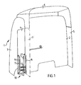
- 1 represents in general the body of a cab of a tractor vehicle for semi-trailers
- 2 represents the rear wall of the body
- 3 represents one of its side walls
- 4 and 5 represent two side air deflectors, so-called side spoilers
- 6 represents a roof spoiler.
- the side spoiler 4 is attached to the side wall 3 of the body by means of a hinge arrangement (not shown), in such a way that it can pivot, in order to be able to be swung between a backward-directed position shown by chain-dotted lines and a swung-out position shown by solid lines that is at right angles to the backward-directed position.
- a hinge arrangement not shown
- the side spoiler can be locked in the respective positions.
- a step arrangement is mounted on the inside of the side spoiler 4.
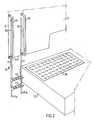
- the step arrangement 10 consists of two side uprights 11 arranged a short distance apart, two steps 12 that are attached by their ends, for example by welding, between the uprights 11, and two tracks 13 that are attached to the inside of the side spoiler 4.
- the uprights 11 are mounted in the tracks 13 in such a way that they can move telescopically.
- the uprights 11 can have a T-profile and the tracks 13 can have a corresponding complementary T-slot.
- Handrails 14 are mounted on each side of the tracks 13.
- step 12 is attached between the side uprights 11 in a step arrangement, which step arrangement can otherwise be described in the same way as the step arrangement described above, which step arrangement is arranged on the inside of the side spoiler 4.
- the side spoiler 4 is shown in a swung-out position in order to make room for the driver to climb up on a platform 16 ( Figure 2 ) that is mounted on the vehicle's fuel tank 15 in the space behind the cab 1.
- the step arrangement 10 is shown here in its storage position and, in the embodiment shown, has its lower end located above the lower edge 4a of the side spoiler 4.
- the step arrangement 10 is shown with the side uprights 11 lowered, so that the step 12 lies on a level that makes it easy for the driver to climb up on the platform 16.
- the side uprights 11 are preferably dimensioned in such a way that their lower ends 11a rest against the subframe of the vehicle, when the step 12 lies at the level shown in Figure 2 in relation to the platform 16. In this way, the hinge arrangement of the side spoiler 4 is non-loadbearing when the step 12 is loadbearing.
- step arrangement 10 that can be moved telescopically in relation to the side spoiler 4.
- step arrangement it is of course possible, as an alternative to the described embodiment, to arrange the step arrangement to be suspended on the side spoiler in such a way that it can pivot, to enable it to be swung between an upper storage position and a lower in-use position.
- the advantage of the telescopic embodiment described above is, however, that the side uprights 11 can always be lowered as much as necessary in order for their lower ends 11a to be supported on the subframe of the vehicle, irrespective of whether this is uneven.
Landscapes
- Engineering & Computer Science (AREA)
- Mechanical Engineering (AREA)
- Chemical & Material Sciences (AREA)
- Combustion & Propulsion (AREA)
- Transportation (AREA)
- Vehicle Step Arrangements And Article Storage (AREA)
- Body Structure For Vehicles (AREA)
- Arrangement Or Mounting Of Propulsion Units For Vehicles (AREA)
- Automatic Cycles, And Cycles In General (AREA)
Claims (5)
- Cabine destinée à un véhicule tracteur entraîné par moteur, comprenant une carrosserie qui a une paroi de carrosserie arrière (2) et des parois latérales (3) qui sont munies de panneaux latéraux (4, 5) qui forment un prolongement d'au moins une partie de chaque paroi latérale dans une direction vers l'arrière par rapport à un plan situé à une distance de la paroi de carrosserie arrière, et qui sont agencés pour chevaucher un espace d'air situé entre la paroi de carrosserie arrière et une paroi avant d'une remorque raccordée pour dévier le vent depuis ledit espace situé entre la paroi de carrosserie arrière de la cabine et la paroi avant de la remorque tandis que le véhicule est entraîné, au moins le bord avant d'un premier panneau latéral (4) étant fixé sur le bord arrière de la paroi latérale associée de telle manière qu'il peut pivoter, pour lui permettre d'être basculé entre une position dirigée vers l'arrière et une position dirigée vers le côté, caractérisée en ce que, dans la position dirigée vers l'arrière, ledit panneau latéral pivotant (4) a un agencement de marches (10) situé sur le côté qui est dirigé vers l'intérieur en direction dudit espace, lequel agencement de marches peut se déplacer entre une position de rangement supérieure, dans laquelle il est au moins essentiellement caché derrière le panneau latéral, et une position d'utilisation, dans laquelle il a une partie munie de marches (12) positionnées sous le bord inférieur (4a) du panneau latéral.
- Cabine selon la revendication 1, caractérisée en ce que lorsque l'agencement de marches (10) est dans sa position d'utilisation, ladite partie a au moins deux marches (12) situées sous le bord inférieur (4a) du panneau latéral.
- Cabine selon la revendication 1 ou 2, caractérisée en ce que l'agencement de marches (10) a des pattes de support (11) qui appuient contre le sous-châssis du véhicule lorsque l'agencement de marches est dans sa position d'utilisation.
- Cabine selon l'une quelconque des revendications 1 à 3, caractérisée en ce que les marches (12) de l'agencement de marches sont fixées sur des éléments droits verticaux (11) qui sont agencés à une courte distance, lesquels montants sont montés d'une manière telle qu'ils peuvent se déplacer dans des pistes verticales (13) qui sont fixées sur le panneau latéral (4).
- Cabine selon l'une quelconque des revendications 1 à 4, caractérisée en ce que l'agencement de marches (10) est supporté entre deux mains courantes (14) qui sont fixées sur le panneau latéral (4).
Applications Claiming Priority (1)
| Application Number | Priority Date | Filing Date | Title |
|---|---|---|---|
| PCT/SE2005/000258 WO2006091129A1 (fr) | 2005-02-22 | 2005-02-22 | Cabine pour camion-tracteur |
Publications (2)
| Publication Number | Publication Date |
|---|---|
| EP1855936A1 EP1855936A1 (fr) | 2007-11-21 |
| EP1855936B1 true EP1855936B1 (fr) | 2008-12-31 |
Family
ID=36927674
Family Applications (1)
| Application Number | Title | Priority Date | Filing Date |
|---|---|---|---|
| EP05711118A Expired - Lifetime EP1855936B1 (fr) | 2005-02-22 | 2005-02-22 | Cabine pour camion-tracteur |
Country Status (7)
| Country | Link |
|---|---|
| US (1) | US7637557B2 (fr) |
| EP (1) | EP1855936B1 (fr) |
| CN (1) | CN100554065C (fr) |
| AT (1) | ATE419167T1 (fr) |
| BR (1) | BRPI0520101A2 (fr) |
| DE (1) | DE602005012157D1 (fr) |
| WO (1) | WO2006091129A1 (fr) |
Families Citing this family (13)
| Publication number | Priority date | Publication date | Assignee | Title |
|---|---|---|---|---|
| CN101654122B (zh) * | 2008-08-21 | 2012-01-04 | 河南农业大学 | 大客车门梯 |
| GB2498809B (en) | 2012-01-30 | 2015-05-06 | Wr Ind Ltd | Drag reduction device and a vehicle comprising the device |
| DE102014003155A1 (de) * | 2014-03-03 | 2015-09-03 | Liebherr-Mining Equipment Colmar Sas | Arbeitsmaschine, insbesondere Muldenkipper oder Truck |
| US9404238B1 (en) * | 2015-01-10 | 2016-08-02 | Bauer Maschinen Gmbh | Construction machine |
| US10981609B2 (en) | 2015-12-30 | 2021-04-20 | Nikola Corporation | Systems, methods, and devices for an automobile door or window |
| US11001129B2 (en) | 2015-12-30 | 2021-05-11 | Nikola Corporation | Cargo door for semi-truck |
| US10661844B2 (en) * | 2015-12-30 | 2020-05-26 | Nikola Corporation | Systems, methods, and devices for an automobile door or window |
| US10077084B2 (en) | 2015-12-30 | 2018-09-18 | Nikola Corporation | Systems, methods, and devices for an automobile door or window |
| DE102019005278A1 (de) * | 2019-07-26 | 2021-01-28 | Man Truck & Bus Se | Kraftfahrzeug mit Tank |
| DE102019008489A1 (de) * | 2019-12-06 | 2021-06-10 | Man Truck & Bus Se | Kraftfahrzeug mit Dachspoiler |
| US12595119B2 (en) | 2021-06-29 | 2026-04-07 | Oshkosh Corporation | Vehicle with thermal management system |
| US12559182B2 (en) * | 2022-03-31 | 2026-02-24 | Oshkosh Corporation | Transition door for refuse vehicle |
| CN116118879B (zh) * | 2023-02-21 | 2026-03-03 | 一汽解放汽车有限公司 | 驾驶室装置和挂车 |
Family Cites Families (10)
| Publication number | Priority date | Publication date | Assignee | Title |
|---|---|---|---|---|
| US4925235A (en) * | 1989-08-25 | 1990-05-15 | Paccar Inc | Cab fairing mounting for truck |
| US4991906A (en) * | 1989-08-25 | 1991-02-12 | Paccar Inc. | Cab skirt fairing mounting for below a truck sleeper box |
| US5054799A (en) * | 1989-08-25 | 1991-10-08 | Paccar Inc. | Cab fairing mounting for truck |
| US5788321A (en) * | 1996-05-22 | 1998-08-04 | Freightliner Corporation | Removable side fairing for a vehicle |
| CN1205283A (zh) * | 1997-06-20 | 1999-01-20 | 日野自动车工业株式会社 | 车用梯子的安装结构 |
| CA2261907A1 (fr) * | 1999-02-05 | 2000-08-05 | Joseph Brady | Boite de rangement pour camions |
| CN1285293A (zh) * | 1999-08-22 | 2001-02-28 | 罗进南 | 装有低风阻双通道载人小室的平头式载货汽车 |
| DE10000006C2 (de) * | 2000-01-03 | 2003-09-18 | Herbert Michels | Einstiegsverkleidung für ein Fahrerhaus eines Lastkraftwagens |
| CN2621998Y (zh) * | 2003-06-03 | 2004-06-30 | 张凌元 | 车用折叠式踏板梯 |
| CN2637291Y (zh) * | 2003-07-10 | 2004-09-01 | 何太银 | 内藏式自装卸半挂运输车 |
-
2005
- 2005-02-22 DE DE602005012157T patent/DE602005012157D1/de not_active Expired - Lifetime
- 2005-02-22 US US11/721,181 patent/US7637557B2/en not_active Expired - Fee Related
- 2005-02-22 CN CNB2005800471437A patent/CN100554065C/zh not_active Expired - Fee Related
- 2005-02-22 BR BRPI0520101-2A patent/BRPI0520101A2/pt not_active IP Right Cessation
- 2005-02-22 WO PCT/SE2005/000258 patent/WO2006091129A1/fr not_active Ceased
- 2005-02-22 AT AT05711118T patent/ATE419167T1/de not_active IP Right Cessation
- 2005-02-22 EP EP05711118A patent/EP1855936B1/fr not_active Expired - Lifetime
Also Published As
| Publication number | Publication date |
|---|---|
| ATE419167T1 (de) | 2009-01-15 |
| EP1855936A1 (fr) | 2007-11-21 |
| CN101107158A (zh) | 2008-01-16 |
| US7637557B2 (en) | 2009-12-29 |
| US20090250970A1 (en) | 2009-10-08 |
| WO2006091129A1 (fr) | 2006-08-31 |
| BRPI0520101A2 (pt) | 2009-04-22 |
| CN100554065C (zh) | 2009-10-28 |
| DE602005012157D1 (de) | 2009-02-12 |
Similar Documents
| Publication | Publication Date | Title |
|---|---|---|
| US11912337B2 (en) | Side-by-side all terrain vehicle | |
| US7637557B2 (en) | Cab for a motor-driven tractor vehicle | |
| US8955880B2 (en) | Carrier adjustable headboard | |
| US10947698B2 (en) | Low-profile machine cabin | |
| US6971657B2 (en) | Driver access system for motor truck tractor | |
| US7527309B2 (en) | Integrated rear impact guard and pintle hook assembly | |
| US11155981B2 (en) | Cab of work vehicle, work vehicle, and wheel loader | |
| CN105377676B (zh) | 车辆驾驶室组件 | |
| US6220656B1 (en) | Cab with improved overhead vision | |
| CN105644634B (zh) | 具有两个侧面挡风板以及位于其间的流体罐的牵引车 | |
| US10112659B2 (en) | Utility vehicle with cargo bed | |
| CN110536987B (zh) | 作业车辆的罩、作业车辆的驾驶室以及作业车辆 | |
| SK501052015U1 (en) | Folding body for means of transport | |
| JP2019177721A (ja) | 荷受台昇降装置の取付構造 | |
| KR20220108117A (ko) | 루프 스포일러를 구비한 자동차 | |
| CN220465637U (zh) | 一种用于双头消防车的厢体结构 | |
| CN205440360U (zh) | 轨道车辆 | |
| CA2574568C (fr) | Protecteur arriere contre les chocs et crochet d'attelage integres | |
| CN116803829A (zh) | 车辆前部构造 | |
| SE470574B (sv) | Skyddshytt för fordon |
Legal Events
| Date | Code | Title | Description |
|---|---|---|---|
| PUAI | Public reference made under article 153(3) epc to a published international application that has entered the european phase |
Free format text: ORIGINAL CODE: 0009012 |
|
| 17P | Request for examination filed |
Effective date: 20070924 |
|
| AK | Designated contracting states |
Kind code of ref document: A1 Designated state(s): AT BE BG CH CY CZ DE DK EE ES FI FR GB GR HU IE IS IT LI LT LU MC NL PL PT RO SE SI SK TR |
|
| DAX | Request for extension of the european patent (deleted) | ||
| GRAP | Despatch of communication of intention to grant a patent |
Free format text: ORIGINAL CODE: EPIDOSNIGR1 |
|
| RIN1 | Information on inventor provided before grant (corrected) |
Inventor name: REGNELL, HANS Inventor name: ADLERSSON, HANS |
|
| GRAS | Grant fee paid |
Free format text: ORIGINAL CODE: EPIDOSNIGR3 |
|
| GRAA | (expected) grant |
Free format text: ORIGINAL CODE: 0009210 |
|
| AK | Designated contracting states |
Kind code of ref document: B1 Designated state(s): AT BE BG CH CY CZ DE DK EE ES FI FR GB GR HU IE IS IT LI LT LU MC NL PL PT RO SE SI SK TR |
|
| REG | Reference to a national code |
Ref country code: CH Ref legal event code: EP Ref country code: GB Ref legal event code: FG4D |
|
| REF | Corresponds to: |
Ref document number: 602005012157 Country of ref document: DE Date of ref document: 20090212 Kind code of ref document: P |
|
| REG | Reference to a national code |
Ref country code: IE Ref legal event code: FG4D |
|
| PG25 | Lapsed in a contracting state [announced via postgrant information from national office to epo] |
Ref country code: PL Free format text: LAPSE BECAUSE OF FAILURE TO SUBMIT A TRANSLATION OF THE DESCRIPTION OR TO PAY THE FEE WITHIN THE PRESCRIBED TIME-LIMIT Effective date: 20081231 Ref country code: NL Free format text: LAPSE BECAUSE OF FAILURE TO SUBMIT A TRANSLATION OF THE DESCRIPTION OR TO PAY THE FEE WITHIN THE PRESCRIBED TIME-LIMIT Effective date: 20081231 Ref country code: SI Free format text: LAPSE BECAUSE OF FAILURE TO SUBMIT A TRANSLATION OF THE DESCRIPTION OR TO PAY THE FEE WITHIN THE PRESCRIBED TIME-LIMIT Effective date: 20081231 Ref country code: FI Free format text: LAPSE BECAUSE OF FAILURE TO SUBMIT A TRANSLATION OF THE DESCRIPTION OR TO PAY THE FEE WITHIN THE PRESCRIBED TIME-LIMIT Effective date: 20081231 |
|
| NLV1 | Nl: lapsed or annulled due to failure to fulfill the requirements of art. 29p and 29m of the patents act | ||
| PG25 | Lapsed in a contracting state [announced via postgrant information from national office to epo] |
Ref country code: LT Free format text: LAPSE BECAUSE OF FAILURE TO SUBMIT A TRANSLATION OF THE DESCRIPTION OR TO PAY THE FEE WITHIN THE PRESCRIBED TIME-LIMIT Effective date: 20081231 Ref country code: RO Free format text: LAPSE BECAUSE OF FAILURE TO SUBMIT A TRANSLATION OF THE DESCRIPTION OR TO PAY THE FEE WITHIN THE PRESCRIBED TIME-LIMIT Effective date: 20081231 Ref country code: EE Free format text: LAPSE BECAUSE OF FAILURE TO SUBMIT A TRANSLATION OF THE DESCRIPTION OR TO PAY THE FEE WITHIN THE PRESCRIBED TIME-LIMIT Effective date: 20081231 Ref country code: ES Free format text: LAPSE BECAUSE OF FAILURE TO SUBMIT A TRANSLATION OF THE DESCRIPTION OR TO PAY THE FEE WITHIN THE PRESCRIBED TIME-LIMIT Effective date: 20090411 Ref country code: BE Free format text: LAPSE BECAUSE OF FAILURE TO SUBMIT A TRANSLATION OF THE DESCRIPTION OR TO PAY THE FEE WITHIN THE PRESCRIBED TIME-LIMIT Effective date: 20081231 |
|
| PG25 | Lapsed in a contracting state [announced via postgrant information from national office to epo] |
Ref country code: CZ Free format text: LAPSE BECAUSE OF FAILURE TO SUBMIT A TRANSLATION OF THE DESCRIPTION OR TO PAY THE FEE WITHIN THE PRESCRIBED TIME-LIMIT Effective date: 20081231 Ref country code: SE Free format text: LAPSE BECAUSE OF FAILURE TO SUBMIT A TRANSLATION OF THE DESCRIPTION OR TO PAY THE FEE WITHIN THE PRESCRIBED TIME-LIMIT Effective date: 20090331 Ref country code: PT Free format text: LAPSE BECAUSE OF FAILURE TO SUBMIT A TRANSLATION OF THE DESCRIPTION OR TO PAY THE FEE WITHIN THE PRESCRIBED TIME-LIMIT Effective date: 20090601 Ref country code: AT Free format text: LAPSE BECAUSE OF FAILURE TO SUBMIT A TRANSLATION OF THE DESCRIPTION OR TO PAY THE FEE WITHIN THE PRESCRIBED TIME-LIMIT Effective date: 20081231 Ref country code: IS Free format text: LAPSE BECAUSE OF FAILURE TO SUBMIT A TRANSLATION OF THE DESCRIPTION OR TO PAY THE FEE WITHIN THE PRESCRIBED TIME-LIMIT Effective date: 20090430 |
|
| PG25 | Lapsed in a contracting state [announced via postgrant information from national office to epo] |
Ref country code: SK Free format text: LAPSE BECAUSE OF FAILURE TO SUBMIT A TRANSLATION OF THE DESCRIPTION OR TO PAY THE FEE WITHIN THE PRESCRIBED TIME-LIMIT Effective date: 20081231 Ref country code: MC Free format text: LAPSE BECAUSE OF NON-PAYMENT OF DUE FEES Effective date: 20090228 |
|
| REG | Reference to a national code |
Ref country code: CH Ref legal event code: PL |
|
| PG25 | Lapsed in a contracting state [announced via postgrant information from national office to epo] |
Ref country code: DK Free format text: LAPSE BECAUSE OF FAILURE TO SUBMIT A TRANSLATION OF THE DESCRIPTION OR TO PAY THE FEE WITHIN THE PRESCRIBED TIME-LIMIT Effective date: 20081231 Ref country code: CH Free format text: LAPSE BECAUSE OF NON-PAYMENT OF DUE FEES Effective date: 20090228 Ref country code: LI Free format text: LAPSE BECAUSE OF NON-PAYMENT OF DUE FEES Effective date: 20090228 |
|
| PLBE | No opposition filed within time limit |
Free format text: ORIGINAL CODE: 0009261 |
|
| STAA | Information on the status of an ep patent application or granted ep patent |
Free format text: STATUS: NO OPPOSITION FILED WITHIN TIME LIMIT |
|
| REG | Reference to a national code |
Ref country code: IE Ref legal event code: MM4A |
|
| 26N | No opposition filed |
Effective date: 20091001 |
|
| PG25 | Lapsed in a contracting state [announced via postgrant information from national office to epo] |
Ref country code: IE Free format text: LAPSE BECAUSE OF NON-PAYMENT OF DUE FEES Effective date: 20090222 Ref country code: BG Free format text: LAPSE BECAUSE OF FAILURE TO SUBMIT A TRANSLATION OF THE DESCRIPTION OR TO PAY THE FEE WITHIN THE PRESCRIBED TIME-LIMIT Effective date: 20090331 |
|
| PGFP | Annual fee paid to national office [announced via postgrant information from national office to epo] |
Ref country code: FR Payment date: 20100223 Year of fee payment: 6 |
|
| PGFP | Annual fee paid to national office [announced via postgrant information from national office to epo] |
Ref country code: DE Payment date: 20100303 Year of fee payment: 6 Ref country code: GB Payment date: 20100202 Year of fee payment: 6 |
|
| PG25 | Lapsed in a contracting state [announced via postgrant information from national office to epo] |
Ref country code: GR Free format text: LAPSE BECAUSE OF FAILURE TO SUBMIT A TRANSLATION OF THE DESCRIPTION OR TO PAY THE FEE WITHIN THE PRESCRIBED TIME-LIMIT Effective date: 20090401 |
|
| PG25 | Lapsed in a contracting state [announced via postgrant information from national office to epo] |
Ref country code: IT Free format text: LAPSE BECAUSE OF FAILURE TO SUBMIT A TRANSLATION OF THE DESCRIPTION OR TO PAY THE FEE WITHIN THE PRESCRIBED TIME-LIMIT Effective date: 20081231 |
|
| PG25 | Lapsed in a contracting state [announced via postgrant information from national office to epo] |
Ref country code: LU Free format text: LAPSE BECAUSE OF NON-PAYMENT OF DUE FEES Effective date: 20090222 |
|
| PG25 | Lapsed in a contracting state [announced via postgrant information from national office to epo] |
Ref country code: HU Free format text: LAPSE BECAUSE OF FAILURE TO SUBMIT A TRANSLATION OF THE DESCRIPTION OR TO PAY THE FEE WITHIN THE PRESCRIBED TIME-LIMIT Effective date: 20090701 |
|
| PG25 | Lapsed in a contracting state [announced via postgrant information from national office to epo] |
Ref country code: TR Free format text: LAPSE BECAUSE OF FAILURE TO SUBMIT A TRANSLATION OF THE DESCRIPTION OR TO PAY THE FEE WITHIN THE PRESCRIBED TIME-LIMIT Effective date: 20081231 |
|
| PG25 | Lapsed in a contracting state [announced via postgrant information from national office to epo] |
Ref country code: CY Free format text: LAPSE BECAUSE OF FAILURE TO SUBMIT A TRANSLATION OF THE DESCRIPTION OR TO PAY THE FEE WITHIN THE PRESCRIBED TIME-LIMIT Effective date: 20081231 |
|
| GBPC | Gb: european patent ceased through non-payment of renewal fee |
Effective date: 20110222 |
|
| REG | Reference to a national code |
Ref country code: FR Ref legal event code: ST Effective date: 20111102 |
|
| REG | Reference to a national code |
Ref country code: DE Ref legal event code: R119 Ref document number: 602005012157 Country of ref document: DE Effective date: 20110901 |
|
| PG25 | Lapsed in a contracting state [announced via postgrant information from national office to epo] |
Ref country code: FR Free format text: LAPSE BECAUSE OF NON-PAYMENT OF DUE FEES Effective date: 20110228 |
|
| PG25 | Lapsed in a contracting state [announced via postgrant information from national office to epo] |
Ref country code: GB Free format text: LAPSE BECAUSE OF NON-PAYMENT OF DUE FEES Effective date: 20110222 |
|
| PG25 | Lapsed in a contracting state [announced via postgrant information from national office to epo] |
Ref country code: DE Free format text: LAPSE BECAUSE OF NON-PAYMENT OF DUE FEES Effective date: 20110901 |