EP1855946B1 - Verpackungsmaschine zur herstellung von schrumpffähigen verpackungen - Google Patents
Verpackungsmaschine zur herstellung von schrumpffähigen verpackungen Download PDFInfo
- Publication number
- EP1855946B1 EP1855946B1 EP06707349A EP06707349A EP1855946B1 EP 1855946 B1 EP1855946 B1 EP 1855946B1 EP 06707349 A EP06707349 A EP 06707349A EP 06707349 A EP06707349 A EP 06707349A EP 1855946 B1 EP1855946 B1 EP 1855946B1
- Authority
- EP
- European Patent Office
- Prior art keywords
- packaging machine
- packaging
- sealing
- machine according
- film
- Prior art date
- Legal status (The legal status is an assumption and is not a legal conclusion. Google has not performed a legal analysis and makes no representation as to the accuracy of the status listed.)
- Expired - Lifetime
Links
Images






Classifications
-
- B—PERFORMING OPERATIONS; TRANSPORTING
- B65—CONVEYING; PACKING; STORING; HANDLING THIN OR FILAMENTARY MATERIAL
- B65B—MACHINES, APPARATUS OR DEVICES FOR, OR METHODS OF, PACKAGING ARTICLES OR MATERIALS; UNPACKING
- B65B9/00—Enclosing successive articles, or quantities of material, e.g. liquids or semiliquids, in flat, folded, or tubular webs of flexible sheet material; Subdividing filled flexible tubes to form packages
- B65B9/02—Enclosing successive articles, or quantities of material between opposed webs
- B65B9/04—Enclosing successive articles, or quantities of material between opposed webs one or both webs being formed with pockets for the reception of the articles, or of the quantities of material
-
- B—PERFORMING OPERATIONS; TRANSPORTING
- B29—WORKING OF PLASTICS; WORKING OF SUBSTANCES IN A PLASTIC STATE IN GENERAL
- B29C—SHAPING OR JOINING OF PLASTICS; SHAPING OF MATERIAL IN A PLASTIC STATE, NOT OTHERWISE PROVIDED FOR; AFTER-TREATMENT OF THE SHAPED PRODUCTS, e.g. REPAIRING
- B29C51/00—Shaping by thermoforming, i.e. shaping sheets or sheet like preforms after heating, e.g. shaping sheets in matched moulds or by deep-drawing; Apparatus therefor
- B29C51/04—Combined thermoforming and prestretching, e.g. biaxial stretching
-
- B—PERFORMING OPERATIONS; TRANSPORTING
- B29—WORKING OF PLASTICS; WORKING OF SUBSTANCES IN A PLASTIC STATE IN GENERAL
- B29C—SHAPING OR JOINING OF PLASTICS; SHAPING OF MATERIAL IN A PLASTIC STATE, NOT OTHERWISE PROVIDED FOR; AFTER-TREATMENT OF THE SHAPED PRODUCTS, e.g. REPAIRING
- B29C51/00—Shaping by thermoforming, i.e. shaping sheets or sheet like preforms after heating, e.g. shaping sheets in matched moulds or by deep-drawing; Apparatus therefor
- B29C51/26—Component parts, details or accessories; Auxiliary operations
- B29C51/42—Heating or cooling
- B29C51/428—Heating or cooling of moulds or mould parts
-
- B—PERFORMING OPERATIONS; TRANSPORTING
- B65—CONVEYING; PACKING; STORING; HANDLING THIN OR FILAMENTARY MATERIAL
- B65B—MACHINES, APPARATUS OR DEVICES FOR, OR METHODS OF, PACKAGING ARTICLES OR MATERIALS; UNPACKING
- B65B47/00—Apparatus or devices for forming pockets or receptacles in or from sheets, blanks, or webs, comprising essentially a die into which the material is pressed or a folding die through which the material is moved
- B65B47/02—Apparatus or devices for forming pockets or receptacles in or from sheets, blanks, or webs, comprising essentially a die into which the material is pressed or a folding die through which the material is moved with means for heating the material prior to forming
-
- B—PERFORMING OPERATIONS; TRANSPORTING
- B65—CONVEYING; PACKING; STORING; HANDLING THIN OR FILAMENTARY MATERIAL
- B65B—MACHINES, APPARATUS OR DEVICES FOR, OR METHODS OF, PACKAGING ARTICLES OR MATERIALS; UNPACKING
- B65B51/00—Devices for, or methods of, sealing or securing package folds or closures; Devices for gathering or twisting wrappers, or necks of bags
- B65B51/10—Applying or generating heat or pressure or combinations thereof
- B65B51/14—Applying or generating heat or pressure or combinations thereof by reciprocating or oscillating members
-
- B—PERFORMING OPERATIONS; TRANSPORTING
- B65—CONVEYING; PACKING; STORING; HANDLING THIN OR FILAMENTARY MATERIAL
- B65B—MACHINES, APPARATUS OR DEVICES FOR, OR METHODS OF, PACKAGING ARTICLES OR MATERIALS; UNPACKING
- B65B53/00—Shrinking wrappers, containers, or container covers during or after packaging
- B65B53/02—Shrinking wrappers, containers, or container covers during or after packaging by heat
-
- B—PERFORMING OPERATIONS; TRANSPORTING
- B29—WORKING OF PLASTICS; WORKING OF SUBSTANCES IN A PLASTIC STATE IN GENERAL
- B29C—SHAPING OR JOINING OF PLASTICS; SHAPING OF MATERIAL IN A PLASTIC STATE, NOT OTHERWISE PROVIDED FOR; AFTER-TREATMENT OF THE SHAPED PRODUCTS, e.g. REPAIRING
- B29C2791/00—Shaping characteristics in general
- B29C2791/004—Shaping under special conditions
- B29C2791/006—Using vacuum
-
- B—PERFORMING OPERATIONS; TRANSPORTING
- B29—WORKING OF PLASTICS; WORKING OF SUBSTANCES IN A PLASTIC STATE IN GENERAL
- B29C—SHAPING OR JOINING OF PLASTICS; SHAPING OF MATERIAL IN A PLASTIC STATE, NOT OTHERWISE PROVIDED FOR; AFTER-TREATMENT OF THE SHAPED PRODUCTS, e.g. REPAIRING
- B29C2791/00—Shaping characteristics in general
- B29C2791/004—Shaping under special conditions
- B29C2791/007—Using fluid under pressure
-
- B—PERFORMING OPERATIONS; TRANSPORTING
- B29—WORKING OF PLASTICS; WORKING OF SUBSTANCES IN A PLASTIC STATE IN GENERAL
- B29C—SHAPING OR JOINING OF PLASTICS; SHAPING OF MATERIAL IN A PLASTIC STATE, NOT OTHERWISE PROVIDED FOR; AFTER-TREATMENT OF THE SHAPED PRODUCTS, e.g. REPAIRING
- B29C35/00—Heating, cooling or curing, e.g. crosslinking or vulcanising; Apparatus therefor
- B29C35/16—Cooling
-
- B—PERFORMING OPERATIONS; TRANSPORTING
- B29—WORKING OF PLASTICS; WORKING OF SUBSTANCES IN A PLASTIC STATE IN GENERAL
- B29C—SHAPING OR JOINING OF PLASTICS; SHAPING OF MATERIAL IN A PLASTIC STATE, NOT OTHERWISE PROVIDED FOR; AFTER-TREATMENT OF THE SHAPED PRODUCTS, e.g. REPAIRING
- B29C51/00—Shaping by thermoforming, i.e. shaping sheets or sheet like preforms after heating, e.g. shaping sheets in matched moulds or by deep-drawing; Apparatus therefor
- B29C51/26—Component parts, details or accessories; Auxiliary operations
- B29C51/261—Handling means, e.g. transfer means, feeding means
- B29C51/262—Clamping means for the sheets, e.g. clamping frames
-
- Y—GENERAL TAGGING OF NEW TECHNOLOGICAL DEVELOPMENTS; GENERAL TAGGING OF CROSS-SECTIONAL TECHNOLOGIES SPANNING OVER SEVERAL SECTIONS OF THE IPC; TECHNICAL SUBJECTS COVERED BY FORMER USPC CROSS-REFERENCE ART COLLECTIONS [XRACs] AND DIGESTS
- Y10—TECHNICAL SUBJECTS COVERED BY FORMER USPC
- Y10T—TECHNICAL SUBJECTS COVERED BY FORMER US CLASSIFICATION
- Y10T428/00—Stock material or miscellaneous articles
- Y10T428/13—Hollow or container type article [e.g., tube, vase, etc.]
- Y10T428/1328—Shrinkable or shrunk [e.g., due to heat, solvent, volatile agent, restraint removal, etc.]
-
- Y—GENERAL TAGGING OF NEW TECHNOLOGICAL DEVELOPMENTS; GENERAL TAGGING OF CROSS-SECTIONAL TECHNOLOGIES SPANNING OVER SEVERAL SECTIONS OF THE IPC; TECHNICAL SUBJECTS COVERED BY FORMER USPC CROSS-REFERENCE ART COLLECTIONS [XRACs] AND DIGESTS
- Y10—TECHNICAL SUBJECTS COVERED BY FORMER USPC
- Y10T—TECHNICAL SUBJECTS COVERED BY FORMER US CLASSIFICATION
- Y10T428/00—Stock material or miscellaneous articles
- Y10T428/24—Structurally defined web or sheet [e.g., overall dimension, etc.]
- Y10T428/24802—Discontinuous or differential coating, impregnation or bond [e.g., artwork, printing, retouched photograph, etc.]
- Y10T428/24843—Discontinuous or differential coating, impregnation or bond [e.g., artwork, printing, retouched photograph, etc.] with heat sealable or heat releasable adhesive layer
Definitions
- the present device relates to a packaging machine comprising a device for producing a thermoformed plastic packaging tray and a sealing device for sealing a top film on the packaging tray, wherein at least the packaging tray is made of a shrinkable plastic film, and a method for producing packages with at least one shrink film.
- packaging containers with straight packaging edges made of a shrinkable plastic film can be produced with such a packaging machine and / or that the unwanted shrinkback of the produced packaging tray is at least reduced immediately after deep-drawing. This makes it possible to produce packaging containers with a completely new appearance and a very reproducible size. Furthermore, it was extremely surprising and not to be expected that the sealing device of the packaging machine according to the invention succeeds in avoiding an uncontrolled shrinkage of the packaging product or of the top film during sealing.
- the packaging machine according to the invention is simple and inexpensive to manufacture and operate.
- a shrinkable film in the sense of the invention is a thermoformable, preferably deep-drawable multilayer film having a heat shrinkability in the longitudinal and in the transverse direction of at least 20%, the heat shrinkability being substantially unaffected by thermoforming.
- the heat shrinkability of the multilayer films according to the invention in the longitudinal and in the transverse direction is preferably in each case at least 25%, more preferably at least 30%, even more preferably at least 35%, most preferably at least 40% and in particular at least 45%.
- Such films are used for example in the DE 10 2005 017 937.1 disclosed.
- the packaging machine has a deep-drawing tool, which is cooled during deep-drawing.
- the thermoforming tool has coolant for it.
- Coolants of this kind may be, for example, cooling lines which are arranged in the region of the deep-drawing tool and through which a cooling medium, for example a cooling liquid or a cooling gas, circulates.
- the thermoforming device has holding means, so that the film between the holding means and the thermoforming tool is clamped.
- the holding means is a clamping frame.
- the holding means is arranged vertically displaceable.
- the film web is preferably fixed with the holding means before the deep drawing takes place.
- this holding means is also provided with a coolant, which may be connected to the same coolant circuit as the deep-drawing tool or to another cooling circuit.
- a coolant is particularly suitable water or a coolant, which is used for example in refrigerators and the like.
- This preferred embodiment of the present invention has the advantage that the region of the packaging trough to which a lid foil is sealed in a further method step has no or only very low tensions, which results in fewer leaks in the region of the sealed seam.
- At least one coolant circuit is controlled, for example, temperature-controlled, so that the thermoforming tool and / or the holding means always has a nearly constant temperature.
- the deep-drawing device has a heating means, particularly preferably a heating plate with which the film web can be heated, in particular before deep-drawing.
- the heating means With the heating means, the film web is heated at least in some areas up to the plasticizing temperature. Preferably, the heating takes place very quickly.
- the deep-drawing device has means with which the contact and thus the heat transfer between the film web and the heating means is improved. This contact is particularly preferably improved by underpressure and / or overpressure, which sucks and / or presses the film web onto the heating means.
- the device according to the invention preferably has a heating means per packaging tray to be produced.
- the heating means are vertically displaceable, on and off and / or temperature-controlled. After the film web has been heated, and more preferably before deep drawing, the heating medium is again removed from the film web and / or switched off in order to avoid overheating of the film web and to Prevent too much heat has to be dissipated when cooling the thermoforming tool or the holding means.
- the heating means can also be used as a deep drawing die. Preferably, the heating is done locally very targeted and very fast, so that only the desired areas are heated. After or during deep drawing, the film web is then cooled as quickly as possible in order to avoid unwanted recovery of the thermoformed packaging trays.
- the heating and cooling can also take place at the same time in order to prevent certain areas of the film web from being heated during their heating and / or to reduce unwanted heating of these areas and / or to avoid undesired re-deformation.
- the packaging machine comprises vacuum and / or pressure means, with which the film web is pressed or pulled into the thermoforming tool and thereby receives its final shape or to the heat transfer between the film web and the thermoforming tool improve.
- the same or different vacuum and / or pressure agents can also be used to improve the contact between the undeformed film web and the heating means.
- the packaging machine has a sealing device.
- the sealing device is used for sealing a top film on a packaging tray, wherein the packaging tray and / or the cover sheet are made of a shrinkable film.
- the packaging tray is formed by deep drawing in a film web.
- the person skilled in the art understands that the upper film, which is sealed onto the packaging tray, can also be deep-drawn.
- packaging can be produced from a shrinkable packaging tray and a shrinkable upper film.
- a shrinkable packaging tray Such packaging is called a Skrinkpack.
- the top film can also be made of a non-shrinkable film web, for example a foamed polyolefin or foamed polyester.
- Shrinkplate Such packaging is referred to as Shrinkplate.
- the sealing device of the packaging machine has a lower tool and an upper tool, wherein the lower tool below and the upper tool above the film webs, which are connected to each other.
- the lower tool and the upper tool are pressed against each other to seal the upper film to the lower film.
- the sealing of the two film webs takes place together under the influence of temperature.
- the lower tool and / or the upper tool is cooled.
- This cooling can be done for example by circulation of a cooling medium through channels which are incorporated in the bottom and / or top tool. Suitable cooling medium is water or the media known from refrigerators.
- the cooling of the top film and / or the packaging troughs is such that no uncontrolled shrinkage of the respective film is used, i. E. the temperature of the respective film web must never reach or exceed the temperature at which the shrinking begins.
- At least the lower tool, particularly preferably the upper tool is vertically displaceable.
- the upper or the lower tool on a sealing means such as a sealing frame, which is (that) is heated.
- the heating is usually done by electrical heating.
- the heating in the present invention should advantageously be limited to the sealing means, so that unnecessary cooling of the respective tool is not necessary.
- a sealing glasses is preferably arranged on the tool, which does not have the sealing frame.
- the seal glasses on a Gummiallelage Preferably, the seal glasses on a Gummiallelage.
- the sealing glasses is cooled and particularly preferably also vertically displaceable.
- the upper tool is preferably arranged vertically displaceable. Further preferably, the upper tool is cooled to avoid over time heats up and thereby causes an unwanted shrinkage of the top film. This embodiment is particularly advantageous when the top film is a shrink film.
- the sealing device has a cooling plate, which is particularly preferably arranged in the region of the upper film.
- This cooling plate is preferably also arranged vertically displaceable.
- a cooling plate is preferably arranged in the region of each packaging tray.
- a further subject of the present invention is a method according to claim 20
- the film web is clamped before deep drawing.
- the clamping of the film web is carried out with a clamping frame.
- this clamping frame is cooled and most preferably arranged vertically displaceable.
- a cooled clamping frame has the advantage that the subsequent sealing area is at least virtually free of stress, which leads to fewer leaks in the sealing area.
- the film web is heated prior to deep drawing.
- the warm-up and cooling takes place offset in time, the warm-up preferably taking place before cooling.
- a surface of the film web is warmed up and the opposite surface is cooled.
- the heating and cooling takes place simultaneously, wherein the film web is partially heated and cooled.
- the film web is pressed or sucked in the direction of the heating or cooling agent in order to achieve the best possible heat transfer.
- each packaging tray to be produced is preferably assigned a heating medium. As a result, the required heat can be locally introduced very targeted in the film web.
- Deep drawing can be done in any manner known to those skilled in the art.
- the deep-drawing takes place by overpressure and / or underpressure (vacuum).
- the deep drawing is carried out with a stamp or thermoforming is supported with a stamp, wherein the stamp and the heating means may be a component.
- the film web is cooled at least in regions before, during and / or after deep-drawing.
- the area which has been deep-drawn is cooled during and / or after deep-drawing until no unwanted Reversion of the deep-drawn area more done. As a rule, this is given at temperatures below the plasticization temperature of the respective film.
- the shrinking film facing sealing tool is cooled.
- This embodiment of the method according to the invention has the advantage that the tool facing the shrink film does not inadvertently activate a shrinkage of the shrink film.
- both tools are cooled
- the shrinkable film web is fixed before and / or during sealing.
- the fixing takes place with the sealing tools.
- the fixing of the shrinkable film web with the chains, with which the film web is transported along the packaging machine is preferably performed before and / or during sealing.
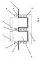
- thermoforming device which has a thermoforming tool 3 with several thermoforming chambers 10. According to the invention, this thermoforming tool is cooled, wherein the cooling in the present case takes place through bore 2, through which a cooling medium is passed. Above the thermoforming tool 3 is to be deformed film web 1, which is clamped between the thermoforming tool 3 and a clamping frame 4. The clamping frame 4 is also coolable in the present case by means of the bore 5, through which a coolant is guided. Above the film web 1 are heating plates 7, which are shown as raised by the double arrows 6, raised or lowered. The skilled person knows that the thermoforming tool 3 is also vertically movable.
- FIG. 2 shows the heating of the clamped between the clamping frame 4 and the thermoforming mold 3 film web 1.
- the heating plates 7 were lowered so that they are preferably in contact with the film web.
- the film web is warmed up until it has the desired temperature in the region of the hot plate.
- the heating is timed.
- thermoforming chambers 10 are subjected to vacuum, with which the film web is deformed as shown. During the entire heating and deep drawing process, the thermoforming tool and the clamping frame are cooled.
- thermoforming tool 3 is lowered so that the packaging trays 8 escape from the thermoforming mold 3.
- the thermoforming tool is lowered so far that the produced packaging troughs can be transported out of the deep drawing area and a renewed deformation of the foil web 1 can take place.
- FIG. 5 the finished packaging troughs are shown. Due to the cooling of the deep-drawing mold, the package edges 9 and / or the bottom of the package are straight because the film web does not shrink after deep-drawing or only very slightly after or during deep-drawing.
- FIG. 6 shows the thermoforming device for the production of deep-drawn Kunststoffoffverpackungsmulden of shrinkable films from a shrinkable film web.
- the device 12 has a lower tool 3 and an upper tool 19.
- the lower tool 3 has the negative of the shape of the packaging tray to be produced.
- In the lower tool channels 2 are incorporated, circulates through which a coolant with which the lower tool is cooled.
- the lower tool is lowered or raised.
- the film web not shown, extends.
- the upper tool 19 is also raised or lowered.
- the clamping frame 4 also has channels 2, through which a coolant circulates, so that the frame of the clamping frame 4 can be cooled.
- the cooling of the clamping frame has the particular advantage that the film web, which is located under the clamping frame is not heated and thus is free of stress.
- the top film will later be sealed to this area. Because this area is tension-free, the sealing of the packaging resulting later on has a very high tightness.
- the device according to the invention has a heating element 7 per packaging tray to be produced. With these heating elements, the film web is heated as quickly as possible. In order to improve the heat transfer between the film web and the respective heating means, an overpressure can be generated in the region under the film web, which presses the film web against the heating means and thus improves the heat transfer.
- thermoforming mold is cooled, so that the film web is cooled during and / or immediately after deep drawing. This cooling takes place until the film web has reached a temperature at which an unwanted reverse deformation of the packaging tray due to the shrinkability of the film can be excluded.
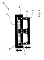
- FIG. 7 shows the sealing device 13 according to the invention, which consists of an upper tool 60 and a lower tool 30.
- the sealing device is part of a packaging machine. Between the upper and the lower tool are the upper film 14 (not shown) and the shrinkable film web 1 (not shown), have been incorporated into the packaging trays 8 by deep drawing arranged.
- the top film 14 is also shrinkable in the present case.
- the film web 1 is fixed and transported by two chains (not shown) in a packaging machine (not shown).
- the top film 14 is sealed to the film web 1 in order to close the packaging troughs 8.
- the upper film 14 is not fixed by chains or the like and is known to be transported by its connection with the lower film 1. As shown by the double arrow, the upper tool is vertically displaceable.
- the heated sealing frame 40 is arranged, which is pressed against the sealing glasses 50 during sealing. As a result, the film webs 1, 14 are pressed against each other. As a result of the resulting pressure and the elevated temperature, the sealing of the top film takes place at the edge of the packaging troughs 8.
- a cooling plate 20 is arranged on the top die, which prevents the top film from heating up outside the seal. This embodiment is of particular interest in shrinkable overfill.
- the cooling plates 20 are also vertically displaceable.
- the lower tool is also vertically veschiebbar, as indicated by the double arrow. Also, the lower tool is cooled in the present case to prevent unwanted shrinkage of the packaging tray during sealing. In the event that the top film is not shrinkable, can usually be dispensed with the cooling plate 20 and a cooling of the upper tool 60.
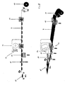
- FIG. 8 shows a packaging machine for producing a shrinkplate, ie a package with a shrinkable packaging tray, which is closed with a non-shrinkable relatively rigid lidding film.
- a shrinkplate ie a package with a shrinkable packaging tray
- the deep-drawing device 12 packaging trays 8 are formed in the film web.
- These packaging troughs 8 are then filled with a packaged product, not shown, and then sealed in the sealing station 13 with a lidding film 14.
- the film web 11 consists of a shrinkable film while the film web 14 is not shrinkable and relatively rigid, so that it acts like a tray.
- the packaging tray is shrunk in a shrinking device 15, wherein only the thermoformed packaging tray with a hot medium, such as hot air, steam or water comes into contact.
- a hot medium such as hot air, steam or water comes into contact.
- the shrunken packaging thus completed is then singulated with the separating device 16 and transported away as a finished package 17.
- the respective double arrows show that one or two units of the respective station can be raised or lowered.
- FIG. 9 shows a packaging machine for making a shrinkpack in two views.
- a shrinkpack consists of a shrinkable upper and a shrinkable lower film.
- the shrinkable film web is unrolled from a roll 11 and formed in a forming station 12, the packaging trays 8 in the film web by deep drawing.
- the packaging tray is sealed with a film web 14 in the sealing station 13 by sealing.
- the lidding film is also a shrinkable film.
- the packages are singulated in a cutting station 16.
- the packages 18 produced in this way are shrunk into a shrinking tunnel in which they are subjected to boiling water from all sides.
- the respective double arrows show that one or two units of the respective station can be raised or lowered.
Landscapes
- Engineering & Computer Science (AREA)
- Mechanical Engineering (AREA)
- Blow-Moulding Or Thermoforming Of Plastics Or The Like (AREA)
- Containers And Plastic Fillers For Packaging (AREA)
- Wrappers (AREA)
- Laminated Bodies (AREA)
- Auxiliary Devices For And Details Of Packaging Control (AREA)
- Closing Of Containers (AREA)
- Moulds For Moulding Plastics Or The Like (AREA)
- Containers Having Bodies Formed In One Piece (AREA)
- Basic Packing Technique (AREA)
- Lining Or Joining Of Plastics Or The Like (AREA)
Description
- Die vorliegende Vorrichtung betrifft eine Verpackungsmaschine aufweisend eine Vorrichtung zur Herstellung einer tiefgezogenen Kunststoffverpackungsmulde und einer Siegelvorrichtung zum Siegeln einer Oberfolie auf die Verpackungsmulde, wobei mindestens die Verpackungsmulde aus einer schrumpffähigen Kunststofffolie gefertigt ist, sowie ein Verfahren zum Herstellen von Verpackungen mit mindestens einer Schrumpffolie.
- Lebensmittel werden heutzutage immer öfter in Kunststoffverpackungen angeboten, die aus einer Verpackungsmulde, in die die Lebensmittel eingelegt werden und einer Oberfolie, mit der die Verpackungsmulde verschlossen wird, bestehen. Derartige Verpackungen werden mit Vorrichtungen und Verfahren hergestellt, wie sie beispielsweise aus der den Oberbegriffen der Ansprüche 1 und 20 entsprechenden
WO 2004/000650 bekannt sind. Die Verpackungsmulden werden in der Regel durch Tiefziehen aus einer planen Folienbahn hergestellt. Bei einigen Verpackungen ist entweder die Folienbahn, in die die Verpackungsmulde eingeformt wurde, und/oder die Oberfolie eine sogenannte Schrumpffolie, d. h. eine Folie, die unter Temperatureinwirkung schrumpft. Diese Verpackungen haben den Vorteil, dass die verpackten Lebensmittel von der Verpackung sehr eng umschlossen werden. Bei diesen Verpackungen wird erst die Oberfolie mit der Folienbahn, aus der die Verpackungsmulde tiefgezogen worden ist, verbunden, bevor die Schrumpfung erfolgt. In der Vergangenheit sind die Verpackungsmulden oftmals unkontrolliert rückgeschrumpft und/oder die Schrumpfung wurde schon durch das Siegelwerkzeug aktiviert, so dass die Schrumpfung dadurch meist unkontrolliert war. - Es war deshalb die Aufgabe der vorliegenden Erfindung, eine Verpackungsmaschine zur Verfügung zu stellen, mit der die Probleme des vorliegenden Standes der Technik behoben werden können.
- Gelöst wird die Aufgabe mit einer Verpackungsmaschine gemäß Anspruch 1
- Es war für den Fachmann überaus erstaunlich und nicht zu erwarten, dass sich mit einer derartigen Verpackungsmaschine Verpackungsmulden mit geraden Verpackungsrändem aus einer schrumpffähigen Kunststofffolie herstellen lassen und/oder dass die ungewollte Rückschrumpfung der hergestellten Verpackungsmulde unmittelbar nach dem Tiefziehen zumindest vermindert ist. Dadurch lassen sich Verpackungsbehälter mit einer ganz neuen Erscheinungsform und einer sehr reproduzierbaren Größe herstellen. Des weiteren war es überaus erstaunlich und nicht zu erwarten, dass es mit der Siegelvorrichtung der erfindungsgemäßen Verpackungsmaschine gelingt, eine unkontrollierte Schrumpfung der Verpackungsmude oder der Oberfolie beim Siegeln zu vermeiden. Die erfindungsgemäße Verpackungsmaschine ist einfach und kostengünstig herzustellen und zu betreiben.
- Eine schrumpffähige Folie im Sinne der Erfindung ist eine thermoformbare, vorzugsweise tiefziehfähige Mehrschichtfolie mit einer Wärmeschrumpffähigkeit in Längs- und in Querrichtung von jeweils wenigstens 20%, wobei die Wärmeschrumpffähigkeit durch Thermoformung im wesentlichen nicht beeinflusst wird. Bevorzugt beträgt die Wärmeschrumpffähigkeit der erfindungsgemäßen Mehrschichtfolien in Längs- und in Querrichtung jeweils wenigstens 25%, bevorzugter wenigstens 30%, noch bevorzugter wenigstens 35%, am bevorzugtesten wenigstens 40% und insbesondere wenigstens 45%. Derartige Folien werden beispielsweise in der
DE 10 2005 017 937.1 offenbart. - Erfindungsgemäß weist die Verpackungsmaschine ein Tiefziehwerkzeug auf, das beim Tiefziehen gekühlt ist. Vorzugsweise weist das Tiefziehwerkzeug dafür Kühlmittel auf. Derartige Kühlmittel können beispielsweise Kühlleitungen sein, die im Bereich des Tiefziehwerkzeugs angeordnet sind und durch die ein Kühlmedium, beispielsweise eine Kühlflüssigkeit oder ein Kühlgas, zirkuliert.
- Vorzugsweise weist die Tiefziehvorrichtung Haltemittel auf, so dass die Folie zwischen dem Haltemittel und dem Tiefziehwerkzeug einspannbar ist. Vorzugsweise handelt es sich bei dem Haltemittel um einen Klemmrahmen. Vorzugsweise ist das Haltemittel vertikal verschiebbar angeordnet. Vorzugsweise wird die Folienbahn mit - dem Haltemittel fixiert bevor das Tiefziehen erfolgt. In einer bevorzugten Ausführungsform der vorliegenden Erfindung ist dieses Haltemittel ebenfalls mit einem Kühlmittel versehen, das an denselben Kühlmittelkreislauf wie das Tiefziehwerkzeug oder an einen anderen Kühlkreislauf angeschlossen sein kann. Als Kühlmittel eignet sich insbesondere Wasser oder ein Kühlmittel, das beispielsweise auch in Kühlschränken und dergleichen Anwendung findet. Diese bevorzugte Ausführungsform der vorliegenden Erfindung hat den Vorteil, dass der Bereich der Verpackungsmulde, an den in einem weiteren Verfahrensschritt eine Deckelfolie gesiegelt wird, keine oder nur sehr geringe Spannungen aufweist, was in weniger Leckagen im Bereich der Siegelnaht resultiert.
- Vorzugsweise ist mindestens ein Kühlmittelkreislauf geregelt, beispielsweise temperaturgeregelt, so dass das Tiefziehwerkzeug und/oder das Haltemittel immer eine nahezu konstante Temperatur aufweist.
- Weiterhin bevorzugt weist die Tiefziehvorrichtung ein Heizmittel, besonders bevorzugt eine Heizplatte auf, mit der die Folienbahn insbesondere vor dem Tiefziehen aufheizbar ist. Mit dem Heizmittel wird die Folienbahn zumindest bereichsweise bis zur Plastifizierungstemperatur erwärmt. Vorzugsweise erfolgt die Erwärmung sehr schnell. Besonders bevorzugt weist die Tiefziehvorrichtung Mittel auf, mit denen der Kontakt und damit der Wärmeübergang zwischen der Folienbahn und dem Heizmittel verbessert wird. Besonders bevorzugt wird dieser Kontakt durch unter- und/oder Überdruck verbessert, der die Foliebahn an die Heizmittel saugt und/oder drückt. Für den Fall, dass mehrere Verpackungsmulden gleichzeitig hergestellt werden, weist die erfindungsgemäße Vorrichtung vorzugsweise pro herzustellende Verpackungsmulde ein Heizmittel auf. Vorzugsweise sind die Heizmittel vertikal verschiebbar, an und abschaltbar und/oder Temperatur-regelbar. Nachdem die Foliebahn erwärmt worden ist und besonders bevorzugt vor dem Tiefziehen wird das Heizmittel wieder von der Folienbahn entfernt und/oder abgeschaltet, um eine Überhitzung der Folienbahn zu vermeiden und um zu verhindern, dass bei der Kühlung des Tiefziehwerkzeuges beziehungsweise des Haltemittels zu viel Wärme abgeführt werden muss. Das Heizmittel kann jedoch auch als Tiefziehstempel eingesetzt werden. Vorzugsweise erfolgt die Erwärmung lokal sehr gezielt und sehr schnell, so dass nur die gewünschten Bereiche erwärmt werden. Nach oder beim Tiefziehen wird die Folienbahn dann möglichst schnell abgekühlt, um eine ungewollte Rückverformung der thermogeformten Verpackungsmulden zu vermeiden. Der Fachmann erkennt, dass die Erwärmung und Kühlung auch gleichzeitig erfolgen kann, um zu vermeiden, dass sich gewisse Bereiche der Folienbahn während deren Erwärmung miterwärmen und/oder um eine unerwünschte Aufwärmung dieser Bereiche zu vermindern und/oder um eine ungewollte Rückverformung zu vermeiden.
- In einer weiteren bevorzugten Ausführungsform der vorliegenden Erfindung weist die erfindungsgemäße Verpackungsmaschine Vakuum- und/oder Druckmittel auf, mit dem die Folienbahn in das Tiefziehwerkzeug hineingedrückt bzw. hineingezogen wird und dabei seine abschließende Form erhält bzw. um den Wärmeübergang zwischen der Folienbahn und dem Tiefziehwerkzeug zu verbessern. Dieselben oder andere Vakuum- und/oder Druckmittel können auch dafür herangezogen werden, um den Kontakt zwischen der unverformten Folienbahn und dem Heizmittel zu verbessern.
- Weiterhin weist die Verpackungsmaschine eine Siegelvorrichtung auf. Die Siegelvorrichtung dient zum Siegeln einer Oberfolie auf eine Verpackungsmulde, wobei die Verpackungsmulde und/oder die Deckelfolie aus einer schrumpffähigen Folie gefertigt sind.
- In der Regel wird die Verpackungsmulde durch Tiefziehen in eine Folienbahn eingeformt. Der Fachmann versteht, dass auch die Oberfolie, die auf die Verpackungsmulde gesiegelt wird, tiefgezogen sein kann.
- Mit der erfindungsgemäßen Verpackungsmaschine können Verpackungen aus einer schrumpffähigen Verpackungsmulde und einer schrumpffähigen Oberfolie hergestellt werden. Solche Verpackungen werden als Skrinkpack bezeichnet. Die Oberfolie kann jedoch auch aus einer nicht schrumpffähige Folienbahn, beispielsweise aus einer geschäumten Polyolefin oder geschäumten Polyester sein. Solche Verpackungen werden als Shrinkplate bezeichnet.
- Die Siegelvorrichtung der erfindungsgemäßen Verpackungsmaschine weist ein Unterwerkzeug und ein Oberwerkzeug auf, wobei sich das Unterwerkzeug unterhalb und sich das Oberwerkzeug oberhalb der Folienbahnen, die miteinander verbunden werden, befindet. Das Unterwerkzeug und das Oberwerkzeug werden zum Siegeln der Oberfolie an die Unterfolie gegeneinander gepresst. Dabei erfolgt die Siegelung der beiden Folienbahnen aneinander unter Temperatureinfluß. Erfindungsgemäß ist das Unterwerkzeug und/oder das Oberwerkzeug gekühlt. Diese Kühlung kann beispielsweise durch Zirkulation eines Kühlmediums durch Kanäle, die in das Unter- und/oder das Oberwerkzeug eingearbeitet sind, erfolgen. Als Kühlmedium eignet sich Wasser oder die von Kühlschränken bekannten Medien. Vorzugsweise erfolgt die Kühlung der Oberfolie und/oder der Verpackungsmulden so, dass kein unkontrollierter Schrumpf der jeweiligen Folie einsetzt, d.h. die Temperatur der jeweiligen Folienbahn darf die Temperatur, bei der der Schrumpf einsetzt nie erreichen oder überschreiten.
- Vorzugsweise ist zumindest das Unterwerkzeug, besonders bevorzugt auch das Oberwerkzeug vertikal verschiebbar.
- Weiterhin bevorzugt weist das Ober oder das Unterwerkzeug ein Siegelmittel, beispielsweise einen Siegelrahmen, auf, das(der) beheizt ist. Die Beheizung erfolgt in der Regel durch eine elektrische Beheizung. Die Beheizung sollte bei der vorliegenden Erfindung vorteilhafterweise auf das Siegelmittel beschränkt sein, damit eine unnötige Kühlung des jeweiligen Werkzeugs nicht vonnöten ist.
- An dem Werkzeug, das den Siegelrahmen nicht aufweist, ist vorzugsweise eine Siegelbrille angeordnet. Vorzugsweise weist die Siegelbrille eine Gummigegenlage auf. Weiterhin bevorzugt ist die Siegelbrille gekühlt und besonders bevorzugt ebenfalls vertikal verschiebbar.
- Das Oberwerkzeug ist vorzugsweise vertikal verschieblich angeordnet. Weiterhin bevorzugt ist das Oberwerkzeug gekühlt, um zu vermeiden, dass es sich mit der Zeit aufheizt und dadurch eine ungewollte Schrumpfung der Oberfolie bewirkt. Diese Ausführungsform ist insbesondere dann von Vorteil, wenn die Oberfolie eine Schrumpffolie ist.
- Vorzugsweise weist die Siegelvorrichtung eine Kühlplatte auf, die besonders bevorzugt im Bereich der Oberfolie angeordnet ist. Diese Kühlplatte ist vorzugsweise ebenfalls vertikal verschiebbar angeordnet. Für den Fall, dass die Oberfolie an mehrere Verpackungsmulden gleichzeitig gesiegelt wird, ist vorzugsweise im Bereich jeder Verpackungsmulde jeweils eine Kühlplatte angeordnet.
- Als Verpackungsmaschine kommt jede dem Fachmann geläufige Verpackungsmaschine in Frage. Vorzugsweise handelt es sich um eine sogenannte Form-Fill-Seal-Verpackungsmaschine.
- Ein weiterer Gegenstand der vorliegenden Erfindung ist ein Verfahren gemäß Anspruch 20
- Die folgenden Ausführungen gelten für beide erfindungsgemäße Verfahren.
- Es war für den Fachmann überaus erstaunlich und nicht zu erwarten, dass sich mit einem derartigen Verfahren Verpackungsmulden mit geraden Rändern herstellern lassen und/oder dass keine ungewollte Schrumpfung nach dem Tiefziehen erfolgt. Dadurch lassen sich Verpackungsbehälter mit einer ganz neuen Erscheinungsform und einer sehr reproduzierbaren Größe herstellen. Mit den erfindungsgemäßen Verfahren wird verhindert, dass eine ungewolltes, von dem Siegelwerkzeug initiiertes Schrumpfen der Schrumpffolie erfolgt.
- Vorzugsweise wird die Folienbahn vor dem Tiefziehen eingespannt. Vorzugsweise erfolgt das Einspannen der Folienbahn mit einem Klemmrahmen. Besonders bevorzugt ist dieser Klemmrahmen gekühlt und am meisten bevorzugt vertikal verschiebbar angeordnet. Ein gekühlter Klemmrahmen hat den Vorteil, dass der spätere Siegelbereich zumindest nahezu spannungsfrei ist, was zu weniger Leckagen im Siegelbreich führt.
- Weiterhin bevorzugt wird die Folienbahn vor dem Tiefziehen aufgewärmt. Vorzugsweise erfolgt das Aufwärmen und Kühlen zeitlich versetzt, wobei das Aufwärmen vorzugsweise vor dem Kühlen erfolgt. Weiterhin bevorzugt wird eine Oberfläche der Folienbahn aufgewärmt und die gegenüberliegende Oberfläche gekühlt. In einer weiteren bevorzugten Ausführungsform der vorliegenden Erfindung erfolgt das Erwärmen und Kühlen gleichzeitig, wobei die Folienbahn bereichsweise aufgewärmt und abgekühlt wird. Besonders bevorzugt wird die Folienbahn in Richtung der Aufheiz- bzw. Abkühlmittel gedrückt oder gesaugt, um einen möglichst guten Wärmeübergang zu erzielen. Für den Fall, dass mehrere Verpackungsmulden gleichzeitig hergestellt werden, wird jeder herzustellenden Verpackungsmulde vorzugsweise ein Heizmittel zugeordnet. Dadurch kann die benötigte Wärme lokal sehr gezielt in die Folienbahn eingebracht werden.
- Das Tiefziehen kann auf jede dem Fachmann geläufige Art und Weise erfolgen. Vorzugsweise erfolgt das Tiefziehen jedoch durch Über- und/oder Unterdruck (Vakuum). Weiterhin bevorzugt erfolgt das Tiefziehen mit einem Stempel oder das Tiefziehen wird mit einem Stempel unterstützt, wobei der Stempel und das Heizmittel ein Bauteil sein können.
- Erfindungsgemäß wird die Folienbahn zumindest bereichsweise vorm, beim und/oder nach dem Tiefziehen gekühlt. Insbesondere der Bereich der tiefgezogen worden ist, wird beim und/oder nach dem Tiefziehen so lange gekühlt, bis keine ungewollte Rückverformung des tiefgezogenen Bereichs mehr erfolgt. In der Regel ist dies bei Temperaturen unterhalb der Plastifizierungstemperatur der jeweiligen Folie gegeben.
- Vorzugsweise wird das der Schrumpffolie zugewandte Siegelwerkzeug gekühlt. Diese Ausführungsform des erfindungsgemäßen Verfahrens hat den Vorteil, dass das der Schrumpffolie zugewandte Werkzeug ein Schrumpfen der Schrumpffolie nicht ungewollt aktiviert. Beim Einsatz von zwei schrumpffähigen Folien werden vorzugsweise beide Werkzeuge gekühlt
- Vorzugsweise wird zumindest die schrumpffähige Folienbahn vorm und/oder beim Siegeln fixiert. Vorzugsweise erfolgt das Fixieren mit den Siegelwerkzeugen. Weiterhin bevorzugt erfolgt das Fixieren der schrumpffähigen Folienbahn mit den Ketten, mit denen die Folienbahn entlang der Verpackungsmaschine transportiert wird.
- Im Folgenden wird die Erfindung anhand der
Figuren 1 bis 9 erläutert. Dieses Erläuterungen sind lediglich beispielhaft und schränken den allgemeinen Erfindungsgedanken nicht ein. Die Erläuterungen gelten für die erfindungsgemäße Vorrichtung, die erfindungsgemäße Verpackung.sowie das erfindungsgemäße Verfahren gleichermaßen. -
Figur 1 zeigt die Tiefziehvorrichtung vor dem Tiefziehen. -
Figur 2 zeigt das Erwärmen der Folienbahn. -
Figur 3 zeigt das Tiefziehen der Verpackungsmulde. -
Figur 4 zeigt das Lösen der Halterung. -
Figur 5 zeigt die resultierende Verpackungsmulde. -
Figur 6 zeigt die Tiefziehvorrichtung -
Figur 7 zeigt die Siegelvorrichtung -
Figur 8 zeigt eine Verpackungsmaschine zur Herstellung eines shrinkplate -
Figur 9 zeigt eine Verpackungsmaschine zur Herstellung eines shrinkpacks - In
Figur 1 ist die Tiefziehvorrichtung dargestellt, die ein Tiefziehwerkzeug 3 mit mehreren Tiefziehkammern 10 aufweist. Erfindungsgemäß ist dieses Tiefziehwerkzeug gekühlt, wobei die Kühlung in dem vorliegenden Fall durch Bohrung 2 erfolgt, durch die ein Kühlmedium geführt wird. Oberhalb des Tiefziehwerkzeuges 3 befindet sich die zu verformende Folienbahn 1, die zwischen dem Tiefziehwerkzeug 3 und einem Klemmrahmen 4 eingespannt ist. Der Klemmrahmen 4 ist in dem vorliegenden Fall mittels der Bohrung 5, durch die ein Kühlmittel geführt wird, ebenfalls kühlbar. Oberhalb der Folienbahn 1 befinden sich Heizplatten 7, die wie durch die Doppelpfeile 6 dargestellt, anhebbar bzw. absenkbar sind. Der Fachmann weiß, dass das Tiefziehwerkzeug 3 ebenfalls vertikal bewegbar ist. -
Figur 2 zeigt das Erwärmen der zwischen dem Klemmrahmen 4 und dem Tiefziehwerkzeug 3 eingespannten Folienbahn 1. Dafür wurden die Heizplatten 7 abgesenkt, so dass sie vorzugsweise in Kontakt mit der Folienbahn stehen. Die Folienbahn wird solange aufgewärmt, bis sie im Bereich der Wärmeplatte die gewünschte Temperatur aufweist. Vorzugsweise erfolgt die Erwärmung zeitgesteuert. - Sobald die Folie hinreichend erwärmt wurde, werden die Heizplatten wieder angehoben und das Tiefziehen der Folienbahn 1 zur Herstellung der Verpackungsmulden 8 erfolgt (
Fig. 3 ). In dem vorliegenden Fall sind die Tiefziehkammern 10 mit Vakuum beaufschlagbar, mit dem die Folienbahn wie dargestellt verformt wird. Während des gesamten Aufheiz- und Tiefziehprozesses werden das Tiefziehwerkzeug und der Klemmrahmen gekühlt. - Sobald die Verpackungsmulden 8 tiefgezogen sind (
Figur 4 ), wird das Tiefziehwerkzeug 3 abgesenkt, so dass sich die Verpackungsmulden 8 aus dem Tiefziehwerkzeug 3 entformen. Das Tiefziehwerkzeug wird soweit abgesenkt, dass die hergestellten Verpackungsmulden aus dem Tiefziehbereich heraustransportiert werden können und eine neuerliche Verformung der Folienbahn 1 erfolgen kann. - In
Figur 5 sind die fertiggestellten Verpackungsmulden dargestellt. Durch die Kühlung der Tiefziehform sind die Packungsränder 9 und/oder der Boden der Verpackung gerade, weil die Folienbahn nach dem Tiefziehen gar nicht oder nur sehr wenig nach oder beim Tiefziehen schrumpft. -
Figur 6 zeigt die Tiefziehvorrichtung zur Herstellung von tiefgezogenen Kunstoffverpackungsmulden aus schrumpffähigen Folien aus einer schrumpffähigen Folienbahn. Die Vorrichtung 12 weist ein Unterwerkzeug 3 und ein Oberwerkzeug 19 auf. Das Unterwerkzeug 3 weist das Negativ der Form der herzustellenden Verpackungsmulde auf. In das Unterwerkzeug sind Kanäle 2 eingearbeitet, durch die ein Kühlmittel zirkuliert mit dem das Unterwerkzeug gekühlt wird. Wie durch den Doppelpfeil angedeutet, ist das Unterwerkzeug absenkbar bzw. anhebbar. Zwischen dem Unterwerkzeug und dem Oberwerkzeug verläuft die nicht dargestellte Folienbahn. Das Oberwerkzeug 19 ist ebenfalls anhebbar bzw. absenkbar. Dasselbe gilt für den Klemmrahmen 4 und die Heizmittel 7. Mit dem Klemmrahmen wird die Folienbahn gegen das Unterwerkzeug gedrückt und festgeklemmt, damit sie tiefgezogen werden kann. Der Klemmrahmen 4 weist darüber hinaus auch Kanäle 2 auf, durch die ein Kühlmittel zirkuliert, so dass der Rahmen der Klemmrahmen 4 kühlbar ist. Die Kühlung des Klemmrahmens hat insbesondere den Vorteil, dass sich die Folienbahn, die sich unter dem Klemmrahmen befindet nicht erwärmt wird und somit spannungsfrei ist. An diesen Bereich wird später die Oberfolie gesiegelt. Dadurch dass dieser Bereich spannungsfrei ist, weist die Siegelung der später resultierenden Verpackung eine sehr hohe Dichtigkeit auf. Die erfindungsgemäße Vorrichtung weist pro herzustellender Verpackungsmulde ein Heizelement 7 auf. Mit diesen Heizelementen wird die Folienbahn möglichst schnell erwärmt. Um den Wärmeübergang zwischen der Folienbahn und der jeweiligen Heizmitteln zu verbessert, kann in dem Bereich unter der Folienbahn ein Überdruck erzeugt werden, der die Folienbahn gegen das Heizmittel drückt und damit den Wärmeübergang verbessert. Der Fachmann erkennt, dass auch zwischen der Folienbahn und dem Heizmittel 7 ein Unterdruck erzeugt werden kann, der die Folienbahn gegen das Heizmittel saugt. Sobald die Folienbahn ihre Plastifizierungstemperatur erreicht hat, wird sie mit den Heizmitteln 7, die dann gleichzeitig als Stempel wirken in die jeweilige Tiefziehform gedrückt und/oder es wird in der Tiefziehform ein Unterdruck angelegt, der die Folienbahn in die Tiefziehform hineinsaugt. Diese Tiefziehform ist gekühlt, so dass die Folienbahn beim und/oder unmittelbar nach dem Tiefziehen gekühlt wird. Diese Kühlung erfolgt so lange bis die Folienbahn eine Temperatur erreicht hat, bei der eine ungewollte Rückverformung der Verpackungsmulde aufgrund der Schrumpffähigkeit der Folie ausgeschlossen werden kann. -
Figur 7 zeigt die erfindungsgemäße Siegelvorrichtung 13, die aus einem Oberwerkzeug 60 und einem Unterwerkzeug 30 besteht. Die Siegelvorrichtung ist Teil einer Verpackungsmaschine. Zwischen dem Ober und dem Unterwerkzeug sind die Oberfolie 14 (nicht dargestellt) sowie die schrumpffähige Folienbahn 1 (nicht dargestellt), in die Verpackungsmulden 8 durch Tiefziehen eingearbeitet worden sind, angeordnet. Die Oberfolie 14 ist in dem vorliegenden Fall ebenfalls schrumpffähig. Die Folienbahn 1 wird durch zwei Ketten (nicht dargestellt) in einer Verpackungsmaschine (nicht dargestellt) fixiert und transportiert Die Oberfolie 14 wird an die Folienbahn 1 gesiegelt, um die Verpackungsmulden 8 zu verschließen. Die Oberfolie 14 ist nicht durch Ketten oder dergleichen fixiert und wird bekanntermaßen durch ihre Verbindung mit der Unterfolie 1 transportiert. Wie durch den Doppelpfeil dargestellt, ist das Oberwerkzeug vertikal verschiebbar. An dem Oberwerkzeug ist der beheizte Siegelrahmen 40 angeordnet, der beim Siegeln gegen die Siegelbrille 50 gedrückt wird. Dadurch werden die Folienbahnen 1, 14 gegeneinander gepresst. Durch den dabei entstehenden Druck und die erhöhte Temperatur erfolgt die Siegelung der Oberfolie an den Rand der Verpackungsmulden 8. Im Bereich jeder Verpackungsmulde ist am Oberwerkzeug eine Kühlplatte 20 angeordnet, die ein Aufwärmen der Oberfolie außerhalb der Siegelung verhindert. Diese Ausführungsform ist insbesondere bei schrumpffähigen Oberfollen von Interesse. Die Kühlplatten 20 sind ebenfalls vertikal verschiebbar. Das Unterwerkzeug ist auch, wie durch den Doppelpfeil angedeutet vertikal veschiebbar. Auch das Unterwerkzeug ist in dem vorliegenden Fall gekühlt, um ein ungewolltes Schrumpfen der Verpackungsmulde beim Siegeln zu verhindern. Für den Fall, dass die Oberfolie nicht schrumpffähig ist, kann in der Regel auf die Kühlplatte 20 und eine Kühlung des Oberwerkzeugs 60 verzichtet werden. -
Figur 8 zeigt eine Verpackungsmaschinen zur Herstellung einer shrinkplate, d.h. einer Verpackung mit einer schrumpffähigen Verpackungsmulde, die mit einer nicht schrumpffähigen vergleichsweise starren Deckelfolie verschlossen ist. Von einer Rolle 11 wird taktweise eine Folienbahn abgerollt und in der Tiefziehvorrichtung 12 werden Verpackungsmulden 8 in die Folienbahn eingeformt. Diese Verpackungsmulden 8 werden dann mit einem nicht dargestellten Verpackungsgut gefüllt und danach in der Siegelstation 13 mit einer Deckelfolie 14 verschlossen. In dem vorliegenden Fall besteht die Folienbahn 11 aus einer schrumpffähigen Folie während die Folienbahn 14 nicht schrumpffähig und relativ starr ist, so dass sie wie eine Tablett wirkt. Nach dem Siegeln wird die Verpackungsmulde in einer Schrumpfvorrichtung 15 geschrumpft, wobei nur die tiefgezogene Verpackungsmulde mit einem heißen Medium, beispielsweise heiße Luft, Dampf oder Wasser in Berührung kommt. Die so fertiggestellten geschrumpften Verpackungen werden so dann mit der Scheidvorrichtung 16 vereinzelt und als fertiggestellte Verpackung 17 abtransportiert. Die jeweiligen Doppelpfeile zeigen, dass ein oder zwei Aggregate der jeweiligen Station anhebbar bzw. absenkbar sind. -
Figur 9 zeigt eine Verpackungsmaschine zur Herstellung einer shrinkpack in zwei Ansichten. Ein shrinkpack besteht aus einer schrumpffähigen Ober- und einer schrumpffähigen Unterfolie. Wiederum wird von einer Rolle 11 die schrumpffähigen Folienbahn abgerollt und in einer Formstation 12 die Verpackungsmulden 8 in die Folienbahn durch Tiefziehen eingeformt. Nachdem die Verpackungsmulden mit einem nicht dargestellten Verpackungsgut befüllt worden sind, wird die Verpackungsmulde mit einer Folienbahn 14 in der Siegelstation 13 durch Siegeln verschlossen. In dem vorliegenden Fall handelt es sich bei der Deckelfolie ebenfalls um eine schrumpffähige Folie. In einem nächsten Verfahrensschritt werden die Verpackungen in einer Schneidstation 16 vereinzelt. Die so hergestellten Verpackungen 18 werden in einen Schrumpftunnel geschrumpft, in dem sie von allen Seiten mit kochendem Wasser beaufschlagt werden. Die jeweiligen Doppelpfeile zeigen, dass ein oder zwei Aggregate der jeweiligen Station anhebbar bzw. absenkbar sind. -
- 1
- Folienbahn
- 2
- Kühlmittel, Kühlplatte
- 3
- Unterwerkzeug, Tiefziehwerkzeug
- 4
- Siegelrahmen, Haltemittel, Klemmmittel
- 5
- Siegelbrille, kühlmittel
- 6
- Oberwerkzeug, Boden der Verpackungsmulde, Doppelpfeil
- 7
- Heizmittel, Heizplatten, Heizelemnt, Heizpatrone
- 8
- Verpackungsmulde
- 9
- Packungsränder
- 10
- Packungsboden
- 11
- Folienrolle
- 12
- Tiefziehstation
- 13
- Siegelstation, Siegelvorrichtung
- 14
- Oberfolie
- 15
- Schrumpfstation, Schrumpftunnel
- 16
- Schneidstation
- 17
- Fertiggestellte, geschrumpfte Verpackung
- 18
- Verpackung vor dem Schrumpfen
- 19
- Oberwerkzeug
Claims (28)
- Verpackungsmaschine zur Herstellung einer Verpackung mit einem Tiefziehwerkzeug (3) zur Herstellung von tiefgezogenen Verpackungsmulden aus einer schrumpffähigen Folienbahn sowie mit einer Siegelvorrichtung mit einem Unterwerkzeug (30) und einem Oberwerkzeug (60), zur Siegelung einer schrumpffähigen Oberfolie an die Verpackungsmulden, dadurch gekennzeichnet, dass das Tiefziehwerkzeug (3) beim Tiefziehen und das Unterwerkzeug (30) und/oder das Oberwerkzeug (60) beim Siegeln gekühlt sind.
- Verpackungsmaschine nach Anspruch 1, dadurch gekennzeichnet, dass das Unterwerkzeug (30) ein Kühlmittel aufweist.
- Verpackungsmaschine nach einem der voranstehenden Ansprüche, dadurch gekennzeichnet, dass das Unterwerkzeug (30) vertikal verschiebbar ist.
- Verpackungsmaschine nach einem der voranstehenden Ansprüche, dadurch gekennzeichnet, dass es Siegelmittel (40) aufweist, die beheizbar sind.
- Verpackungsmaschine nach einem der voranstehenden Ansprüche, dadurch gekennzeichnet, dass das Oberwerkzeug (60) eine Kühlplatte (20) aufweist.
- Verpackungsmaschine nach Anspruch 5, dadurch gekennzeichnet, dass das Oberwerkzeug eine Kühlplatte (20) pro herzustellender Verpackung (17, 18) aufweist.
- Verpackungsmaschine nach einem der voranstehenden Ansprüche, dadurch gekennzeichnet, dass das Oberwerkzeug (60) und/oder die Kühlplatten (20) vertikal verschiebbar angeordnet ist(sind).
- Verpackungsmaschine nach einem der voranstehenden Ansprüche, dadurch gekennzeichnet, dass es eine Siegelbrille (50) aufweist, die vorzugsweise an dem Unterwerkzeug (30) angeordnet ist.
- Verpackungsmaschine nach Anspruch 8, dadurch gekennzeichnet, dass die Siegelbrille (50) gekühlt ist.
- Verpackungsmaschine nach Anspruch 8 oder 9, dadurch gekennzeichnet, dass die Siegelbrille (50) anheb- und absenkbar ist.
- Verpackungsmaschine nach einem der Ansprüche 8-10, dadurch gekennzeichnet, dass die Siegelbrille (50) eine Gummigegenlage aufweist.
- Verpackungsmaschine nach einem der voranstehenden Ansprüche, dadurch gekennzeichnet, dass das Tiefziehwerkzeug (3) Kühlmittel (2) aufweist.
- Verpackungsmaschine nach einem der voranstehenden Ansprüche, dadurch gekennzeichnet, dass die Folienbahn (1) zwischen einem Haltemittel (4) und dem Tiefziehwerkzeug (3) einspannbar ist.
- Verpackungsmaschine nach Anspruch 13, dadurch gekennzeichnet, dass Haltemittel (4) mit Kühlmitteln (5) kühlbar ist.
- Verpackungsmaschine nach Anspruch 13 oder 14, dadurch gekennzeichnet, dass das Haltemittel (4) vertikal verschiebbar angeordnet ist.
- Verpackungsmaschine nach einem der voranstehenden Ansprüche, dadurch gekennzeichnet, dass das Tiefziehwerkzeug ein Heizmittel (7), vorzugsweise eine Heizplatte, aufweist, mit der die Folienbahn aufheizbar ist
- Verpackungsmaschine nach Anspruch 16, dadurch gekennzeichnet, dass die Heizplatte (7) als Tiefziehstempel ausgeführt ist.
- Verpackungsmaschine nach einem der voranstehenden Ansprüche, dadurch gekennzeichnet, dass das Tiefziehwerkzeug Vakuum- und/oder Druckmittel zum Tiefziehen der Folienbahn aufweist.
- Verpackungsmaschine nach einem der voranstehenden Ansprüche, dadurch gekennzeichnet, dass das Tiefziehwerkzeug das Vakuum- und/oder Druckmittel aufweist um den Kontakt zwischen der Foliebahn und dem Heizmittel (7) zu verbessern.
- Verfahren zur Herstellung einer Verpackung durch Siegeln einer Oberfolie (14) auf eine Verpackungsmulde, wobei mindestens die Verpackungsmulde (8) aus einer schrumpffähigen Kunststofffolie (1) hergestellt wird und die Verpackungsmulde (8) einen Siegelbereich aufweist, dadurch gekennzeichnet, dass die Folienbahn (1) erst teilweise aufgeheizt und der Siegelbereich vom und beim Tiefziehen teilweise gekühlt wird und dass beim Siegeln der Oberfolie (14) auf die Verpackungsmulde (8) die Oberfolie (14) und/oder die Verpackungsmulde (8) gekühlt wird.
- Verfahren nach Anspruch 20, dadurch gekennzeichnet, dass der Wärmeeintrag für die Siegelung in einem Oberwerkzeug (60) erfolgt.
- Verfahren nach einem der voranstehenden Ansprüche, dadurch gekennzeichnet, dass die schrumpffähige Kunststofffolie vorzugsweise von Siegelwerkzeugen (60, 30) fixiert wird.
- Verfahren nach einem der voranstehenden Ansprüche, dadurch gekennzeichnet, dass die schrumpffähigen Kunststofffolie von Transportketten fixiert wird
- Verfahren nach einem der voranstehenden Ansprüche, dadurch gekennzeichnet, dass die Verpackung nach dem Siegeln geschrumpft wird.
- Verfahren nach einem der voranstehenden Ansprüche, dadurch gekennzeichnet, dass die Folienbahn (1) vor dem Tiefziehen eingespannt wird.
- Verfahren nach einem der voranstehenden Ansprüche, dadurch gekennzeichnet, dass die Folienbahn (1) durch Über- und/oder Unterdruck verformt wird.
- Verfahren nach einem der voranstehenden Ansprüche, dadurch gekennzeichnet, dass das jeder Verpackungsmulde (8) ein Heizmittel (7) zugeordnet wird.
- Verfahren nach einem der voranstehenden Ansprüche, dadurch gekennzeichnet, dass die tiefgezogene Folie (1) so lange gekühlt wird, bis eine Rückverformung unterbleibt.
Priority Applications (1)
| Application Number | Priority Date | Filing Date | Title |
|---|---|---|---|
| PL06707349T PL1855946T3 (pl) | 2005-03-01 | 2006-03-01 | Pakowarka i sposób wytwarzania obkurczających opakowań |
Applications Claiming Priority (4)
| Application Number | Priority Date | Filing Date | Title |
|---|---|---|---|
| DE200510009870 DE102005009870A1 (de) | 2005-03-01 | 2005-03-01 | Vorrichtung zur Herstellung von tiefgezogenen Verpackungsmulden mit einem gekühlten Formuntereil |
| DE102005009868A DE102005009868A1 (de) | 2005-03-01 | 2005-03-01 | Siegeln von Schrumpffolien |
| DE200510017937 DE102005017937A1 (de) | 2005-04-18 | 2005-04-18 | Thermoformbares Verpackungsmaterial mit Schrumpfeigenschaften |
| PCT/EP2006/001869 WO2006092289A1 (de) | 2005-03-01 | 2006-03-01 | Verpackungsmaschine zur herstellung von schrumpffähigen verpackungen |
Publications (2)
| Publication Number | Publication Date |
|---|---|
| EP1855946A1 EP1855946A1 (de) | 2007-11-21 |
| EP1855946B1 true EP1855946B1 (de) | 2009-10-21 |
Family
ID=36250772
Family Applications (3)
| Application Number | Title | Priority Date | Filing Date |
|---|---|---|---|
| EP06707349A Expired - Lifetime EP1855946B1 (de) | 2005-03-01 | 2006-03-01 | Verpackungsmaschine zur herstellung von schrumpffähigen verpackungen |
| EP06707350.2A Revoked EP1855947B1 (de) | 2005-03-01 | 2006-03-01 | Thermoformbares verpackungsmaterial mit schrumpfeigenschaften |
| EP06707348A Revoked EP1855945B1 (de) | 2005-03-01 | 2006-03-01 | Vorrichtung zur herstellung von tiefgezogenen verpackungsmulden mit einem gekühlten formunterteil |
Family Applications After (2)
| Application Number | Title | Priority Date | Filing Date |
|---|---|---|---|
| EP06707350.2A Revoked EP1855947B1 (de) | 2005-03-01 | 2006-03-01 | Thermoformbares verpackungsmaterial mit schrumpfeigenschaften |
| EP06707348A Revoked EP1855945B1 (de) | 2005-03-01 | 2006-03-01 | Vorrichtung zur herstellung von tiefgezogenen verpackungsmulden mit einem gekühlten formunterteil |
Country Status (11)
| Country | Link |
|---|---|
| US (3) | US20090000252A1 (de) |
| EP (3) | EP1855946B1 (de) |
| JP (3) | JP2008531343A (de) |
| AT (2) | ATE446252T1 (de) |
| AU (3) | AU2006219995A1 (de) |
| BR (3) | BRPI0607563A2 (de) |
| DE (2) | DE502006005185D1 (de) |
| ES (3) | ES2325743T3 (de) |
| NO (3) | NO20074496L (de) |
| PL (2) | PL1855947T3 (de) |
| WO (3) | WO2006092290A2 (de) |
Families Citing this family (22)
| Publication number | Priority date | Publication date | Assignee | Title |
|---|---|---|---|---|
| DE102005017755A1 (de) | 2005-04-15 | 2006-10-19 | Cfs Germany Gmbh | Verpackungsmaschine zur Herstellung von Verpackungen mit einem Transponder |
| US7665281B2 (en) | 2005-07-13 | 2010-02-23 | Cfs Germany Gmbh | Machine for making packaging with form-fit connection |
| JP4918645B2 (ja) * | 2006-05-23 | 2012-04-18 | ニュー クリア システムズ リミテッド | ラミネート製品 |
| DE102006040526A1 (de) | 2006-08-30 | 2008-03-06 | Cfs Kempten Gmbh | Thermoformbares Verpackungsmaterial mit Schrumpfeigenschaften |
| ES2349481T5 (es) | 2007-05-04 | 2017-11-15 | Gea Food Solutions Germany Gmbh | Máquina de empaquetar con detección de sustancias extrañas |
| DE102008045547A1 (de) | 2008-09-03 | 2010-03-04 | Ccl Label Meerane Gmbh | Etikett, insbesondere für einen Mehrwegbehälter |
| US8171703B2 (en) * | 2009-06-09 | 2012-05-08 | General Mills Marketing, Inc. | Method for packaging products by employing positive pressure differential |
| US20100307948A1 (en) * | 2009-06-09 | 2010-12-09 | Domingues David J | Packaging employing both shrinkable and non-shrinkable films |
| US20100310732A1 (en) * | 2009-06-09 | 2010-12-09 | Domingues David J | Pressure packaged dough products |
| DE102009041563A1 (de) * | 2009-09-15 | 2011-03-24 | Multivac Sepp Haggenmüller Gmbh & Co. Kg | Verpackungsmaschine mit mehreren Heizelementen |
| JP2014533612A (ja) * | 2011-11-30 | 2014-12-15 | 株式会社クレハ | 熱収縮性多層フィルム及びその製造方法 |
| WO2013083834A1 (de) * | 2011-12-09 | 2013-06-13 | Gea Cfs Germany Gmbh | Verpackungsmaschine mit einem kombinierten form- und siegelwerkzeug |
| DE102012102410A1 (de) * | 2012-03-21 | 2013-09-26 | Mondi Consumer Packaging Technologies Gmbh | Trayverpackung für Lebensmittel |
| ES2655280T5 (es) | 2013-12-16 | 2021-11-03 | Cryovac Inc | Aparato de embalaje de un producto |
| KR101598526B1 (ko) * | 2014-04-25 | 2016-03-02 | (주)대한기계 | 진공 포장장치 |
| EP3087974A1 (de) * | 2015-04-29 | 2016-11-02 | Rodos BioTarget GmbH | Gezielte nanoträger zur gezielten verabreichung von therapeutika für die gentherapie |
| EP3645419A1 (de) | 2017-06-29 | 2020-05-06 | Cryovac, LLC | Verwendung von zweifach ofentauglichen polyesterfolien in wärmeformungsverpackungsanwendungen und daraus erhaltene, zweifach ofentaugliche wärmegeformte verpackungen |
| CN107160660A (zh) * | 2017-07-07 | 2017-09-15 | 深圳市亚美三兄吸塑有限公司 | 碳纤维产品的模压成型方法及模具 |
| DE102018204044A1 (de) * | 2018-03-16 | 2019-09-19 | Multivac Sepp Haggenmüller Se & Co. Kg | Tiefziehverpackungsmaschine mit Folienumlenkung |
| ES2912663T3 (es) * | 2018-06-11 | 2022-05-26 | Multivac Haggenmueller Kg | Embalaje de película así como procedimiento y estación de sellado para la fabricación de un embalaje de película |
| CN110171609B (zh) * | 2019-04-18 | 2020-12-29 | 长沙理工大学 | 一种面筋制品生产工艺中的自动包装设备及包装方法 |
| EP4426535A1 (de) * | 2021-11-05 | 2024-09-11 | Gea Food Solutions Germany GmbH | Verpackungsmaschine mit einem gekühlten formwerkzeug |
Citations (1)
| Publication number | Priority date | Publication date | Assignee | Title |
|---|---|---|---|---|
| WO2004000650A1 (de) * | 2002-06-20 | 2003-12-31 | Multivac Sepp Haggenmüller Gmbh & Co. Kg | Verfahren und vorrichtung zum verpacken |
Family Cites Families (43)
| Publication number | Priority date | Publication date | Assignee | Title |
|---|---|---|---|---|
| US1319082A (en) * | 1919-10-21 | hulbert | ||
| US1709196A (en) * | 1926-02-16 | 1929-04-16 | Snyder Vernon Charles | Method of applying covers to containers |
| US2331472A (en) * | 1943-05-14 | 1943-10-12 | Joseph J Holleck | Combination filing cabinet and desk unit |
| DE1145087B (de) * | 1956-10-02 | 1963-03-07 | Herbert William Brock | Maschine zum Verpacken von Stueckware, insbesondere Biskuits und anderen Lebensmitteln, in schrumpfbare Behaelter |
| US3054679A (en) * | 1959-04-22 | 1962-09-18 | Kenneth C Bradford | Food package |
| US3076299A (en) * | 1961-02-13 | 1963-02-05 | Lerner Philip | Packaging apparatus |
| US3340714A (en) * | 1963-11-19 | 1967-09-12 | Bell Telephone Labor Inc | Method for deforming metal-plastic laminates |
| US3561057A (en) * | 1967-06-05 | 1971-02-09 | Robert L Butzko | Apparatus for the production of formed articles from plastic sheet material |
| US3972155A (en) * | 1969-09-24 | 1976-08-03 | Mahaffy & Harder Engineering Company | Packaging techniques for semi-rigid packages |
| US3792181A (en) * | 1969-09-24 | 1974-02-12 | Mahaffy & Harder Eng Co | Semi-rigid plastic package with reclosable seal |
| US3661484A (en) * | 1970-02-12 | 1972-05-09 | Mahaffy & Harder Eng Co | Automatic container making apparatus |
| US3642411A (en) * | 1970-05-26 | 1972-02-15 | Anderson Bros Mfg Co | Thermoforming apparatus for moving sheet material |
| US3706174A (en) * | 1971-03-03 | 1972-12-19 | Grace W R & Co | Packaging machine and method of forming packages |
| US3754372A (en) * | 1971-10-26 | 1973-08-28 | Grace W R & Co | Apparatus for making thermoplastic vacuum packages |
| US3760563A (en) * | 1971-12-13 | 1973-09-25 | G Zimmermann | Drawing apparatus for sealing containers |
| US3958394A (en) * | 1972-01-12 | 1976-05-25 | Mahaffy & Harder Engineering Company | Continuous movement packaging machine |
| US3815322A (en) * | 1972-05-08 | 1974-06-11 | I Wyslotsky | Packaging machine |
| US4062718A (en) * | 1976-09-02 | 1977-12-13 | The Dow Chemical Company | Heat sealing means |
| DE2843166A1 (de) * | 1978-10-04 | 1980-04-24 | Dixie Union Verpackungen Gmbh | Vakuumverpackungsmaschine |
| US4229927A (en) * | 1978-10-06 | 1980-10-28 | J. Sainsbury Limited | Process and apparatus for vacuum packing |
| NL189499C (nl) | 1978-12-18 | 1993-05-03 | Asahi Chemical Ind | Werkwijze voor het vervaardigen van een vel of film, alsmede verpakking. |
| US4440824A (en) * | 1981-10-23 | 1984-04-03 | Composite Container Corporation | Thermoformable coextruded multilayered structure |
| FR2528386B1 (fr) * | 1982-06-14 | 1986-04-11 | Erca Holding | Procede et installation de conditionnement d'un produit |
| GB2137931B (en) * | 1983-04-07 | 1987-02-04 | Grace W R & Co | Laminated packaging film heat-shrinkable after forming, and method for the preparation thereof |
| IT1183203B (it) * | 1984-02-07 | 1987-10-15 | Gabler Gmbh Maschbau | Dispositivo per produrre parti imbutite di materia artificale termoplastica nonche'procedimento attuato con detto dispositivo |
| DE3446650A1 (de) * | 1984-12-20 | 1986-06-26 | Multivac Sepp Haggenmüller KG, 8941 Wolfertschwenden | Verpackungsmaschine |
| US4878826A (en) * | 1987-12-07 | 1989-11-07 | Wendt Michael L | Apparatus for thermoforming plastic materials |
| DE3925746C2 (de) * | 1989-08-03 | 1994-06-23 | Multivac Haggenmueller Kg | Verfahren und Vorrichtung zum Herstellen einer wiederverschließbaren Packung |
| US5023121A (en) * | 1990-04-12 | 1991-06-11 | W. R. Grace & Co.-Conn. | Coextruded film with peelable sealant |
| US5280434A (en) * | 1991-07-01 | 1994-01-18 | Thermoforming Technologies, Inc. | Heating system for thermoforming |
| US5404693A (en) * | 1992-04-17 | 1995-04-11 | Sencorp Systems, Inc. | Method for making plastic blister packages |
| EP0597502B1 (de) | 1992-11-13 | 2005-03-16 | Cryovac, Inc. | Wärmeschrumpfbare, durch Single-site-Katalyse hergestellte Copolymere enthaltende Folien. |
| JP3051614B2 (ja) * | 1993-09-29 | 2000-06-12 | 三菱樹脂株式会社 | 深絞り成形用共押出複合フィルム |
| US5834077A (en) | 1994-10-04 | 1998-11-10 | W. R. Grace & Co.-Conn. | High shrink multilayer film which maintains optics upon shrinking |
| US5633022A (en) * | 1995-06-08 | 1997-05-27 | Old Line Plastics, Inc. | Differential temperature vacuum-forming tool |
| NZ338086A (en) | 1998-10-08 | 2000-07-28 | Viskase Corp | Biaxially stretched, heat shrinkable polymeric film comprising three copolymers, blends and process for foods |
| AUPR082700A0 (en) | 2000-10-17 | 2000-11-09 | Sporos Sa | Cook-in film |
| DE10145413A1 (de) * | 2001-09-14 | 2005-06-09 | Focke Gmbh & Co. Kg | Verfahren zum Identifizieren von Gegenständen sowie Gegenstand mit elektronischem Datenträger |
| JP4471562B2 (ja) | 2002-09-26 | 2010-06-02 | 株式会社クレハ | 深絞り包装方法 |
| US20040070504A1 (en) * | 2002-10-14 | 2004-04-15 | Brollier Brian W. | Semi-covert RFID enabled containers |
| EP1566265A1 (de) | 2004-02-20 | 2005-08-24 | Flexopack S.A. Plastics Industry | Styrolpolymer oder eine Mischung von Styrolpolymeren enthaltende mehrschichtige wärmeschrumpfbare Folie |
| US20070138192A1 (en) * | 2005-07-13 | 2007-06-21 | Dietmar Send | Packaging with subsequently molded form-fit connection |
| US7665281B2 (en) * | 2005-07-13 | 2010-02-23 | Cfs Germany Gmbh | Machine for making packaging with form-fit connection |
-
2006
- 2006-03-01 BR BRPI0607563-0A patent/BRPI0607563A2/pt not_active Application Discontinuation
- 2006-03-01 EP EP06707349A patent/EP1855946B1/de not_active Expired - Lifetime
- 2006-03-01 AU AU2006219995A patent/AU2006219995A1/en not_active Abandoned
- 2006-03-01 JP JP2007557417A patent/JP2008531343A/ja not_active Withdrawn
- 2006-03-01 JP JP2007557416A patent/JP2008531420A/ja active Pending
- 2006-03-01 WO PCT/EP2006/001870 patent/WO2006092290A2/de not_active Ceased
- 2006-03-01 US US11/817,196 patent/US20090000252A1/en not_active Abandoned
- 2006-03-01 DE DE502006005185T patent/DE502006005185D1/de not_active Expired - Lifetime
- 2006-03-01 WO PCT/EP2006/001869 patent/WO2006092289A1/de not_active Ceased
- 2006-03-01 PL PL06707350T patent/PL1855947T3/pl unknown
- 2006-03-01 EP EP06707350.2A patent/EP1855947B1/de not_active Revoked
- 2006-03-01 BR BRPI0607405-7A patent/BRPI0607405A2/pt not_active IP Right Cessation
- 2006-03-01 AU AU2006219996A patent/AU2006219996A1/en not_active Abandoned
- 2006-03-01 ES ES06707348T patent/ES2325743T3/es not_active Expired - Lifetime
- 2006-03-01 US US11/817,202 patent/US20090007524A1/en not_active Abandoned
- 2006-03-01 BR BRPI0607584-3A patent/BRPI0607584A2/pt not_active IP Right Cessation
- 2006-03-01 AT AT06707349T patent/ATE446252T1/de active
- 2006-03-01 AT AT06707348T patent/ATE433916T1/de active
- 2006-03-01 PL PL06707349T patent/PL1855946T3/pl unknown
- 2006-03-01 EP EP06707348A patent/EP1855945B1/de not_active Revoked
- 2006-03-01 ES ES06707350T patent/ES2425043T3/es not_active Expired - Lifetime
- 2006-03-01 DE DE502006003993T patent/DE502006003993D1/de not_active Expired - Lifetime
- 2006-03-01 JP JP2007557415A patent/JP2008531342A/ja active Pending
- 2006-03-01 US US11/817,278 patent/US20080152772A1/en not_active Abandoned
- 2006-03-01 AU AU2006219997A patent/AU2006219997A1/en not_active Abandoned
- 2006-03-01 ES ES06707349T patent/ES2332940T3/es not_active Expired - Lifetime
- 2006-03-01 WO PCT/EP2006/001868 patent/WO2006092288A1/de not_active Ceased
-
2007
- 2007-09-04 NO NO20074496A patent/NO20074496L/no not_active Application Discontinuation
- 2007-09-05 NO NO20074502A patent/NO20074502L/no not_active Application Discontinuation
- 2007-09-27 NO NO20074909A patent/NO20074909L/no not_active Application Discontinuation
Patent Citations (1)
| Publication number | Priority date | Publication date | Assignee | Title |
|---|---|---|---|---|
| WO2004000650A1 (de) * | 2002-06-20 | 2003-12-31 | Multivac Sepp Haggenmüller Gmbh & Co. Kg | Verfahren und vorrichtung zum verpacken |
Also Published As
Similar Documents
| Publication | Publication Date | Title |
|---|---|---|
| EP1855945B1 (de) | Vorrichtung zur herstellung von tiefgezogenen verpackungsmulden mit einem gekühlten formunterteil | |
| DE69309185T2 (de) | Presse zum Formen eines Gegenstandes aus Verbundmaterial mit verstärkenden Fasern in einer Polimermatrix | |
| EP2070687B1 (de) | Verpackungsmaschine mit Induktionsheizung | |
| EP2788259B1 (de) | Verpackungsmaschine mit einem kombinierten form- und siegelwerkzeug | |
| WO2007090654A1 (de) | Verpackungsmaschine für die herstellung einer verpackung mit einem rücksprung in dem verpackungsmuldenrand | |
| DE102012018974B4 (de) | Tiefziehverpackungsmaschine mit Stempelformung | |
| DE102009047151B3 (de) | Siegelstation | |
| DE69713127T2 (de) | Verfahren und formwerkzeuge zum spritzgiessen eines teils aus plastikmaterial in ein verpackungsblattmaterial | |
| DE2106725A1 (de) | Verfahren und Vorrichtung zum Herstellen von Behaltern aus thermoplastischen Kunst stoffolien | |
| DE3446650A1 (de) | Verpackungsmaschine | |
| EP0557614A1 (de) | Verfahren zum Verschweissen von halogenfreien Thermoplastfolien | |
| DE10257144A1 (de) | Verfahren und Vorrichtung zum Tiefziehen verformbarer Materialien | |
| DE19737503B4 (de) | Thermoformmaschine | |
| EP3446989B1 (de) | Verpackungsmaschine zur herstellung einer mehrlagenpackung | |
| EP2905232A1 (de) | Siegelwerkzeugoberteil einer Schalenverschließmaschine und entsprechendes Verfahren | |
| EP1497101A2 (de) | Verfahren und vorrichtung zum tiefziehen verformbarer materialien sowie bef llen des ausgeformten k rpers | |
| DE4135935C2 (de) | Verfahren und Vorrichtung zum taktweisen Thermoverformen von Kunststoffolie im Endlosband | |
| DE102021124720A1 (de) | Formstation für eine Tiefziehverpackungsmaschine, Tiefziehverpackungsmaschine, deren Verwendung sowie Verfahren zum Tiefziehen einer Kunststofffolie | |
| DE112016006715T5 (de) | Vorrichtung, Formaufbau und Verfahren zum Thermoformen eines Produkts aus einem Kunststofffilm | |
| CH620647A5 (en) | Process and device for packaging commodity articles in vacuum packs | |
| DE102005009870A1 (de) | Vorrichtung zur Herstellung von tiefgezogenen Verpackungsmulden mit einem gekühlten Formuntereil | |
| EP2097321A1 (de) | Verpackungsmaschine mit einem mittel zum kühlen einer folienbahn vor dem tiefziehen | |
| DE10214714A1 (de) | Verfahren und Vorrichtung zum Tiefziehen verformbarer Materialien | |
| WO2023078918A1 (de) | Verpackungsmaschine mit einem gekühlten formwerkzeug | |
| WO2025247488A1 (de) | Verfahren und vorrichtung zum erwärmen einer folie sowie dazugehörige thermoformanlage |
Legal Events
| Date | Code | Title | Description |
|---|---|---|---|
| PUAI | Public reference made under article 153(3) epc to a published international application that has entered the european phase |
Free format text: ORIGINAL CODE: 0009012 |
|
| 17P | Request for examination filed |
Effective date: 20071001 |
|
| AK | Designated contracting states |
Kind code of ref document: A1 Designated state(s): AT BE BG CH CY CZ DE DK EE ES FI FR GB GR HU IE IS IT LI LT LU LV MC NL PL PT RO SE SI SK TR |
|
| 17Q | First examination report despatched |
Effective date: 20080311 |
|
| DAX | Request for extension of the european patent (deleted) | ||
| GRAP | Despatch of communication of intention to grant a patent |
Free format text: ORIGINAL CODE: EPIDOSNIGR1 |
|
| GRAS | Grant fee paid |
Free format text: ORIGINAL CODE: EPIDOSNIGR3 |
|
| GRAA | (expected) grant |
Free format text: ORIGINAL CODE: 0009210 |
|
| AK | Designated contracting states |
Kind code of ref document: B1 Designated state(s): AT BE BG CH CY CZ DE DK EE ES FI FR GB GR HU IE IS IT LI LT LU LV MC NL PL PT RO SE SI SK TR |
|
| REG | Reference to a national code |
Ref country code: GB Ref legal event code: FG4D Free format text: NOT ENGLISH |
|
| REG | Reference to a national code |
Ref country code: CH Ref legal event code: EP |
|
| REG | Reference to a national code |
Ref country code: IE Ref legal event code: FG4D |
|
| REF | Corresponds to: |
Ref document number: 502006005185 Country of ref document: DE Date of ref document: 20091203 Kind code of ref document: P |
|
| REG | Reference to a national code |
Ref country code: ES Ref legal event code: FG2A Ref document number: 2332940 Country of ref document: ES Kind code of ref document: T3 |
|
| LTIE | Lt: invalidation of european patent or patent extension |
Effective date: 20091021 |
|
| REG | Reference to a national code |
Ref country code: PL Ref legal event code: T3 |
|
| PG25 | Lapsed in a contracting state [announced via postgrant information from national office to epo] |
Ref country code: PT Free format text: LAPSE BECAUSE OF FAILURE TO SUBMIT A TRANSLATION OF THE DESCRIPTION OR TO PAY THE FEE WITHIN THE PRESCRIBED TIME-LIMIT Effective date: 20100222 Ref country code: IS Free format text: LAPSE BECAUSE OF FAILURE TO SUBMIT A TRANSLATION OF THE DESCRIPTION OR TO PAY THE FEE WITHIN THE PRESCRIBED TIME-LIMIT Effective date: 20100221 Ref country code: FI Free format text: LAPSE BECAUSE OF FAILURE TO SUBMIT A TRANSLATION OF THE DESCRIPTION OR TO PAY THE FEE WITHIN THE PRESCRIBED TIME-LIMIT Effective date: 20091021 Ref country code: LT Free format text: LAPSE BECAUSE OF FAILURE TO SUBMIT A TRANSLATION OF THE DESCRIPTION OR TO PAY THE FEE WITHIN THE PRESCRIBED TIME-LIMIT Effective date: 20091021 Ref country code: SE Free format text: LAPSE BECAUSE OF FAILURE TO SUBMIT A TRANSLATION OF THE DESCRIPTION OR TO PAY THE FEE WITHIN THE PRESCRIBED TIME-LIMIT Effective date: 20091021 |
|
| REG | Reference to a national code |
Ref country code: IE Ref legal event code: FD4D |
|
| PG25 | Lapsed in a contracting state [announced via postgrant information from national office to epo] |
Ref country code: SI Free format text: LAPSE BECAUSE OF FAILURE TO SUBMIT A TRANSLATION OF THE DESCRIPTION OR TO PAY THE FEE WITHIN THE PRESCRIBED TIME-LIMIT Effective date: 20091021 Ref country code: LV Free format text: LAPSE BECAUSE OF FAILURE TO SUBMIT A TRANSLATION OF THE DESCRIPTION OR TO PAY THE FEE WITHIN THE PRESCRIBED TIME-LIMIT Effective date: 20091021 |
|
| REG | Reference to a national code |
Ref country code: SK Ref legal event code: T3 Ref document number: E 6907 Country of ref document: SK |
|
| PG25 | Lapsed in a contracting state [announced via postgrant information from national office to epo] |
Ref country code: RO Free format text: LAPSE BECAUSE OF FAILURE TO SUBMIT A TRANSLATION OF THE DESCRIPTION OR TO PAY THE FEE WITHIN THE PRESCRIBED TIME-LIMIT Effective date: 20091021 Ref country code: IE Free format text: LAPSE BECAUSE OF FAILURE TO SUBMIT A TRANSLATION OF THE DESCRIPTION OR TO PAY THE FEE WITHIN THE PRESCRIBED TIME-LIMIT Effective date: 20091021 Ref country code: DK Free format text: LAPSE BECAUSE OF FAILURE TO SUBMIT A TRANSLATION OF THE DESCRIPTION OR TO PAY THE FEE WITHIN THE PRESCRIBED TIME-LIMIT Effective date: 20091021 Ref country code: BG Free format text: LAPSE BECAUSE OF FAILURE TO SUBMIT A TRANSLATION OF THE DESCRIPTION OR TO PAY THE FEE WITHIN THE PRESCRIBED TIME-LIMIT Effective date: 20100121 Ref country code: EE Free format text: LAPSE BECAUSE OF FAILURE TO SUBMIT A TRANSLATION OF THE DESCRIPTION OR TO PAY THE FEE WITHIN THE PRESCRIBED TIME-LIMIT Effective date: 20091021 |
|
| PLBE | No opposition filed within time limit |
Free format text: ORIGINAL CODE: 0009261 |
|
| STAA | Information on the status of an ep patent application or granted ep patent |
Free format text: STATUS: NO OPPOSITION FILED WITHIN TIME LIMIT |
|
| PGFP | Annual fee paid to national office [announced via postgrant information from national office to epo] |
Ref country code: SK Payment date: 20100301 Year of fee payment: 5 |
|
| 26N | No opposition filed |
Effective date: 20100722 |
|
| BERE | Be: lapsed |
Owner name: CFS GERMANY G.M.B.H. Effective date: 20100331 |
|
| PG25 | Lapsed in a contracting state [announced via postgrant information from national office to epo] |
Ref country code: GR Free format text: LAPSE BECAUSE OF FAILURE TO SUBMIT A TRANSLATION OF THE DESCRIPTION OR TO PAY THE FEE WITHIN THE PRESCRIBED TIME-LIMIT Effective date: 20100122 Ref country code: MC Free format text: LAPSE BECAUSE OF NON-PAYMENT OF DUE FEES Effective date: 20100331 |
|
| PG25 | Lapsed in a contracting state [announced via postgrant information from national office to epo] |
Ref country code: BE Free format text: LAPSE BECAUSE OF NON-PAYMENT OF DUE FEES Effective date: 20100331 |
|
| REG | Reference to a national code |
Ref country code: SK Ref legal event code: MM4A Ref document number: E 6907 Country of ref document: SK Effective date: 20110301 |
|
| PG25 | Lapsed in a contracting state [announced via postgrant information from national office to epo] |
Ref country code: SK Free format text: LAPSE BECAUSE OF NON-PAYMENT OF DUE FEES Effective date: 20110301 |
|
| PG25 | Lapsed in a contracting state [announced via postgrant information from national office to epo] |
Ref country code: CY Free format text: LAPSE BECAUSE OF FAILURE TO SUBMIT A TRANSLATION OF THE DESCRIPTION OR TO PAY THE FEE WITHIN THE PRESCRIBED TIME-LIMIT Effective date: 20091021 |
|
| PG25 | Lapsed in a contracting state [announced via postgrant information from national office to epo] |
Ref country code: LU Free format text: LAPSE BECAUSE OF NON-PAYMENT OF DUE FEES Effective date: 20100301 Ref country code: HU Free format text: LAPSE BECAUSE OF FAILURE TO SUBMIT A TRANSLATION OF THE DESCRIPTION OR TO PAY THE FEE WITHIN THE PRESCRIBED TIME-LIMIT Effective date: 20100422 |
|
| PG25 | Lapsed in a contracting state [announced via postgrant information from national office to epo] |
Ref country code: TR Free format text: LAPSE BECAUSE OF FAILURE TO SUBMIT A TRANSLATION OF THE DESCRIPTION OR TO PAY THE FEE WITHIN THE PRESCRIBED TIME-LIMIT Effective date: 20091021 |
|
| PGFP | Annual fee paid to national office [announced via postgrant information from national office to epo] |
Ref country code: GB Payment date: 20140423 Year of fee payment: 9 |
|
| PGFP | Annual fee paid to national office [announced via postgrant information from national office to epo] |
Ref country code: FR Payment date: 20140416 Year of fee payment: 9 Ref country code: CZ Payment date: 20140424 Year of fee payment: 9 |
|
| PG25 | Lapsed in a contracting state [announced via postgrant information from national office to epo] |
Ref country code: CZ Free format text: LAPSE BECAUSE OF NON-PAYMENT OF DUE FEES Effective date: 20150301 |
|
| GBPC | Gb: european patent ceased through non-payment of renewal fee |
Effective date: 20150301 |
|
| REG | Reference to a national code |
Ref country code: FR Ref legal event code: ST Effective date: 20151130 |
|
| PG25 | Lapsed in a contracting state [announced via postgrant information from national office to epo] |
Ref country code: GB Free format text: LAPSE BECAUSE OF NON-PAYMENT OF DUE FEES Effective date: 20150301 |
|
| PG25 | Lapsed in a contracting state [announced via postgrant information from national office to epo] |
Ref country code: FR Free format text: LAPSE BECAUSE OF NON-PAYMENT OF DUE FEES Effective date: 20150331 |
|
| PGFP | Annual fee paid to national office [announced via postgrant information from national office to epo] |
Ref country code: PL Payment date: 20160222 Year of fee payment: 11 |
|
| PG25 | Lapsed in a contracting state [announced via postgrant information from national office to epo] |
Ref country code: PL Free format text: LAPSE BECAUSE OF NON-PAYMENT OF DUE FEES Effective date: 20170301 |
|
| PGFP | Annual fee paid to national office [announced via postgrant information from national office to epo] |
Ref country code: AT Payment date: 20230317 Year of fee payment: 18 |
|
| PGFP | Annual fee paid to national office [announced via postgrant information from national office to epo] |
Ref country code: DE Payment date: 20230320 Year of fee payment: 18 |
|
| PGFP | Annual fee paid to national office [announced via postgrant information from national office to epo] |
Ref country code: NL Payment date: 20230322 Year of fee payment: 18 |
|
| P01 | Opt-out of the competence of the unified patent court (upc) registered |
Effective date: 20230526 |
|
| PGFP | Annual fee paid to national office [announced via postgrant information from national office to epo] |
Ref country code: IT Payment date: 20230331 Year of fee payment: 18 Ref country code: ES Payment date: 20230414 Year of fee payment: 18 Ref country code: CH Payment date: 20230402 Year of fee payment: 18 |
|
| REG | Reference to a national code |
Ref country code: DE Ref legal event code: R119 Ref document number: 502006005185 Country of ref document: DE |
|
| REG | Reference to a national code |
Ref country code: CH Ref legal event code: PL |
|
| REG | Reference to a national code |
Ref country code: NL Ref legal event code: MM Effective date: 20240401 |
|
| REG | Reference to a national code |
Ref country code: AT Ref legal event code: MM01 Ref document number: 446252 Country of ref document: AT Kind code of ref document: T Effective date: 20240301 |
|
| PG25 | Lapsed in a contracting state [announced via postgrant information from national office to epo] |
Ref country code: NL Free format text: LAPSE BECAUSE OF NON-PAYMENT OF DUE FEES Effective date: 20240401 |
|
| PG25 | Lapsed in a contracting state [announced via postgrant information from national office to epo] |
Ref country code: NL Free format text: LAPSE BECAUSE OF NON-PAYMENT OF DUE FEES Effective date: 20240401 |
|
| PG25 | Lapsed in a contracting state [announced via postgrant information from national office to epo] |
Ref country code: DE Free format text: LAPSE BECAUSE OF NON-PAYMENT OF DUE FEES Effective date: 20241001 |
|
| PG25 | Lapsed in a contracting state [announced via postgrant information from national office to epo] |
Ref country code: AT Free format text: LAPSE BECAUSE OF NON-PAYMENT OF DUE FEES Effective date: 20240301 |
|
| PG25 | Lapsed in a contracting state [announced via postgrant information from national office to epo] |
Ref country code: DE Free format text: LAPSE BECAUSE OF NON-PAYMENT OF DUE FEES Effective date: 20241001 Ref country code: AT Free format text: LAPSE BECAUSE OF NON-PAYMENT OF DUE FEES Effective date: 20240301 Ref country code: CH Free format text: LAPSE BECAUSE OF NON-PAYMENT OF DUE FEES Effective date: 20240331 |
|
| REG | Reference to a national code |
Ref country code: ES Ref legal event code: FD2A Effective date: 20250425 |
|
| PG25 | Lapsed in a contracting state [announced via postgrant information from national office to epo] |
Ref country code: IT Free format text: LAPSE BECAUSE OF NON-PAYMENT OF DUE FEES Effective date: 20240301 |
|
| PG25 | Lapsed in a contracting state [announced via postgrant information from national office to epo] |
Ref country code: ES Free format text: LAPSE BECAUSE OF NON-PAYMENT OF DUE FEES Effective date: 20240302 |