EP1856979A2 - Système machinal d'enroulement de pâte - Google Patents
Système machinal d'enroulement de pâte Download PDFInfo
- Publication number
- EP1856979A2 EP1856979A2 EP07108377A EP07108377A EP1856979A2 EP 1856979 A2 EP1856979 A2 EP 1856979A2 EP 07108377 A EP07108377 A EP 07108377A EP 07108377 A EP07108377 A EP 07108377A EP 1856979 A2 EP1856979 A2 EP 1856979A2
- Authority
- EP
- European Patent Office
- Prior art keywords
- winding
- dough
- conveying direction
- raising
- riser
- Prior art date
- Legal status (The legal status is an assumption and is not a legal conclusion. Google has not performed a legal analysis and makes no representation as to the accuracy of the status listed.)
- Granted
Links
Images






Classifications
-
- A—HUMAN NECESSITIES
- A21—BAKING; EDIBLE DOUGHS
- A21C—MACHINES OR EQUIPMENT FOR MAKING OR PROCESSING DOUGHS; HANDLING BAKED ARTICLES MADE FROM DOUGH
- A21C3/00—Machines or apparatus for shaping batches of dough before subdivision
- A21C3/06—Machines for coiling sheets of dough, e.g. for producing rolls
Definitions
- the invention relates to a method for producing a wound dough product according to the preamble of claim 1. Furthermore, the invention relates to an arrangement or apparatus for producing wound dough products, which is particularly suitable for carrying out the method, according to the preamble of claim 13. Furthermore, the invention relates to a Lifting or raising device, which is suitable for use in connection with the method or the device according to the preamble of claim 27. Furthermore, the invention relates to a stretching device for extending located on a conveyor base output riser, wherein the stretching device in particular for the implementation of said method or in particular for the said arrangement can be used.
- WO 86/02808 proposed to feed the triangular dough piece with a leading triangle side two pivotally hinged Wickellatten which are spaced apart in dough conveying direction side by side to leave room for the dough piece filling.
- the winding battens have a convex-angled course, which lies opposite the conveyor belt.
- a first section in the dough conveying direction runs obliquely to the conveyor belt, while the second section adjoining at an angle extends parallel to the conveyor belt.
- the oblique portion serves to knock up the leading end edge of the exit riser.
- a corrugation or other roughening on the undersides of the Wickellatten is provided.
- a modification is proposed to the effect that two successive conveyor belts used of which the second with its initial knife edge is positioned slightly higher than that in the conveying direction preceding.
- pressure wheels serve to press the dough piece against the conveyor belt, so that it also gets sufficient thrust in the conveying direction.
- it is proposed in both embodiments to complete the winding by means of a flexible train or a stiff Wickellatte, which each form the end of the winding passage.
- WO 99/49736 in particular FIG. 12 there, are dough elevation means in the form of articulating lever tabs 36, which are articulated pivotably about a transverse to the conveying direction of the articulated axis of the supplied dough piece.
- the free end of the lever tab is designed to raise the leading dough end edge with a protruding to the surface of the conveyor belt 9 hook.
- the actual dough winding takes place on a remotely located, separate winding conveyor 22.
- EP-B-0 673 603 describes an apparatus for winding dough pieces for croissants.
- the winding is also carried out with the aid of a pair of juxtaposed, spaced-apart slats or wound battens with roughened rubber on the undersides to facilitate the dough top-up position, which press or Wickellatten are each adjustable by active drives transverse to the conveying direction.
- the active actuators are part of a control loop and are controlled in connection with a dough sensor.
- an automatic, active adjustment of the respective distance of the press or Teigwickellatten is brought about transversely to the conveying direction.
- the invention is based on the object, in the machine production of coiled dough products, an increase in the speed of the dough wrapping process, in particular during the transition from the initial dough wrapping to achieve curling in itself.
- arrangement or apparatus for producing wound dough products are proposed.
- the general inventive idea includes a lifting and setting device, as indicated in claim 28. With the latter, the functional reliability of the initial dough wrapping can be increased.
- the general inventive idea includes a stretching device for extending on a conveyor base located Kir Suiteen according to independent claim 31.
- the raising means for the leading dough piece edge and the means for winding or rolling the dough piece co-operate with each other in such a way that the respective distance of the raising means and the winding members to the opposite conveyor pad at least temporarily extended becomes.
- the raising means are used as it comes as actuators on arrival of an exit riser or when abutting the exit riser with its leading edge, to put the winding members in position in the sense of an enlarged entrance passage in the winding passage.
- an exit riser hitting the elevating device changes the position or position of the elevating device in the sense of broadening the through-passage to the winding device.
- the adjustment of the lifting device causes the latter a resulting adjustment of the winding device also in the sense of increasing the distance to the conveyor base, resulting in a broadening of the winding passage. This facilitates the picking up and further transporting of the exit riser and the rolling in which is associated with an increasing enlargement of the winding diameter.
- the lifting means or the lifting means are lifted away from the conveyor base with the stop of a dough piece edge, thereby forming a transition to the winding passage.
- the interaction of the invention or the raising means with the or the winding elements can be concretized, for example, to the effect that the one or more upsetting or the subsequent winding members under or raise, resulting in the Hochstell slidegang forms a seamless, edge-free transition to the winding passage.
- Another advantage of the invention is that the or the raising means can immediately fall back into a starting position, which is closer to the conveyor pad. In this initial position, the or the raising means are again ready to capture and lift the next promoted piece of dough on the leading end edge. In this case, the previous piece of dough may still be in the winding passage in the winding process.
- the achievable increase in the dough piece throughput and the production speed due to overlapping dough piece processing is obvious.
- the first and second process phase on a be carried out common conveyor pad, the flowing intertwining of the raising of the dough edge and the rolling up of the dough piece is facilitated. Faulty gaps or edges in the transition from Hochstell trim in the winding passage are avoided.
- the first and the second phase can overlap each other temporally and / or locally, which further promotes the dough piece throughput and the production speed.
- the pivot or rotation axis (in the case of rotating winding members) at To remove the action and / or attachment of the lifting or the lifting means of the conveyor pad or to move at a greater distance.
- This offset of the winding pivot axis which is expediently arranged in the entrance area of the winding passage, creates a free, sufficiently large, problem-free transition or passage to the winding passage for the dough piece already raised at the edge.
- the elevating device is at least partially positioned between the winding means of the conveyor pad or obliquely below the winding device, so that a taking under the Winding device is possible by the adjusted by the incoming exit riser lifting device.
- This gripping is facilitated by bevels, vaults or recesses with which the winding device is designed in its input area or in the engagement area for the lifting device.
- wound dough products with a specific appearance in that prior to entry into the first phase mentioned in claim 1, the starting risers are stretched in the conveying direction and / or widened to the conveying direction.
- stretching in the conveying direction can advantageously create concave inwardly curved side edges, which result after winding over the dough product length changing pitch contour.
- wound dough products with a special appearance for example as Spanish or Italian croissants, can be produced by producing corresponding waisted triangular shapes before wrapping.
- the starting riser stretched in the conveying direction and / or widened transversely to the conveying direction before the entry into the first phase or the starting riser stretched in the conveying direction and / or widened transversely to the conveying direction.
- the side edges running parallel to the conveying direction are concavely curved inward.
- this produces the typical waisted triangular shape for Spanish and Italian croissants.
- the length may be equivalent to the triangle height of a triangular piece of dough which is triangular in shape, with the base forming the leading edge in the conveying direction, preferably in the case of isosceles triangular shapes. This can be realized with the stretching device according to the invention.
- the exit riser is widened by being rolled transversely to the conveying direction. This is particularly effective for dough pieces of triangular basic shape and anticipatory triangle base. With widening of the Triangular base resulting after wrapping the typical for Italian or Spanish croissants slender, long ends.
- the winding device is mounted translationally and / or rotationally deflectable or otherwise floating, advantageously at least in one direction to the conveyor pad to movements to compensate for the increasing Teig Swiss- Winding diameter to perform.
- at least one pivot axis at a distance from the conveyor base and transversely and parallel to the conveying direction is expedient.
- a fiction-specific training in this context is that this pivot axis is subjected to lifting and lowering movements in one direction from and to the conveyor base.
- the elevating device is pivotably articulated on a stationary base, and the winding device is also pivotally connected to the elevating device.
- the rotational or pivot axis of the lifting device is held stationary on a base, and the rotational or pivot axis of the winding device is also articulated via one or more intermediate pivot lever on this base.
- the one or more pivoting lever wins the winding device or its pivot axis one or more additional degrees of freedom for lifting or lowering relative to the conveyor base in coordination with the elevating device. With highs of the edge of the current dough piece leaves create a smooth transition to the winding passage for this.
- the arrangement or device according to the invention is advantageous to form as a built-in or retrofit cassette ("winding cassette"), which can be fastened, for example, via bolt fastenings on the machine frame of the dough processing line.
- the elevating device and the winding device are combined in a separate frame, which in turn can be fastened via said bolt device on the (main) frame of the dough processing line.
- the bolt device can be realized, for example, with draw bolts, via which the winding cassette can be locked and unlocked in the main frame.
- the winding cassette may be provided on its outer sides with carrying handles to increase the handling.
- the winding passage is preceded by a transverse rolling or transverse rolling device acting transversely to the conveying direction, a dough stretching device acting parallel to the conveying direction for lengthening the dough piece geometry and / or a filling and / or moistening station, the dough pieces can be contoured realize.
- the stretching device is used to extend the dough piece in the conveying direction, in particular for extending the triangle height in a dough piece with triangular basic shape and anticipatory Triangular base.
- the cross roll or cross rolling machine widened such a triangle base to give the dough piece slender ends after winding.
- the moistening station is mainly associated with a Teig Glance, so that the dough piece remains closed after winding.
- the reduction of production interruptions due to maintenance, in particular cleaning of dough processing elements is the lifting or adjusting device according to the invention with its gripping profile, which is characterized by continuous slots. These limited between webs slots form in dough conveying direction facing openings for dough abrasion. This can pass through the slots or openings, without clogging the latter. As a result, the gripping profile with its structure remains largely unchanged in the dough processing process. This can be an increased reliability for the Teigwickelrata and an increase in the availability of the dough piece processing facility achieve.
- the transverse webs which define the slots In order to make the gripping profile for the incoming dough piece front edges gripier, the transverse webs which define the slots, increased in the direction of the dough piece edges or executed raised or protruding. This can be realized simply and inexpensively by welding or soldering the transverse webs on a support frame for the gripping profile.
- the transverse webs to form the passage slots spaced from each other which are dimensioned smaller than the thickness or thickness of associated dough pieces.
- the slot size is designed so large that even passage of dough abrasion in the sense of an open dough piece scriber unit is possible.
- a crossbar distance between two to five millimeters, for example, three millimeters has proven to be practicable.
- the diameter or the thickness of the transverse webs is expediently between 1.5-3 millimeters, for example two Millimeter.
- the above-mentioned stretching device has two conveyor belts, namely a first conveyor belt as feed conveyor belt and a second conveyor belt leading away, wherein the feeding conveyor belt runs slower than the conveyor belt leading away and thus acts as a stretch belt.
- the degree of stretching can be conveniently adjusted via a control input in the stretching device, whereby the differential speed between the two conveyor belts is set.
- Andschreiborgane which serve to make the contact of the elongated piece of dough for feeding or WegLabnostiband.
- the respective pressing member presses an adjacent section of the dough piece onto the feed or removal conveyor belt.
- the ratio of the different feed and removal speeds corresponds to the ratio according to which the dough piece is to be stretched or stretched.
- This stretch ratio influences the contour gradients with which the dough piece is wound up later in the winding process. Due to the long pulling outgoing from the leading edge edge side edges of the dough piece, with triangular basic shape, the two triangle legs, curved inward, which can be clearly described as "funnel shape". In addition, when winding in the middle section an enlarged diameter, resulting in the appearance of a bulbous shape for the wound dough piece. With the varying contour slope also vary the distances between the similar to a screw extending winding edges.
- At least one pressing element preferably the one assigned to the feed conveyor, is made sufficiently narrow in the transverse direction in such a way that pure ironing effects, which merely cause flattening, are avoided.
- These Abwalz bine would the desired distortion of the side edges of the dough piece inwards and the By stretching the desired tapering of the cross section in the conveying direction impair.
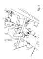
- a moistening station 3 and a winding station 4 are arranged one behind the other in the conveying direction 2 relative to a conveyor base 1 with conveying direction 2, for example a conventional conveyor belt.
- the moistening station 3 may be preceded by a stretching device 5.
- This has, each extending in the conveying direction 2, a feed conveyor 6 and a Weg211 technicalband 7, which are operable at different conveying speeds.
- the feed conveyor belt 6 is operated at a slower conveying speed than the discharge conveyor belt 7.
- the (not shown in Figure 2) dough piece is by means of a narrow Andschreibriemens 8 pressed onto the surface of the feed conveyor 6.
- An equivalent function with respect to the removal conveyor belt 7 fulfills the pressure roller 9, which is arranged downstream of the pressure belt 8 and extends with its longitudinal or rotational axis transversely to the conveying direction 2 over the surface of the Wegstocked professionbandes 7.
- the pressure roller 9 is replaced by a relation to the Andschreibriemen 8 wider Andschreibband 9a.
- the larger width of the pressure belt 9a and the pressure roller 9 compared to the respective Andschreibriemen 8 is expedient in that dough pieces are often wrapped in croissant shape, and serve as a starter exit piece for triangular cut dough pieces, in which the triangular base forms the leading end in the conveying direction 2 and runs transversely to the conveying direction 2.
- the drive and deflection shafts 10, around which the pressure belts 8 and the pressure belt 9a are guided, extend parallel to one another and transversely to the conveying direction 2.
- the moistening station 3 can be preceded by a cross-rolling or cross-roller device 11 in the conveying direction 2, in particular the moistening station 3 and the stretching device 5.
- the cross-roller device is only schematically indicated in the drawing and can be realized, for example, with two transverse rollers (not shown), which can be moved along a guide transversely to the conveying direction 2 from inside to outside and vice versa.
- the conveyor pad 1 may be identical to the Weg211 profession 7 according to Figure 2 or 3.
- a piece of dough to be wrapped is transported to the winding station 4 after leaving the moistening station to the winding station 4.
- the piece of dough initially comes in a Andschreib trimgang 12, which is formed between the support pad 1 and a plurality of parallel pressure plates 13.
- the pressure plates 13 exert thrust forces on the dough piece, so that it does not remain in the subsequent high-passage passage 14, but it is pushed in and pushed through.
- the pressure plates 13 provide a guide of the dough pieces parallel to the conveying direction 2.
- the pressure plates 13 are mounted on a common axis and / or shaft 13a. According to FIG. 1, the two pressure disks 13 have a gap 15 between them so that any filling material can pass undressed on a dough piece therebetween.
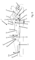
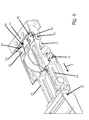
- the raising passage 14 is bounded by the conveying support 1 and by ladder-type and / or rung-like gripping profiles 16, which are fastened in each case to the end of a lever lug 17.
- the latter is articulated for pivoting movements 18 about a pivot axis 19, which passes through a winding machine frame part 20 transversely to the conveying direction 2.
- the upstroke passage 14 with overlap region 21 merges into a winding passage 22.
- This is bounded by the conveyor support 1 and by two wound battens 23, each associated with one end of the finished wound section (see FIG. 1). These run parallel to each other and to the conveying direction 2 and are provided in corresponding directions with long shots 24, in the example drawn long recesses for inserting, guiding, moving and fastening of pressure weights 25 (see Figure 1).
- This compensation movement game is optional and depends on the precision and backlash of the movable storage.
- an adjusting screw 28 is further arranged, which passes through the seen in the conveying direction 2 front end of a pivot lever 29 and is supported against the rear end of the Wickellatte 23.
- the Wickellatte 23 is hinged at its rear end via a transverse to the conveying direction 2 pivot lever axis 30 at the front end of the pivot lever 29. Due to this articulated connection, an angle between the respective winding batten 23 and the pivoting lever 29 can be set via the adjusting screw 28. As a result, it can be prevented that the winding mat 23 rests on the conveyor base and grinds thereon.
- the rear ends of the pivoting levers 29 remote from the winding slats 23 are hinged to the same pivot axis 19, with respect to which the lever tab 17 pivotal movements 18 can be issued.
- the floating bearing for the two Wickellatten 23 is further promoted by the articulation thereof to the front ends of the pivot lever 29 about the pivot lever axis 30.
- the winding slats 23 can thus perform with increasing winding diameter of the processed in the winding passage 22 dough pieces a complementary compensation pivotal movement 31 in a vertical or the support pad 1 vertical plane upwards.
- said complementary compensating pivotal movement 31 is reversed due to gravity again until the seen in the conveying direction 2 front ends 32 of the Wickellatten 23 on a respective stop shoulder 33 for Edition, which is attached via screw fasteners on a part of the general machine frame.
- the winding passage 22 is adjoined by an optional end-winding passage 34, which is delimited by the conveyor support 1 and by one or more winding plates 35.
- the latter are expediently arranged twice and each a Teigwickel-end section assigned.
- the seen in the conveying direction 2 rear, upwardly bent ends 36 are pivotally mounted about a plate pivot axis 37 in a vertical plane, the plate pivot axis 37, as well as the pivot lever axis 30 or the lever tab 17 and the pivot lever 29 common pivot axis 19, stationary in the machine frame are stored.
- Has the finished wound dough piece the Endwickel malgang 34 is lowered in a corresponding pivoting movement 35a in a vertical plane, the winding plate in the direction of the conveyor base 1.
- winding plates 35 can also be a known, flexible winding mat or -schleppe on the machine frame after the Wickellatten 23 be fixed so that in the conveying direction front mat end on the surface of the conveyor pad 1 along grinds, including a dough wrap can be rolled ready.
- the lever tabs 17 are each formed with a Schwenkhubbegrenzung, by means of which a sufficient height for the Hochstell suitgang 14 and a sufficient distance between the gripping profile 16 and the conveyor base 1 is ensured.
- the respective Schwenkhubbegrenzung comprises a seen in the conveying direction 2 rear end of the lever tab 17 formed approach 38, of which the support pad facing away from the top at least one stop element 39 protrudes. This is designed in the example shown as upwardly projecting pin with radially expanded stopper head 40 at the upper free end.
- the counter-stop element 41 is executed in the concrete example drawn as a stop-cross bar, which is associated with the two drawn stop elements 39 with its bottom 42.
- the conveying direction 2 extends perpendicularly into the plane of the drawing, so that the oblique entry area 43 of the raising passage 14, which runs obliquely with respect to the conveying support 1, becomes visible on the face side.
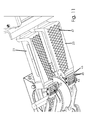
- the gripping profile 16 is designed with through-passage slots 44, each of which is delimited by two transverse webs 45.
- the latter are, with their longitudinal direction extending transversely to the conveying direction 2, on a support frame 46 approximately opposite to the conveying direction 2 and after the inclined entry portion 43 projecting welded or soldered to the conveyor base 1.
- the conveying direction 2 extends out of the plane of the drawing.
- the winding slats 23 are visible with their end faces and with respect to the conveyor base 1 beveled winding sub-walls 47.
- floating storage of Wickellatten 23 which allows, inter alia, a certain amount of movement in a plane approximately parallel to the conveyor base.
- the floating mounting tilting movements of the Wickellatten 23 about axes are conceivable, which are parallel to the conveying direction 2.
- plate-like stripping elements 49 are fastened to the underside of a machine frame part 48 and protrude to one of the pressure plates 13, for example. At the free end they are provided with U-shaped recesses 50, in which the pressure plates 13 are engaged with their respective peripheral edge, whereby Teigabrieb or the like can be stripped.
- the support frame 46 for the transverse webs 45 is subdivided into two sections over an obtuse angle 51, namely the oblique entrance area 43 already described and the narrow area 52 starting from the corner edge of the obtuse angle 51.
- the elevation passage 14 already described is made of these two areas 43, 52 assembled when the funding document is opposite.
- the transverse webs 45 delimit the passage slots 44, resulting in an approximately rib-like structure for the gripping profile 16.
- the width or width of the passage slots 44 is sized according to the thickness of the incoming dough pieces. The same applies to the thickness of the transverse webs 45. An emerging during the raising dough abrasion can easily pass through the slots 44, so that clogging of the gripping profile is avoided.
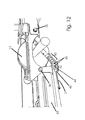
- a dough piece 53 which is pressed by the pressure disks 13 onto the conveying support 1 (not shown), is just about to abut with its front edge 54 against the transverse ribs or webs 45 with the passage slots 44 therebetween.
- the support frame 46 for the transverse webs 45 is still in its lowest position, which is secured by the stop members 39 and the counter-stop member 41. Further, the support frame 46 is at least partially below its narrow end portion 52 seen in the conveying direction rear end portion 55 of the Wickellatte 23.
- said distance 57 has been reduced such that the front end region of the support frame 46 has come into contact with the input bevel 58 in the rear end region 55 of the wound batten 23 by abutting contact 58.
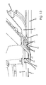
- This abuts with its front edge 54 against the transverse webs 45 of the gripping profile 16, wherein due to the force exerted by the conveyor pad thrust on the one gripping profile 16th is lifted together with lever tab 17, and on the other hand, the front-side edge 54 of the dough piece 53 folded up at least in the area of the corner of the corner 59 and is bent over.
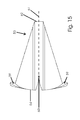
- the deformation of the dough piece 53 shown in FIG. 15 results, which has an equilateral-triangular basic shape.
- the frontal edge 54 forms the base.
- the height of the isosceles triangle which is perpendicular to the base or the frontal edge 54, is lengthened.
- the folding first the Stirnecken 59 and the subsequent raising of the entire frontal edge 54 is further facilitated by the central incision 60, the imaginary extension 61 corresponding to the triangle height by the truncated tip 62 of the isosceles triangle runs.
- a trapezoidal shape can be used to form the dough wrap for croissants.
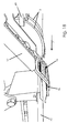
- the support frame 46 of the gripping profile 16 not only engages under the reel mat 23 but also partially overlaps one another (a part of the input bevel 56 of the reel mat 23 covers a part of the upper side of the narrow region 52 of FIG Gripping profile 16 - see overlap area 21 in Figure 5), there is also an overlap or simultaneity of the first phase of the folding up of the cam corners 59 and the second phase of flipping, wrapping and / or curling the entire end edge 54 of the dough piece 53. Approximately in In the second phase according to FIG.
- both the gripping profile 16 and the rear end region 55 of the winding mat 23 are maximally raised by the rolling front edge 54 of the dough piece 53, so that the high-passage passage as well as the entrance into the winding passage receive their maximum height and permeability to have.
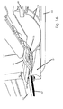
- the third phase is initiated, starting from the front-side dough piece edge 54 below the Wickellatten 23 of the complete dough wrap for croissants or the like is completed.
- the winding passage 22 or the Wickellatten 23 have largely maintained their height relative to the conveyor base, whereas due to leaving the bead with the chosen end-side dough piece edge 54 of the support frame 46 with the gripping profile 16 is lowered and thereby resting on the surface of the dough piece 53rd comes in the direction of conveying 2 rear area seen.
- the dough piece 53 has now also left the raising passage below the gripping profile 16 with its rear tip 62, so that the carrying frame 46 can continue to lower with the gripping profile 16 until the stop element 39 and counter-stop element 41 coincide. It comes at the high passage 14 now to the minimum height or width with respect to the conveyor base 1, and the gripping profile 16 is ready for raising the next piece of dough. In the winding passage, the previous piece of dough may still be in the processing, while in the sense of overlapping processing, the next piece of dough may already reach the high pass.
Landscapes
- Life Sciences & Earth Sciences (AREA)
- Engineering & Computer Science (AREA)
- Food Science & Technology (AREA)
- Manufacturing And Processing Devices For Dough (AREA)
- Bakery Products And Manufacturing Methods Therefor (AREA)
Priority Applications (1)
| Application Number | Priority Date | Filing Date | Title |
|---|---|---|---|
| EP07108377.8A EP1856979B1 (fr) | 2006-05-16 | 2007-05-16 | Système machinal d'enroulement de pâte |
Applications Claiming Priority (2)
| Application Number | Priority Date | Filing Date | Title |
|---|---|---|---|
| EP06400021 | 2006-05-16 | ||
| EP07108377.8A EP1856979B1 (fr) | 2006-05-16 | 2007-05-16 | Système machinal d'enroulement de pâte |
Publications (3)
| Publication Number | Publication Date |
|---|---|
| EP1856979A2 true EP1856979A2 (fr) | 2007-11-21 |
| EP1856979A3 EP1856979A3 (fr) | 2014-07-02 |
| EP1856979B1 EP1856979B1 (fr) | 2019-04-17 |
Family
ID=38441539
Family Applications (1)
| Application Number | Title | Priority Date | Filing Date |
|---|---|---|---|
| EP07108377.8A Ceased EP1856979B1 (fr) | 2006-05-16 | 2007-05-16 | Système machinal d'enroulement de pâte |
Country Status (1)
| Country | Link |
|---|---|
| EP (1) | EP1856979B1 (fr) |
Cited By (3)
| Publication number | Priority date | Publication date | Assignee | Title |
|---|---|---|---|---|
| EP2366290A1 (fr) | 2010-03-18 | 2011-09-21 | Fritsch GmbH | Dispositif d'enroulement de pâte développé pour la fabrication mécanique d'un produit de boulangerie roulé à partir d'un morceau de pâte de départ et procédé correspondant |
| CN104413097A (zh) * | 2013-09-08 | 2015-03-18 | 河南百安粮油有限公司 | 自动延伸装置 |
| EP4616715A4 (fr) * | 2022-11-08 | 2026-03-25 | Rheon Automatic Machinery Co | Dispositif de bouclage pour pâton |
Family Cites Families (3)
| Publication number | Priority date | Publication date | Assignee | Title |
|---|---|---|---|---|
| EP0202295A1 (fr) * | 1984-11-16 | 1986-11-26 | OSTALI S.r.L. | Machine a rouler la pate pour patisseries fourrees |
| NL8403780A (nl) * | 1984-12-12 | 1986-07-01 | Kamstra B V Geb | Inrichting voor het over het inwendige van deegklompen verdelen van luchtinsluitsels. |
| JP2750813B2 (ja) * | 1994-03-23 | 1998-05-13 | レオン自動機株式会社 | クロワッサン生地の巻き上げ装置 |
-
2007
- 2007-05-16 EP EP07108377.8A patent/EP1856979B1/fr not_active Ceased
Cited By (3)
| Publication number | Priority date | Publication date | Assignee | Title |
|---|---|---|---|---|
| EP2366290A1 (fr) | 2010-03-18 | 2011-09-21 | Fritsch GmbH | Dispositif d'enroulement de pâte développé pour la fabrication mécanique d'un produit de boulangerie roulé à partir d'un morceau de pâte de départ et procédé correspondant |
| CN104413097A (zh) * | 2013-09-08 | 2015-03-18 | 河南百安粮油有限公司 | 自动延伸装置 |
| EP4616715A4 (fr) * | 2022-11-08 | 2026-03-25 | Rheon Automatic Machinery Co | Dispositif de bouclage pour pâton |
Also Published As
| Publication number | Publication date |
|---|---|
| EP1856979B1 (fr) | 2019-04-17 |
| EP1856979A3 (fr) | 2014-07-02 |
Similar Documents
| Publication | Publication Date | Title |
|---|---|---|
| EP1997595B1 (fr) | Dispositif de coupe destiné à la coupe de matériaux en bandes, en particulier de bandes de textile ou de corde en acier | |
| DE69509956T2 (de) | Vorrichtung zum Aufwickeln von Teigstücken für Hörnchen | |
| DE3008842C2 (fr) | ||
| EP0740508A1 (fr) | Dispositif pour enrouler une bande de pate | |
| EP1285581B1 (fr) | Procédé et système pour former des produits pâteux roulés, notamment des croissants, à partir d'une pièce de pâte plane découpée | |
| EP1856979B1 (fr) | Système machinal d'enroulement de pâte | |
| DE69421056T2 (de) | Verbesserungen in einer Vorrichtung zur kontinuierlichen Herstellung von Hörnchen | |
| DE4215308C2 (de) | Rundballenpresse | |
| DE60305992T2 (de) | Vorrichtung zum Falten von Croissants | |
| DE3783649T2 (de) | Verfahren und apparat zum anfertigen von filtern aus einem dafuer geeigneten material. | |
| DE1948727C3 (de) | Maschine zum Aufwickeln von bahnförmigem Gut auf rohrförmige Wickelkerne | |
| DE1757404A1 (de) | Aufrollvorrichtung fuer Sodenstreifen | |
| EP0986306B1 (fr) | Procede et dispositif pour former des produits de boulangerie roules | |
| DE10118813C2 (de) | Vorrichtung zum Abstapeln von Faltschachtelschläuchen | |
| DE69612278T2 (de) | Ritzvorrichtung | |
| DE2603168C3 (de) | Vorrichtung zum etwa halbkreisförmigen Biegen von langgewirkten Backwarenrohlingen, insbesondere Kipferlrohlingen | |
| EP2138439A2 (fr) | Dispositif d'empilement de produits plats, notamment de produits d'impression | |
| DE1956268C3 (de) | Faltscheibe | |
| CH633429A5 (de) | Verfahren und apparat zum streckenweisen entfernen von aus ungefaehr schraubenlinienfoermig gewundenen kunststoffilamenten gebildeten kupplungsgliedern einer reissverschlusskette. | |
| DE29515556U1 (de) | Anordnung zur Übergabe von Teigstücken | |
| DE2308320B2 (de) | Vorrichtung zur Herstellung eines Körpers aus zwei Teilkörpern unter Bildung eines Hohlraumes | |
| DE3408149A1 (de) | Bindegarn-spannvorrichtung | |
| EP4361052B1 (fr) | Machine pour fermer les parois rabattables de colonnes montantes par actionnement du dispositif de verrouillage | |
| DE4012495C1 (fr) | ||
| DE4417336C2 (de) | Vorrichtung zum Ergreifen und Bearbeiten eines Teigstrangs |
Legal Events
| Date | Code | Title | Description |
|---|---|---|---|
| PUAI | Public reference made under article 153(3) epc to a published international application that has entered the european phase |
Free format text: ORIGINAL CODE: 0009012 |
|
| AK | Designated contracting states |
Kind code of ref document: A2 Designated state(s): AT BE BG CH CY CZ DE DK EE ES FI FR GB GR HU IE IS IT LI LT LU LV MC MT NL PL PT RO SE SI SK TR |
|
| AX | Request for extension of the european patent |
Extension state: AL BA HR MK YU |
|
| RIC1 | Information provided on ipc code assigned before grant |
Ipc: A21C 3/06 20060101AFI20140130BHEP |
|
| PUAL | Search report despatched |
Free format text: ORIGINAL CODE: 0009013 |
|
| AK | Designated contracting states |
Kind code of ref document: A3 Designated state(s): AT BE BG CH CY CZ DE DK EE ES FI FR GB GR HU IE IS IT LI LT LU LV MC MT NL PL PT RO SE SI SK TR |
|
| AX | Request for extension of the european patent |
Extension state: AL BA HR MK RS |
|
| RIC1 | Information provided on ipc code assigned before grant |
Ipc: A21C 3/06 20060101AFI20140523BHEP |
|
| 17P | Request for examination filed |
Effective date: 20141209 |
|
| RBV | Designated contracting states (corrected) |
Designated state(s): AT BE BG CH CY CZ DE DK EE ES FI FR GB GR HU IE IS IT LI LT LU LV MC MT NL PL PT RO SE SI SK TR |
|
| AKX | Designation fees paid |
Designated state(s): CH DE ES IT LI NL |
|
| AXX | Extension fees paid |
Extension state: HR Extension state: AL Extension state: MK Extension state: RS Extension state: BA |
|
| RBV | Designated contracting states (corrected) |
Designated state(s): CH DE ES IT LI NL |
|
| GRAP | Despatch of communication of intention to grant a patent |
Free format text: ORIGINAL CODE: EPIDOSNIGR1 |
|
| INTG | Intention to grant announced |
Effective date: 20181120 |
|
| GRAS | Grant fee paid |
Free format text: ORIGINAL CODE: EPIDOSNIGR3 |
|
| GRAA | (expected) grant |
Free format text: ORIGINAL CODE: 0009210 |
|
| REG | Reference to a national code |
Ref country code: DE Ref legal event code: R081 Ref document number: 502007016642 Country of ref document: DE Owner name: FRITSCH BAKERY TECHNOLOGIES GMBH & CO. KG, DE Free format text: FORMER OWNER: FRITSCH GMBH, 97348 MARKT EINERSHEIM, DE |
|
| AK | Designated contracting states |
Kind code of ref document: B1 Designated state(s): CH DE ES IT LI NL |
|
| REG | Reference to a national code |
Ref country code: CH Ref legal event code: EP |
|
| REG | Reference to a national code |
Ref country code: DE Ref legal event code: R096 Ref document number: 502007016642 Country of ref document: DE |
|
| REG | Reference to a national code |
Ref country code: CH Ref legal event code: NV Representative=s name: SCHNEIDER FELDMANN AG PATENT- UND MARKENANWAEL, CH |
|
| REG | Reference to a national code |
Ref country code: NL Ref legal event code: FP |
|
| REG | Reference to a national code |
Ref country code: DE Ref legal event code: R082 Ref document number: 502007016642 Country of ref document: DE Representative=s name: GRUENECKER PATENT- UND RECHTSANWAELTE PARTG MB, DE Ref country code: DE Ref legal event code: R081 Ref document number: 502007016642 Country of ref document: DE Owner name: FRITSCH BAKERY TECHNOLOGIES GMBH & CO. KG, DE Free format text: FORMER OWNER: FRITSCH GMBH, 97348 MARKT EINERSHEIM, DE |
|
| PG25 | Lapsed in a contracting state [announced via postgrant information from national office to epo] |
Ref country code: ES Free format text: LAPSE BECAUSE OF FAILURE TO SUBMIT A TRANSLATION OF THE DESCRIPTION OR TO PAY THE FEE WITHIN THE PRESCRIBED TIME-LIMIT Effective date: 20190417 |
|
| REG | Reference to a national code |
Ref country code: DE Ref legal event code: R082 Ref document number: 502007016642 Country of ref document: DE Representative=s name: GRUENECKER PATENT- UND RECHTSANWAELTE PARTG MB, DE |
|
| REG | Reference to a national code |
Ref country code: CH Ref legal event code: PUE Owner name: FRITSCH BAKERY TECHNOLOGIES GMBH AND CO. KG, DE Free format text: FORMER OWNER: FRITSCH GMBH, DE |
|
| REG | Reference to a national code |
Ref country code: NL Ref legal event code: PD Owner name: FRITSCH BAKERY TECHNOLOGIES GMBH & CO. KG; DE Free format text: DETAILS ASSIGNMENT: CHANGE OF OWNER(S), ASSIGNMENT; FORMER OWNER NAME: FRITSCH GMBH Effective date: 20191230 |
|
| REG | Reference to a national code |
Ref country code: DE Ref legal event code: R097 Ref document number: 502007016642 Country of ref document: DE |
|
| REG | Reference to a national code |
Ref country code: DE Ref legal event code: R082 Ref document number: 502007016642 Country of ref document: DE Representative=s name: GRUENECKER PATENT- UND RECHTSANWAELTE PARTG MB, DE |
|
| PLBE | No opposition filed within time limit |
Free format text: ORIGINAL CODE: 0009261 |
|
| STAA | Information on the status of an ep patent application or granted ep patent |
Free format text: STATUS: NO OPPOSITION FILED WITHIN TIME LIMIT |
|
| 26N | No opposition filed |
Effective date: 20200120 |
|
| REG | Reference to a national code |
Ref country code: CH Ref legal event code: NV Representative=s name: SCHNEIDER FELDMANN AG PATENT- UND MARKENANWAEL, CH |
|
| PGFP | Annual fee paid to national office [announced via postgrant information from national office to epo] |
Ref country code: CH Payment date: 20200522 Year of fee payment: 14 |
|
| REG | Reference to a national code |
Ref country code: CH Ref legal event code: PFA Owner name: FRITSCH BAKERY TECHNOLOGIES GMBH AND CO. KG, DE Free format text: FORMER OWNER: FRITSCH BAKERY TECHNOLOGIES GMBH AND CO. KG, DE |
|
| REG | Reference to a national code |
Ref country code: CH Ref legal event code: PL |
|
| PG25 | Lapsed in a contracting state [announced via postgrant information from national office to epo] |
Ref country code: CH Free format text: LAPSE BECAUSE OF NON-PAYMENT OF DUE FEES Effective date: 20210531 Ref country code: LI Free format text: LAPSE BECAUSE OF NON-PAYMENT OF DUE FEES Effective date: 20210531 |
|
| P01 | Opt-out of the competence of the unified patent court (upc) registered |
Effective date: 20230329 |
|
| PGFP | Annual fee paid to national office [announced via postgrant information from national office to epo] |
Ref country code: NL Payment date: 20230519 Year of fee payment: 17 Ref country code: IT Payment date: 20230531 Year of fee payment: 17 Ref country code: DE Payment date: 20230519 Year of fee payment: 17 |
|
| REG | Reference to a national code |
Ref country code: DE Ref legal event code: R119 Ref document number: 502007016642 Country of ref document: DE |
|
| REG | Reference to a national code |
Ref country code: NL Ref legal event code: MM Effective date: 20240601 |
|
| PG25 | Lapsed in a contracting state [announced via postgrant information from national office to epo] |
Ref country code: NL Free format text: LAPSE BECAUSE OF NON-PAYMENT OF DUE FEES Effective date: 20240601 |
|
| PG25 | Lapsed in a contracting state [announced via postgrant information from national office to epo] |
Ref country code: DE Free format text: LAPSE BECAUSE OF NON-PAYMENT OF DUE FEES Effective date: 20241203 |
|
| PG25 | Lapsed in a contracting state [announced via postgrant information from national office to epo] |
Ref country code: IT Free format text: LAPSE BECAUSE OF NON-PAYMENT OF DUE FEES Effective date: 20240516 |