EP1857616A2 - Fermeture à fixer dans des ouvertures menagées dans une paroi mince - Google Patents
Fermeture à fixer dans des ouvertures menagées dans une paroi mince Download PDFInfo
- Publication number
- EP1857616A2 EP1857616A2 EP20070011329 EP07011329A EP1857616A2 EP 1857616 A2 EP1857616 A2 EP 1857616A2 EP 20070011329 EP20070011329 EP 20070011329 EP 07011329 A EP07011329 A EP 07011329A EP 1857616 A2 EP1857616 A2 EP 1857616A2
- Authority
- EP
- European Patent Office
- Prior art keywords
- closure
- closure according
- holding elements
- body part
- lever
- Prior art date
- Legal status (The legal status is an assumption and is not a legal conclusion. Google has not performed a legal analysis and makes no representation as to the accuracy of the status listed.)
- Withdrawn
Links
Images












Classifications
-
- E—FIXED CONSTRUCTIONS
- E05—LOCKS; KEYS; WINDOW OR DOOR FITTINGS; SAFES
- E05C—BOLTS OR FASTENING DEVICES FOR WINGS, SPECIALLY FOR DOORS OR WINDOWS
- E05C3/00—Fastening devices with bolts moving pivotally or rotatively
- E05C3/02—Fastening devices with bolts moving pivotally or rotatively without latching action
- E05C3/04—Fastening devices with bolts moving pivotally or rotatively without latching action with operating handle or equivalent member rigid with the bolt
- E05C3/041—Fastening devices with bolts moving pivotally or rotatively without latching action with operating handle or equivalent member rigid with the bolt rotating about an axis perpendicular to the surface on which the fastener is mounted
- E05C3/042—Fastening devices with bolts moving pivotally or rotatively without latching action with operating handle or equivalent member rigid with the bolt rotating about an axis perpendicular to the surface on which the fastener is mounted the handle being at one side, the bolt at the other side or inside the wing
-
- E—FIXED CONSTRUCTIONS
- E05—LOCKS; KEYS; WINDOW OR DOOR FITTINGS; SAFES
- E05B—LOCKS; ACCESSORIES THEREFOR; HANDCUFFS
- E05B1/00—Knobs or handles for wings; Knobs, handles, or press buttons for locks or latches on wings
-
- E—FIXED CONSTRUCTIONS
- E05—LOCKS; KEYS; WINDOW OR DOOR FITTINGS; SAFES
- E05B—LOCKS; ACCESSORIES THEREFOR; HANDCUFFS
- E05B1/00—Knobs or handles for wings; Knobs, handles, or press buttons for locks or latches on wings
- E05B1/0092—Moving otherwise than only rectilinearly or only rotatively
-
- E—FIXED CONSTRUCTIONS
- E05—LOCKS; KEYS; WINDOW OR DOOR FITTINGS; SAFES
- E05B—LOCKS; ACCESSORIES THEREFOR; HANDCUFFS
- E05B9/00—Lock casings or latch-mechanism casings ; Fastening locks or fasteners or parts thereof to the wing
- E05B9/08—Fastening locks or fasteners or parts thereof, e.g. the casings of latch-bolt locks or cylinder locks to the wing
-
- E—FIXED CONSTRUCTIONS
- E05—LOCKS; KEYS; WINDOW OR DOOR FITTINGS; SAFES
- E05C—BOLTS OR FASTENING DEVICES FOR WINGS, SPECIALLY FOR DOORS OR WINDOWS
- E05C9/00—Arrangements of simultaneously actuated bolts or other securing devices at well-separated positions on the same wing
- E05C9/04—Arrangements of simultaneously actuated bolts or other securing devices at well-separated positions on the same wing with two sliding bars moved in opposite directions when fastening or unfastening
- E05C9/041—Arrangements of simultaneously actuated bolts or other securing devices at well-separated positions on the same wing with two sliding bars moved in opposite directions when fastening or unfastening with rack and pinion mechanism
-
- E—FIXED CONSTRUCTIONS
- E05—LOCKS; KEYS; WINDOW OR DOOR FITTINGS; SAFES
- E05B—LOCKS; ACCESSORIES THEREFOR; HANDCUFFS
- E05B17/00—Accessories in connection with locks
- E05B17/0025—Devices for forcing the wing firmly against its seat or to initiate the opening of the wing
-
- E—FIXED CONSTRUCTIONS
- E05—LOCKS; KEYS; WINDOW OR DOOR FITTINGS; SAFES
- E05D—HINGES OR SUSPENSION DEVICES FOR DOORS, WINDOWS OR WINGS
- E05D5/00—Construction of single parts, e.g. the parts for attachment
- E05D5/02—Parts for attachment, e.g. flaps
- E05D5/0215—Parts for attachment, e.g. flaps for attachment to profile members or the like
- E05D5/0223—Parts for attachment, e.g. flaps for attachment to profile members or the like with parts, e.g. screws, extending through the profile wall or engaging profile grooves
- E05D5/023—Parts for attachment, e.g. flaps for attachment to profile members or the like with parts, e.g. screws, extending through the profile wall or engaging profile grooves with parts extending through the profile wall
-
- E—FIXED CONSTRUCTIONS
- E05—LOCKS; KEYS; WINDOW OR DOOR FITTINGS; SAFES
- E05Y—INDEXING SCHEME ASSOCIATED WITH SUBCLASSES E05D AND E05F, RELATING TO CONSTRUCTION ELEMENTS, ELECTRIC CONTROL, POWER SUPPLY, POWER SIGNAL OR TRANSMISSION, USER INTERFACES, MOUNTING OR COUPLING, DETAILS, ACCESSORIES, AUXILIARY OPERATIONS NOT OTHERWISE PROVIDED FOR, APPLICATION THEREOF
- E05Y2600/00—Mounting or coupling arrangements for elements provided for in this subclass
- E05Y2600/60—Mounting or coupling members; Accessories therefor
- E05Y2600/63—Retainers
-
- Y—GENERAL TAGGING OF NEW TECHNOLOGICAL DEVELOPMENTS; GENERAL TAGGING OF CROSS-SECTIONAL TECHNOLOGIES SPANNING OVER SEVERAL SECTIONS OF THE IPC; TECHNICAL SUBJECTS COVERED BY FORMER USPC CROSS-REFERENCE ART COLLECTIONS [XRACs] AND DIGESTS
- Y10—TECHNICAL SUBJECTS COVERED BY FORMER USPC
- Y10T—TECHNICAL SUBJECTS COVERED BY FORMER US CLASSIFICATION
- Y10T70/00—Locks
- Y10T70/50—Special application
- Y10T70/5611—For control and machine elements
- Y10T70/5757—Handle, handwheel or knob
- Y10T70/5761—Retractable or flush handle
-
- Y—GENERAL TAGGING OF NEW TECHNOLOGICAL DEVELOPMENTS; GENERAL TAGGING OF CROSS-SECTIONAL TECHNOLOGIES SPANNING OVER SEVERAL SECTIONS OF THE IPC; TECHNICAL SUBJECTS COVERED BY FORMER USPC CROSS-REFERENCE ART COLLECTIONS [XRACs] AND DIGESTS
- Y10—TECHNICAL SUBJECTS COVERED BY FORMER USPC
- Y10T—TECHNICAL SUBJECTS COVERED BY FORMER US CLASSIFICATION
- Y10T70/00—Locks
- Y10T70/70—Operating mechanism
- Y10T70/7441—Key
- Y10T70/7486—Single key
- Y10T70/7508—Tumbler type
- Y10T70/7559—Cylinder type
- Y10T70/7655—Cylinder attaching or mounting means
-
- Y—GENERAL TAGGING OF NEW TECHNOLOGICAL DEVELOPMENTS; GENERAL TAGGING OF CROSS-SECTIONAL TECHNOLOGIES SPANNING OVER SEVERAL SECTIONS OF THE IPC; TECHNICAL SUBJECTS COVERED BY FORMER USPC CROSS-REFERENCE ART COLLECTIONS [XRACs] AND DIGESTS
- Y10—TECHNICAL SUBJECTS COVERED BY FORMER USPC
- Y10T—TECHNICAL SUBJECTS COVERED BY FORMER US CLASSIFICATION
- Y10T70/00—Locks
- Y10T70/80—Parts, attachments, accessories and adjuncts
- Y10T70/8432—For key-operated mechanism
- Y10T70/8459—Housings
- Y10T70/8486—Cylindrical
Definitions
- the invention relates to a closure, such as socket wrench closure, swivel lever lock, folding lever lock, cam lock for mounting in openings in a thin wall, comprising a on the one, outer side of the thin wall to be arranged, the outer edge of the opening overlapping head portion, of which a breakthrough in protruding body part protrudes from projecting in the direction of its outer surface retaining elements whose free end an inclined surface for play-free support of the body part on the edge of the opening of the other, inner side of the thin wall, are provided, said body part and retaining element two separate parts are.
- a closure such as socket wrench closure, swivel lever lock, folding lever lock, cam lock for mounting in openings in a thin wall, comprising a on the one, outer side of the thin wall to be arranged, the outer edge of the opening overlapping head portion, of which a breakthrough in protruding body part protrudes from projecting in the direction of its outer surface retaining elements whose free end an inclined surface for play-free support of the
- Such a closure is from the US-A-5,251,467 already known.
- the resilient retaining elements of the US-A-5,251,467 Known closure are formed by the ends of a bow-shaped spring, see Figs. 6 and 8 and Fig. 11. These ends are bent at an angle or twisted by 90 degrees, whereby in the mounting position an inlet chamfer and a vertical support bevel arises.
- a similar bow-shaped spring with twisted strap ends for attaching a rotary latch closure shows the BE 883 121 A1 (LOWE & FLETCHER BELGE SA et al. )
- the object of the invention is to provide a development of the known arrangement, where these disadvantages do not occur and allow easy installation without loss of mounting means, such as nuts or screws are not removable without special tools are shakeproof and allow high strength.
- the object is achieved, in particular the achievement of high strength and vibration resistance in that the holding elements are spaced apart from the thin wall about a parallel to the plane of the thin wall or about an axis perpendicular to the plane of the thin wall rotatably arranged lever.
- levers are held by a self-locking between them or a the axisdorfdem bearing part latching hook device against compression spring force (claim 2).
- the simplest is an embodiment in which the body part and head part are injection molded in one piece, for example made of plastic (claim 20). But it is also possible to form the body part and the head part as two parts which are bolted together, welded, glued or clipped. (Claim 21).
- supporting elements supported or carried in the body part for supporting the holding elements after the closure has been mounted in the thin wall are provided in the body part. (Claim 22).
- two diametrically opposed holding elements are provided, which are supported by spring devices such as coil spring and / or wedge devices such as tapered screw (claim 23). Since the spring devices can be provided with freely selectable spring force, the locking force can be adapted to the respective task and is not dependent on the plastic material.
- the locking force is highly dependent on the shape of the fitting and the material property of the plastic used.
- a further embodiment is characterized in that the holding elements are made of rigid material, such as metal, which are held against compression spring force by a pinning device arranged between them. (Claim 4).
- the pinning device can also consist of screws screwed in the head part, wherein according to yet another embodiment there is the possibility that the screws fix the body part on the head part. (Claims 5 and 6).
- the support member may have a part partition or undercut or breakthrough edge on which lever with a shoulder or hook axially support. (Claim 7).
- the body part may have a slot for receiving a grounding spring.
- closure is a pivot or folding lever lock for attachment in an elongated or in two shorter rectangular openings, wherein the one opening the lever storage, z. B. the drive shaft and the other breakthrough receives a lever lock, is characterized in that at least one of the apertures also serves to receive at least one holding element according to one of the preceding embodiments. (Claim 8).
- the pivot lever lock may comprise a trough for locking the actuating lever, wherein according to the invention the trough form the head part of one or two holding elements in the region of the lever support, such as the drive shaft. (Claim 9).
- the swivel lever lock may have a recess for the lockable recording of the operating lever, and be characterized in that the trough on the one hand forms the Schugrifffcheche for the thumb of a Bet2011istshebelarrettechnik, on the other hand, the head part of a holding element in the Bet2011 whyshebelarretmaschine. (Claim 10).
- the holding elements are formed by pivoted levers whose direction of movement are perpendicular to the longitudinal extension of the trough. (Claim 11).
- the holding elements can be replaced in a simplified manner by a leaf spring (claim 12). It is possible that the leaf spring is held in a slot formed by the body part (claim 13). Alternatively, however, the leaf spring can also be supported by a screw held in the body part. In such embodiments, it is beneficial for grounding, when the leaf spring at her free end has a cutting edge for laying on the thin metal wall in this case between a ground connection.
- the holding element is formed by a stamped part.
- the holding element is formed by a round bolt.
- the head part in the region of the retaining element, has a recess for receiving edge bulges.
- the closure has a folding lever pivotably mounted in the body part about an axis, and at least two pairs of opposing holding elements in cavities formed by the body part are held pivotably in a direction parallel or perpendicular to the axis.
- the closure on a mounted in the head and torso part drive, which carries a Vorreiberzunge.
- two or more holding elements can each be arranged side by side.
- Fig. 1 is a longitudinal sectional view of a pivot lever closure 10 which is in two rectangular openings 12, 14 of a thin wall 16, here a sheet metal door leaf, arranged, see also Fig. 27 leaves the center bar 17th away, results in a long rectangular opening, which would also be suitable.
- the SchwenkhebelVerInstitut includes in the region of each opening 12 and 14 on the one, outer side 18 of the thin wall 16 to be arranged, the outer edge 20 of the opening 12 and 14 overlapping head part, here in the form of the pivot lever 22 receiving trough 24, from which head part or trough 24, the hull part 26 protrudes through the opening 12 or 14 in the mounted position. From this body part 26 jump, as Fig. 3, in the direction of the outer surface 34 resilient tongues or holding elements 36 before, the free end of an inclined surface 38 for backlash-free support of the body part 26, 28 on the edge or the edge 40 of the opening 12 and 14 of the other, inner side 42 of the thin wall 16 has.
- the locking elements are hooks hooking each other, wherein the material of these hooks expediently consists of polyamide, that is flexible enough to sufficiently dodge the linear insertion of the holding elements 36 in the body part 26, 28 and past each other reach and springing back according to Fig. 2 hooked above and below, so that they remain in the position shown in FIG.
- This fuse can be designed by appropriately strong spring means 44 so that under normal circumstances and operating conditions, the retaining elements or Klips institute 36 does not retract against the force of the spring 44.
- the closure comprises, as shown here, a projection tongue 52 which lies behind a door frame edge 50
- the two diametrically opposed holding elements 36, 136 are loaded to different degrees.
- the pressure exerted on the side of the tongue 52 in its rear grip position is for the most part taken up by the holding element 36 opposite edge 20 of the tiller, while the holding member 36 is little loaded, which is exactly the opposite on the opposite side, as this holding member 136 is the strongest loaded.
- the two levers 236 are pressed at their inner end in each case by a common strong compression spring 244 to the outside.
- the tongue can be provided with a rotatable cross-abutment, which is indicated at 64. Also connected to the trough bar lock body with pinion and rods can be mounted and clipped, especially if the central web 17 is omitted between the two openings 12, 14 in the thin wall 16 and so an elongated opening is formed, the openings 12, 14, see Fig. 27.
- the upper body portion 26, which projects from the trough 14, serves as a bearing for a drive shaft 66, at whose lying outside the door leaf end of the hand lever 22 is pivotally pivoted about an axis perpendicular to the door leaf axis 68 while the inner end of the shaft 66 terminates with a square on which a square opening having tongue 52 is fitted and held by a fastening screw 72.
- a receiving portion 30 for an outgoing from the hand lever 22 cylinder lock interlocking part, with excentered tongue or thumb 70 is provided, which can be locked behind a return surface 74 by actuation of a cylinder key 76 in the retracted position.
- a spring rear handle 174 is provided, wherein the rotating tongue 170 could be mounted in a torsionally rigid manner on the cylinder roller by means of clip devices.
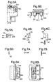
- a construction may also be selected, as has already been described in connection with the pivot lever closure, or as selected according to an embodiment according to FIGS. 6A to 6C.
- hooking hook here serves a pin according to FIG. 6D as a lock.
- Two metal components according to FIGS. 6A to 6C are inserted into a rectangular guide channel according to FIG. 8B and held in the inserted position by a pin screwed from the outside according to FIG. 6D, in such a way that they move a short distance apart, however can not fall out.
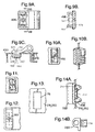
- the rectangular opening required for this purpose in the door frame 250 or in the door leaf 216 is shown, for example, in FIG. 13 and provided with the reference number 78.
- FIGs. 9A, 9B and 9C an embodiment of e.g. B. is shown for a hinge in which a hinge part is welded to the door leaf 416, while the other hinge part is held on the door frame 450 with a further embodiment of the invention Klipsbefest Trent.
- This consists of the door leaf plane at a distance about an axis perpendicular to the door leaf plane, formed by a bearing support 445, rotatably arranged lever means 436 which are urged by spring means 444 to the outside and then engage edge portions of a arranged in the door frame 450 rectangular opening.
- the movement path of the holding elements is limited here by outgoing from the head part 424 stop supports 447th
- FIGS. 10A and 10B show an embodiment in which the two holding elements, which can be pressed apart by spring devices, are held to one another by hooks, between which an inclined wedge 192 is arranged. A similar construction is shown in FIG. 11.
- a round pin 292 is provided which holds two mutually displaceable, made of hard material such as metal parts in position.
- a rectangular opening 78 is shown, as it is suitable for the embodiment described here, a lock. So z.
- a hinge member as shown in FIGS. 14A and 14B in side view and front view, are clipped into this rectangular opening 78.
- the structure is similar to that of FIG. 5B, but this is an (upper) hinge part 282.
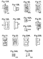
- Figs. 15A, 15B, 16 and 17 are illustrations of a mounting in which, as shown in Fig. 15A, upper part, a pivot lever, as shown in Fig. 15A, lower part, a hinge part can be fixed in a rectangular opening of a thin wall.
- a single spring is provided which presses both holding elements 536 from the pushed-back clip position shown in FIG. 17 in the clipped position shown in FIG. 16, when the component or the fitting is pressed into the mounting hole.
- FIGS. 19A and 19B show the associated item as hinge lugs. It is important that here the hook of the holding element 536 is supported on a wall opening 96.
- a solution is found here, with a spring and end opening in which hold the clip members 636 with hooks in the assembled state.
- FIGS. 20, 21, 22, 23A, 23B, 24A, 24B which is similar to the embodiment according to FIGS. 15 to 19, instead of the end-face opening, a lateral one in the holding or Guided channel provided. In both cases the advantage is that you can do it with just one spring.
- 26A and 26B show an embodiment in two different views, in which the conical screw 98, two holding elements 736 are pressed apart, resulting in a particularly large holding force, the screw head is located inside and a Blindbefest Trent is not possible. But you could also tighten with a screw from the outside a conical nut, which would have the same effect, and also would allow a blind assembly.
- Fig. 25 shows a pivot lever with a arranged at the bottom end, known per se hook attachment, however, at the upper end of the invention holding elements 836 are provided. Since only small forces are effective at the lower end according to FIG. 25, a hook fastening by means of a hook 100 is sufficient, while in the tongue region 52, where the closing forces and the rotation of the hand lever cause greater forces to occur, the device 836 according to the invention is provided it is one of the above embodiments, be it specifically the embodiment 736 by means of a conical screw.
- a hook 100 At the other end of the key plate or head part 24 is in Fig. 25 is a hook 100.
- a socket wrench In the embodiment of FIG. 29 is a socket wrench, in the embodiment of FIG. 30 to a lever lock.
- FIG. 31A shows in a sectional view from above a fitting part, here a hinge part 382, on whose head part forming tabs 388 the body part 326 is fastened by means of cap screws 27. These screws 27 simultaneously limit the stroke of the fastening elements 1136, see the slot 29, in which the screw cross section 27 can migrate.
- FIGS. 31B or 31C an axial sectional view in a bottom view, upon insertion, the members 1136 in the channel move inwardly against the force of the spring 344 as far as the elongated hole extension 29 permits, and then back in Jump lock position, which can be seen in Fig. 31B.
- This separation of the head and torso parts of the fastening system is z. B. advantageous if grooves 31 are to be provided for Abdichtringe 33. This can lead to tools for the injection molding process, which are difficult to handle when a one-piece production is desired.
- the illustrative hinge portion 382 is shown in three different views in FIGS. 32A, 32B, and 32C.
- the groove 35 can be seen, in which the free legs of the U-part 326 are used, as well as the threaded holes 37, in which the screws 27 can be screwed.
- the holding element used here is shown in FIGS. 33A to 33C as a single part, including the receiving blind hole 39 for receiving a compression spring 44th
- FIGS. 34A and 34B the guide member for the holding members 1136 is shown in an end view and a side view.
- the recess for the pivot lever closure is held by means arranged at both ends Klips instituten, which is formed by a spring, said spring 1236 in 36A and B in a side view and a top view again shown as a single part and can be fixed with its screw 41 in the trough.
- the spring 1236 is adapted to the outer contours of the holding elements described with reference to the present figures and designed with such a spring force as they are also supplied by the elements.
- the free ends of the spring 1236 have play inwards, so that when inserting the ends of the spring can recede.
- the attachment with a screw 41, which is inserted through a hole 443 in the spring 1236, is sufficient because the free ends 45 of the spring are guided on a wall 47 formed by the trough.
- the material of the trough of electrically conductive material, such as metal the spring 1236 can simultaneously serve for earthing purposes, in which the end 45 of the spring with momentum lays on the edge of the opening and breaks through there existing oxide and paint residues, if after pushing the spring relaxed. This creates an electrical route from the trough to the door leaf on the spring 1236 and the mounting screw 41st
- the grounding contact can be improved if the cutting edge 49 is sharp-edged.
- FIGS. 37A, 37B and 38 also show an embodiment which operates with a spring, which spring 1336 is not screwed to the body part 526 of a fitting part which is not of interest here, as in FIG. 35D, but rather is inserted in one Side slot 51 which is open to the outside, so as shown in FIG. 38 in the direction of the breakthrough edge of the thin wall 16, so that the spring 1336 can not slip out in this direction when the fitting is mounted, as shown in Fig. 37B ,
- a grounding spring for hinges or closures can be arranged in the region of the guide channel for the clip elements, one side each for metallic connection of the metal door or the door leaf or frame on the one hand and the hinge or the closure cap on the other hand is taken care of.
- the U-shaped spring 57 shown in side view and end view in FIGS. 40A and 40B is provided with a toothing 53 directed inwards, to the body of the body part of the fastening element, and also with a toothing pointing outwards at 55, to contact the aperture of the thin wall, as shown in Fig. 40C.
- a somewhat different construction for a grounding spring 157 is shown in Figs. 41A, B and 42A, B and C.
- An outwardly facing toothing 155 contacts the sheet similar to the embodiment just described, while the sharp edge tooth 153 contacts the body of the Guide channel for the holding elements is applied and produces this electrical contact.
- the grounding spring 157 is, as shown in Fig. 41A can be clearly seen, arranged centrally above the tunnel, which is provided for the clips.
- the spring ends 59 are bent over so that they remain in the grounding position.
- the upper tips 153 are each flattened and dig into the body portion of the hinge body (left portion of Fig. 41A) or the trough of a pivot lever lock (Fig. 41A right portion).
- this is only necessary for painted parts.
- the scalloped saw teeth 155 scrape the paint away in the opening, so that a good ground connection is also made to the opening or to the door leaf.
- a pivot lever lock is fastened to the body part by means of a spring arrangement by means of two screws.
- the arrangement according to the invention is also suitable for a bar closure, in particular for its lock case, see FIGS. 44A, 44B and 44C and 44D.
- Shown in different views here is a socket wrench closure, which is held in the rectangular opening of a door leaf by means of bolted 141 spring 1536. At the same time this spring serves as storage for the pinion.
- FIGS. 45A, 45B the spring 1536 is again shown separately, and the hole 143 for the fastening screw 141 and the hole 63 for the pinion can be seen clearly.
- fastening is provided by means of fastening elements arranged in a channel, see reference numeral 1636.
- the fastening here takes place with retaining elements 1636 arranged on the end faces, which, since they are somewhat shorter than in other embodiments, in addition, are guided by a groove, which can be seen at 65, see FIGS. 51A, 51B, 51C, while the bearing of the pinion, shown in FIGS. 52A, 52B, takes place in a body part 1632, which in FIG. 47C is recognize, in Fig.
- a lid 67 can be seen, which represents an additional storage for the pinion.
- This cover can be supported either on a recess 69 in the body part of the fitting, see Fig. 48A, 48B, or at the edges of the locking rods 71, as in Figs. 46B, 47B recognizable.
- 54A, 54B, 54C, 54D show a similar construction as described above, but here the clip attachment for the cap is arranged at the front corners and these engage in apertures formed by the lid shown in FIGS. 55A, 55B, 55C and 55D, ie the hooks 73 engage in the openings 75 shown in FIG. 55C, so that the holder according to FIG. 55A results.
- FIGS. 56A, 56B Shown in FIGS. 56A, 56B is a toggle fastener with locking bar 71, which operates without a cap, but instead has a one-piece housing, with lateral guide webs 79 for the rods 71 carrying clip means 77, thereby holding the rods.
- the attachment of the housing by means of a hook 81 on one side (in Fig. 56A right) and on the other side by means of Holding elements device 1836 according to the invention.
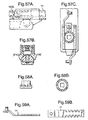
- FIGS. 57A to 57C show a similar construction, but here with a pivoting lever.
- the rods 71 can be inserted from above against the action of the Klips worn and engage with the detail drawn out in Figs. 58A and 58B pinion engaged.
- the rods are toothed on both sides as shown in FIG. 59A, 59B.
- 61A, 61B has at its one end a hook 181, and at its other end a clip fastening according to the invention, 2036, see FIG. 66.
- the cap of the lock case can be clipped on the front side, see FIGS. 61B, reference numeral 81.
- the rods are bent on both sides in cross section, resulting in a particularly narrow construction.
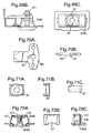
- FIGS. 69A, 69B is a housing clipped in accordance with the invention, with fastening elements 2136, which housing has an attached adapter 87, shown in FIGS. 71A, 71B, 71C, by means of which adapter 87 a wing tongue 89 , shown in FIGS. 70A, 70B, can be mounted.
- Round rods 271 can be attached to the wing tongue, as shown in FIGS. 69A, 69B.
- the adapter forms stop surfaces 91, see Fig. 69C, to which the nose 93 abuts the Drehwegbegrenzung the wing tongue 89.
- FIGS. 72A, 72B, 72C and 72D illustrate an embodiment in which a holding device 2436 according to the invention in the form of a spring clip arrangement for fastening a fitting, such as a hinge or closure, is shown in a thin wall.
- a holding device 2436 for fastening a fitting, such as a hinge or closure, is shown in a thin wall.
- An integrated leaf spring 102 is held like the separate U-shaped part 101 with a countersunk screw 103 which is screwed into the head part 2424. Also, the leaf spring 102 is inexpensive to produce.
- Figures 73A, 73B and 73C show, in three different views, a leaf spring snap fastener with channel assembly at the hinge or closure rear.
- the channel 2536 described above is opened upwards, so that a slot 104 is formed.
- a specially shaped leaf spring 105 according to FIG. 73A can be inserted laterally.
- the raised central region 106 can dodge down and finally engages in the slot 104 and then leaves a longitudinal displacement of the spring 105 is no longer.
- the two protruding ends of the leaf spring, reference numeral 107 now act as linearly displaceable springs for the clip elements and hold the fitting part, for example a hinge device in the rectangular mounting hole 109 fixed.
- This embodiment is applicable to hinges, as well as closures and results in an enormous cost savings.
- FIGS. 74A to 76C it should also be noted that this is a cost-effective, but also assembly-friendly arrangement.
- the flat sheet metal parts to be used can be punched cheaply. In built-in situation, but not yet mounted on the cupboard, the two openings of the sheet metal parts are congruent even when preloaded compression spring.
- the then depressed pin secures the unit only against falling out. Only when mounted in the mounting hole the Klipsplatten develop a relative movement caused by the spring.
- the overall arrangement is very narrow and is therefore space-saving. In special situations, the Klipsplatten can also be used solitary and in adaptation to space crimped.
- Fig. 76A shows the compression spring
- Fig. 76B the grub screw, in place of which also a pin shown in Fig. 76C is usable, but which would not be disassembled.
- Fig. 74E shows how the parts can also meet in the guide channel.
- a one-sided protuberance 115 for the breakthrough leaves the spring at the end in each case over the entire surface.
- FIGS. 77A, 77B and 77C A similar embodiment is shown in FIGS. 77A, 77B and 77C, in which the attachment 2736 according to the invention is used with a pivoting lever.
- the pivoting lever drives a pusher which secures the door in a frame when it is closed.
- Figs. 78A, 78B show details of the trough portion to be defined in the door panel, while Figs. 79A, 79B show two views of the slider.
- Fig. 80A again shows a grub screw and Fig. 80B shows a wire spring.
- FIGS 81A, 81B show an embodiment that solves the problem that occurs when the load on the clip edge of the clip members becomes too high and an outward bump is created.
- the hinge leaf is no longer clean.
- a return on the inside of the hinge leaf is created in the region of the clip element, see reference numeral 117, in which the bump 119 is received.
- the clip element 2836 pushes behind and the secure attachment is still ensured without disadvantages.
- Fig. 81C shows in a sectional view at 119 the bulged sheet, which may be caused by high stress on the high edges.
- Fig. 81A a view from the side showing the channel structure with clip elements and recess can be seen.
- Fig. 81B shows a rear view with the channel structure without clip pieces, but with a return for receiving the Bulge.
- the fixing plug 123 which engages with a slot 125 formed by the holding members 3036, is not loaded by the spring 3044 because the opposing holding members 3036 hold each other.
- the fixing plug 123 holds the holding members 3036 only in the correct (central) position so that the Einklipsvorgang is not disturbed.
- the design allows for simplified assembly, and only a spring 3044 is used because the central partition in the channel, which were present in other embodiments, can be omitted here.
- FIGS. 83A to 83C show the associated holding members 3036 as a single part.
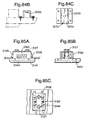
- 84A to 84C show, in three different views, a guide channel-forming attachment 3230 which can be screwed, which would have advantages for the insertion of channels 3233 for a seal 3233. It would not work with sliders in the tool.
- the central fixation attachment 3293 can be produced by ejection (sheet metal part) or casting (die casting, plastic injection molding). The fixing plug 123 described in the previous embodiment (Figs. 82A to 82E) would not be necessary here.
- FIGS. 85A to 85C show, in three different views, an embodiment in which a particularly large load capacity is achieved by a four-fold arrangement of clipping plates 3136.
- the U-part for forming the guide channel 3128 is bolted here. Overlying U-legs are recessed in the back of the head portion 3124. The Klipsplatten lead between the Verschraubungszylindern 3127 and in the inner wall of the U-part.
- Figure 86A shows, in an axial sectional view, a folding lever closure 3210 arranged in a rectangular aperture in a thin wall, such as door leaf 3216, the folding lever closure defining the outer edge of the thin wall 3216 on one, outer side Opening overlying head portion 3224, from which a breakthrough protruding in the mounted position fuselage part 3226 protrudes from the protruding in the direction of its outer surface retaining elements 3236, the free end of the inclined surface 3238 for play-free support of the fuselage 3226 on the edge or the edge of Breakthrough of the other, inner side of the thin wall 3216.
- Fuselage 3226 and support member 3236 are here two separate parts, wherein the support member 3236 are mounted in the torso part axially displaceable (or rotatable) in a direction transverse to the longitudinal extent of the folding lever against spring force.
- Body 3226 and head 3224 are integral.
- an actuatable folding lever 3222 pivoted about an axis 3221 in the body portion 3226 pivots outwardly through the tongue 3270 of a cylinder lock 3254 in the position shown in Fig. 86A where the tongue encounters a projection of the body part 3226 rests.
- a closed position engages a against spring force displaceable latch-like latch 3252 formed by the door frame 3250 Schugriff Chemistry 3274, which is here formed by a hook, which in turn is fastened with a holding element according to the invention 3235 on the door frame 3250 inserted.
- FIG. 86B shows a front view of the closure according to FIG. 86A
- FIG. 86C shows a side view
- FIG. 86D shows a view from above of the closure 3210 installed in the door leaf 3216 and extending into the bent space formed by the door leaf 3216 and door frame 3250.
- FIG. 86E shows a perspective view of the part of the locked closure which is visible from the outside
- FIG. 86F shows the opened closure in the same view, in which state a projection 3211 connected in a torsionally rigid manner with the lever 3222 the force of the spring 3241 pulls the latch bolt 3252 so far that the latch of the hook or the return surface 3274 free and the door can be opened. This position is shown in FIG. 86F.
- FIG. 86G shows an exploded view of the individual parts of the closure according to the invention.
- a blocking plug 3223 engages a recess 3225 of the retaining element 3236 and represents a travel limit for the retaining element 3236.
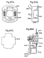
- FIGS. 87A, 87B which can be subjected to particularly heavy loads
- the cut-out, see FIG. 87C is somewhat more complicated, that is to say deviating from the rectangular shape.
- the four associated retaining elements 3336 are present as two pairs of two opposing elements 3336 and aligned in the direction of the tongue extension, in contrast to the embodiment according to FIG. 86G, where the retaining elements 3236 are arranged perpendicular to this direction.
- FIGS. 88A to 88G show, in various views, a rotary latch or sash fastener which is fastened by means of holding elements according to the invention in an opening in a thin wall, such as a sheet-metal door.
- Figure 88A shows an axial section through the cam lock 3410 installed in a rectangular aperture 3478 in the door leaf 3416.
- a cam or thumb latch 3452 engages behind a rear surface formed by the door frame 3450.
- Above and below the Bearing housing for the drive shaft for the rotary latch 3452 are located in the channels 3439 accommodated holding elements 3436, which invest in pushing through the body portion 3426 through the rectangular opening 3478 in the door leaf 3416 behind the breakthrough edges on the inner surface of the door panel and hold the shutter 3410.
- Tongue 3450 and body portion are formed, as shown in FIG. 88D, another axial sectional view, such that without disassembly of the tongue portion 3452, the closure through the aperture 3478 first with the tongue and then with the retaining members against the spring force of the compression springs 3444 in the channel 3439 can recede until the relatively steep inclined surface having holding surface 3438 is reached.
- the steepness of this inclined surface is such that even when high forces occur, a retreating along this surface does not occur, and that even with strong from the tongue emanating pressure or Knittel latern the holder does not loosen again.
- FIG. 88B shows a plan view of the head part or flange 3424 with the socket wrench drive 3413 shown here for a shaft 3415 results in an actuation possibility, wherein the shaft 3415 carries at its protruding from the body part 3426 end in a conventional manner a square for a rotary latch 3452, which by means of a cap screw which can be screwed into a corresponding thread in the shaft 3415 is, is being held.
- Fig. 88C shows a view of the back of the closure.
- 88E shows a side view in the direction of the tongue
- FIGS. 88F and 88G show two perspective views for further explanation of the construction of the closure device 3416 according to the invention.
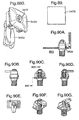
- Fig. 90A shows a pull-turn-lock closure according to the invention, which can be inserted in a breakthrough 3578 in a thin wall such as a sheet metal door 3516, wherein the head part 3524 supports a shaft 3515 with actuating button, at the same time go from the head part 3524 two a fuselage part 3426 forming channels for holding elements 3536 with associated spring 3544, with two counter-rotating and below and above the shaft 3515 arranged holding elements 3536 provide sufficient stability to ensure that at the end of the shaft 3515 via a pulley or a spring a turn-lock 3552 is attached.
- the rotary latch 3552 is linked to the actuating knob on the shaft 3515, that in the first part of the rotation (when opening) a lifting movement away from the knob 3515, after a partial rotation then due to the friction also a rotational movement occurs, the rotary latch of the in Fig. 90A, an axial sectional view, of the shutter state shown moves upward, to which the corresponding L-shape formed by an opening in the frame accommodates this movement of the tongue.
- the thin wall 3516 may be part of a drawer which is extendable from a drawer frame 3550.
- Fig. 90E Stops on the housing edge on which slide the tongue 3552 along, see Fig. 90E, a view from behind, causes a Drehwegbegrenzung for the latch 3552 between z. B. 90 ° closed position as in Fig. 50G, and the open position, Fig. 90F further illustrates the structure and function of the closure. It is possible, as shown in FIG. 91, to optionally upturn the tongue 3552 so as to accommodate a distance match between the supporting wall and the return surface to be gripped.
- Figs. 93A to 93K It is illustrated in Figs. 93A to 93K how the closure already described may still be provided with a fingernail which facilitates the mounting of a drawer if it is jammed. Otherwise, the shutter does not differ from the embodiment described with reference to Figs. 90A to 90K. However, it has arrangements of 2 x 2 fasteners, as shown in Fig. 93K clearly. It is therefore possible to absorb even greater forces with this closure than with the closure according to the preceding embodiment.
- the invention can be evaluated commercially in control cabinet construction.
Landscapes
- Engineering & Computer Science (AREA)
- Mechanical Engineering (AREA)
- Hinges (AREA)
- Closing And Opening Devices For Wings, And Checks For Wings (AREA)
- Connection Of Plates (AREA)
- Closures For Containers (AREA)
- Lock And Its Accessories (AREA)
- Clamps And Clips (AREA)
- Insertion Pins And Rivets (AREA)
- Snaps, Bayonet Connections, Set Pins, And Snap Rings (AREA)
Applications Claiming Priority (2)
| Application Number | Priority Date | Filing Date | Title |
|---|---|---|---|
| DE200420003238 DE202004003238U1 (de) | 2004-02-27 | 2004-02-27 | Klipsbefestigung für die Schnellmontage von Beschlageinrichtungen, wie Schwenkhebelverschlüsse, Scharnierteile in Durchbrüchen in einer dünnen Wand |
| EP20050715593 EP1723298B1 (fr) | 2004-02-27 | 2005-02-28 | Fermeture a fixer dans des ouvertures menagees dans une paroi mince |
Related Parent Applications (1)
| Application Number | Title | Priority Date | Filing Date |
|---|---|---|---|
| EP20050715593 Division EP1723298B1 (fr) | 2004-02-27 | 2005-02-28 | Fermeture a fixer dans des ouvertures menagees dans une paroi mince |
Publications (2)
| Publication Number | Publication Date |
|---|---|
| EP1857616A2 true EP1857616A2 (fr) | 2007-11-21 |
| EP1857616A3 EP1857616A3 (fr) | 2008-04-30 |
Family
ID=34745551
Family Applications (2)
| Application Number | Title | Priority Date | Filing Date |
|---|---|---|---|
| EP20070011329 Withdrawn EP1857616A3 (fr) | 2004-02-27 | 2005-02-28 | Fermeture à fixer dans des ouvertures menagées dans une paroi mince |
| EP20050715593 Expired - Lifetime EP1723298B1 (fr) | 2004-02-27 | 2005-02-28 | Fermeture a fixer dans des ouvertures menagees dans une paroi mince |
Family Applications After (1)
| Application Number | Title | Priority Date | Filing Date |
|---|---|---|---|
| EP20050715593 Expired - Lifetime EP1723298B1 (fr) | 2004-02-27 | 2005-02-28 | Fermeture a fixer dans des ouvertures menagees dans une paroi mince |
Country Status (12)
| Country | Link |
|---|---|
| US (1) | US8667819B2 (fr) |
| EP (2) | EP1857616A3 (fr) |
| JP (1) | JP4701233B2 (fr) |
| KR (1) | KR100984564B1 (fr) |
| CN (1) | CN1926295B (fr) |
| AU (1) | AU2005217739B2 (fr) |
| BR (1) | BRPI0508196A (fr) |
| DE (2) | DE202004003238U1 (fr) |
| ES (1) | ES2370130T3 (fr) |
| MX (1) | MXPA06009730A (fr) |
| RU (1) | RU2418141C2 (fr) |
| WO (1) | WO2005083209A1 (fr) |
Families Citing this family (22)
| Publication number | Priority date | Publication date | Assignee | Title |
|---|---|---|---|---|
| DE202004003238U1 (de) | 2004-02-27 | 2005-07-07 | Ramsauer, Dieter | Klipsbefestigung für die Schnellmontage von Beschlageinrichtungen, wie Schwenkhebelverschlüsse, Scharnierteile in Durchbrüchen in einer dünnen Wand |
| AU2005206311B2 (en) * | 2004-01-26 | 2009-08-06 | Dieter Ramsauer | Hinge for mounting in an opening |
| DE202006002592U1 (de) | 2006-02-18 | 2007-06-28 | Ramsauer, Dieter | Verspannbare Befestigungseinrichtung |
| US7946633B2 (en) * | 2007-09-10 | 2011-05-24 | Interlock Usa, Inc. | Low friction adjustable roller pin |
| US8220846B2 (en) * | 2008-08-15 | 2012-07-17 | Vision Industries Group, Inc. | Latch for tiltable sash windows |
| US8336927B2 (en) | 2008-08-15 | 2012-12-25 | Luke Liang | Tilt latch with cantilevered angular extension |
| DE202010006525U1 (de) * | 2010-05-07 | 2011-10-05 | Dirak Dieter Ramsauer Konstruktionselemente Gmbh | In eine Mulde einschwenkbarer Betätigungshebel |
| DE102011002216B3 (de) * | 2011-04-21 | 2011-12-01 | Simonswerk, Gesellschaft mit beschränkter Haftung | Anordnung von zwei Bauteilen, insbesondere Bandteilen |
| EP2944747B1 (fr) * | 2014-05-12 | 2018-06-13 | Industrilås I Nässjö AB | Serrure pour opération manuelle droite ou gauche |
| CN105133964A (zh) * | 2015-09-23 | 2015-12-09 | 万沙电气有限公司 | 电表箱隐形内扣式挂锁鼻带铅封把手锁 |
| CN106739636B (zh) * | 2015-11-25 | 2018-12-11 | 叶秀锋 | 一种单手掣锁夹 |
| DE202017001165U1 (de) * | 2017-03-06 | 2018-06-08 | Dieter Ramsauer | Snapverbinder |
| CN108193869B (zh) * | 2018-01-10 | 2024-07-09 | 梅苏鸿 | 一种锁定器 |
| CN110857711A (zh) * | 2018-08-24 | 2020-03-03 | 泷源制造株式会社 | 面板固定件 |
| RU2695978C1 (ru) * | 2018-12-06 | 2019-07-29 | Общество с ограниченной ответственностью "БОРДЕР" | Замок с функцией блокировки выдвинутого засова при извлечении цилиндрового механизма |
| US11124988B1 (en) * | 2019-01-22 | 2021-09-21 | Olympus Lock, Inc. | Electronic rim cylinder cabinet door and drawer lock |
| JP7199983B2 (ja) * | 2019-01-31 | 2023-01-06 | タキゲン製造株式会社 | ワンタッチ取付ハンドル |
| CN110005259A (zh) * | 2019-03-27 | 2019-07-12 | 宁波生久柜锁有限公司 | 快速安装平面锁 |
| DE102020125243B3 (de) * | 2020-09-28 | 2022-03-31 | Dieter Ramsauer | Spannverschluss zur werkzeuglosen Montage und System zur werkzeuglosen Montage des Spannverschlusses |
| US12221810B2 (en) | 2021-07-09 | 2025-02-11 | Hoffman Enclosures Inc. | Apparatus and methods for securing an equipment cabinet |
| KR102794253B1 (ko) | 2022-11-22 | 2025-04-14 | 김대영 | 숙면을 제공하는 목침 |
| CN115977466A (zh) * | 2023-01-17 | 2023-04-18 | 希美克(广州)实业有限公司 | 一种门窗执手的快装固定座 |
Citations (2)
| Publication number | Priority date | Publication date | Assignee | Title |
|---|---|---|---|---|
| EP0258491A1 (fr) | 1986-08-23 | 1988-03-09 | HUWIL-Werke GmbH Möbelschloss- u. Beschlagfabriken | Système de fixation d'un cylindre pour fermeture |
| US5435159A (en) | 1989-10-03 | 1995-07-25 | Ramsauer; Dieter | Lock housing with flange for fitting in an aperture in a thin wall like a sheet metal cupboard door or sheet metal casing cover |
Family Cites Families (16)
| Publication number | Priority date | Publication date | Assignee | Title |
|---|---|---|---|---|
| DE342387C (de) * | 1921-01-22 | 1921-10-17 | Damm & Ladwig | Befestigung fuer Einsatzschloesser |
| US1426239A (en) * | 1921-11-15 | 1922-08-15 | Witzberger Heating Appliances | Spring stove bolt |
| BE883121A (fr) * | 1980-05-06 | 1980-11-06 | Lowe Et Fletcher Belge S A | Serrure a fixation rapide |
| DE3147854C2 (de) * | 1981-03-06 | 1987-01-02 | S. Franzen Söhne (GmbH & Co), 5650 Solingen | Befestigungsvorrichtung für Einbauschlösser an Koffern |
| US5249443A (en) * | 1992-09-08 | 1993-10-05 | Loctec Corporation | Front-installed dual cam lock with pivoting cams |
| US5251467A (en) * | 1992-09-08 | 1993-10-12 | Loctec Corporation | Front-installed cam lock |
| US5445159A (en) * | 1994-11-21 | 1995-08-29 | Cheng; Wang | Minimally invasive method to determine the left ventricular pressure waveform |
| US6023953A (en) * | 1998-01-30 | 2000-02-15 | Southco, Inc. | Slam latch with opposing slides |
| US6553796B2 (en) * | 2000-05-19 | 2003-04-29 | Compx International Inc. | Electrical panel lock with locking plug head |
| WO2002003906A2 (fr) * | 2000-06-29 | 2002-01-17 | Nikolay Grigorjevich Lyapko | Applicateur modulaire destine a la reflexotherapie |
| US6508092B1 (en) * | 2001-01-24 | 2003-01-21 | The Eastern Company | Snap-in mount for CAM locks and the like |
| FR2828227B3 (fr) * | 2001-07-31 | 2003-09-26 | Ronis Sa | Serrure composee d'un corps pouvant etre fixe dans un ajour d'une tole |
| US7401043B2 (en) * | 2001-09-03 | 2008-07-15 | Michihiro Sato | Method and system for issuing securities and fixed rate financing instruments, method for establishing a market with the system |
| FR2833291B1 (fr) * | 2001-12-11 | 2007-02-23 | Ronis Sa | Serrure auto-clipsable dans un ajour d'un support |
| DE202004003238U1 (de) | 2004-02-27 | 2005-07-07 | Ramsauer, Dieter | Klipsbefestigung für die Schnellmontage von Beschlageinrichtungen, wie Schwenkhebelverschlüsse, Scharnierteile in Durchbrüchen in einer dünnen Wand |
| EP1709270B1 (fr) | 2004-01-26 | 2012-04-25 | Dieter Ramsauer | Fixation de pinces pour le montage de dispositifs de ferrures, tels que fermetures, elements de charniere, poignees dans des passages au travers d'une paroi mince |
-
2004
- 2004-02-27 DE DE200420003238 patent/DE202004003238U1/de not_active Expired - Lifetime
-
2005
- 2005-02-28 AU AU2005217739A patent/AU2005217739B2/en not_active Ceased
- 2005-02-28 US US10/590,638 patent/US8667819B2/en not_active Expired - Fee Related
- 2005-02-28 EP EP20070011329 patent/EP1857616A3/fr not_active Withdrawn
- 2005-02-28 MX MXPA06009730A patent/MXPA06009730A/es unknown
- 2005-02-28 RU RU2006130420/12A patent/RU2418141C2/ru not_active IP Right Cessation
- 2005-02-28 BR BRPI0508196-3A patent/BRPI0508196A/pt not_active Application Discontinuation
- 2005-02-28 KR KR1020067020071A patent/KR100984564B1/ko not_active Expired - Fee Related
- 2005-02-28 WO PCT/EP2005/002083 patent/WO2005083209A1/fr not_active Ceased
- 2005-02-28 DE DE200511000136 patent/DE112005000136A5/de not_active Withdrawn
- 2005-02-28 JP JP2007500179A patent/JP4701233B2/ja not_active Expired - Fee Related
- 2005-02-28 CN CN2005800062295A patent/CN1926295B/zh not_active Expired - Lifetime
- 2005-02-28 ES ES05715594T patent/ES2370130T3/es not_active Expired - Lifetime
- 2005-02-28 EP EP20050715593 patent/EP1723298B1/fr not_active Expired - Lifetime
Patent Citations (2)
| Publication number | Priority date | Publication date | Assignee | Title |
|---|---|---|---|---|
| EP0258491A1 (fr) | 1986-08-23 | 1988-03-09 | HUWIL-Werke GmbH Möbelschloss- u. Beschlagfabriken | Système de fixation d'un cylindre pour fermeture |
| US5435159A (en) | 1989-10-03 | 1995-07-25 | Ramsauer; Dieter | Lock housing with flange for fitting in an aperture in a thin wall like a sheet metal cupboard door or sheet metal casing cover |
Also Published As
| Publication number | Publication date |
|---|---|
| US8667819B2 (en) | 2014-03-11 |
| ES2370130T3 (es) | 2011-12-13 |
| EP1723298B1 (fr) | 2014-01-08 |
| EP1857616A3 (fr) | 2008-04-30 |
| JP2007524017A (ja) | 2007-08-23 |
| EP1723298A1 (fr) | 2006-11-22 |
| CN1926295B (zh) | 2011-03-23 |
| KR100984564B1 (ko) | 2010-10-01 |
| AU2005217739A1 (en) | 2005-09-09 |
| MXPA06009730A (es) | 2007-03-26 |
| RU2006130420A (ru) | 2008-04-10 |
| WO2005083209A1 (fr) | 2005-09-09 |
| US20080060401A1 (en) | 2008-03-13 |
| DE112005000136A5 (de) | 2007-07-26 |
| KR20060135843A (ko) | 2006-12-29 |
| CN1926295A (zh) | 2007-03-07 |
| RU2418141C2 (ru) | 2011-05-10 |
| JP4701233B2 (ja) | 2011-06-15 |
| AU2005217739B2 (en) | 2010-05-27 |
| DE202004003238U1 (de) | 2005-07-07 |
| BRPI0508196A (pt) | 2007-08-14 |
Similar Documents
| Publication | Publication Date | Title |
|---|---|---|
| EP1845222B1 (fr) | Fixation par clip pour le montage de dispositifs d'armatures, comme fermeture, partie de charnière, poignée dans des percées d'un mur fin | |
| EP1709267B1 (fr) | Fixation par clipsage pour le montage rapide de dispositifs d'armature, des fermetures a levier pivotant ou des pieces de charniere par exemple, dans des ouvertures menagees dans une paroi mince | |
| EP1723298A1 (fr) | Fermeture a fixer dans des ouvertures menagees dans une paroi mince | |
| EP1131521A1 (fr) | Fermeture a verrou rotatif avec unite de traction | |
| EP0261267A1 (fr) | Fermeture de barre pour portes d'armoires en tôle | |
| EP1857688B1 (fr) | Fixation par clipsage ou encliquetage permettant de fixer une paroi mince sur un support de paroi | |
| DE3631516C2 (fr) | ||
| EP1711672B1 (fr) | Charniere a monter dans une ouverture | |
| WO1996010679A1 (fr) | Fermeture a barre | |
| DE10292961B4 (de) | Stangenverschluß | |
| EP1917413B1 (fr) | Dispositif de fermeture pour realiser le verrouillage multipoint de portes ou de parties de paroi dans des boitiers ou des armoires | |
| WO2005113923A1 (fr) | Poignee encastree | |
| EP1709268A1 (fr) | Serrure a cremone a monter dans une ouverture realisee dans une paroi mince (dispositif a clipsage indirect) | |
| DE202004018340U1 (de) | Schnappbefestigung zur Festlegung eines Beschlages oder einer dünnen Wand an einen Beschlagträger oder Wandträger | |
| DE202005001315U1 (de) | Klipsbefestigung für die Schnellmotage von Beschlageinrichtungen, wie Schwenkhebelverschlüsse, Scharnierteile in Durchbrüchen in einer dünnen Wand | |
| EP1119675B1 (fr) | Systeme de fermeture a loquet | |
| DE20105684U1 (de) | Schnappverschluß mit Drehbetätigung | |
| DE19621619C2 (de) | Türschloß | |
| DE202004016009U1 (de) | Klips- oder Schnappbefestigung zur Festlegung einer dünnen Wand an einen Wandträger | |
| DE202004004066U1 (de) | Verschluß mit Klemmbefestigung | |
| DE202004016010U1 (de) | Schnappbefestigung zur Festlegung einer dünnen Wand an einen Wandträger | |
| EP1012433A1 (fr) | Tige de fermeture d'un dispositif de fermeture |
Legal Events
| Date | Code | Title | Description |
|---|---|---|---|
| PUAI | Public reference made under article 153(3) epc to a published international application that has entered the european phase |
Free format text: ORIGINAL CODE: 0009012 |
|
| AC | Divisional application: reference to earlier application |
Ref document number: 1723298 Country of ref document: EP Kind code of ref document: P |
|
| AK | Designated contracting states |
Kind code of ref document: A2 Designated state(s): AT BE BG CH CY CZ DE DK EE ES FI FR GB GR HU IE IS IT LI LT LU MC NL PL PT RO SE SI SK TR |
|
| PUAL | Search report despatched |
Free format text: ORIGINAL CODE: 0009013 |
|
| AK | Designated contracting states |
Kind code of ref document: A3 Designated state(s): AT BE BG CH CY CZ DE DK EE ES FI FR GB GR HU IE IS IT LI LT LU MC NL PL PT RO SE SI SK TR |
|
| 17P | Request for examination filed |
Effective date: 20080626 |
|
| AKX | Designation fees paid |
Designated state(s): AT BE BG CH CY CZ DE DK EE ES FI FR GB GR HU IE IS IT LI LT LU MC NL PL PT RO SE SI SK TR |
|
| 17Q | First examination report despatched |
Effective date: 20091230 |
|
| STAA | Information on the status of an ep patent application or granted ep patent |
Free format text: STATUS: THE APPLICATION IS DEEMED TO BE WITHDRAWN |
|
| 18D | Application deemed to be withdrawn |
Effective date: 20150901 |