EP1857617A2 - Zahnradschloss mit Halterung für Metallrahmenstrukturen - Google Patents
Zahnradschloss mit Halterung für Metallrahmenstrukturen Download PDFInfo
- Publication number
- EP1857617A2 EP1857617A2 EP07251509A EP07251509A EP1857617A2 EP 1857617 A2 EP1857617 A2 EP 1857617A2 EP 07251509 A EP07251509 A EP 07251509A EP 07251509 A EP07251509 A EP 07251509A EP 1857617 A2 EP1857617 A2 EP 1857617A2
- Authority
- EP
- European Patent Office
- Prior art keywords
- lock
- closure plate
- descending
- rod
- projection
- Prior art date
- Legal status (The legal status is an assumption and is not a legal conclusion. Google has not performed a legal analysis and makes no representation as to the accuracy of the status listed.)
- Withdrawn
Links
Images


Classifications
-
- E—FIXED CONSTRUCTIONS
- E05—LOCKS; KEYS; WINDOW OR DOOR FITTINGS; SAFES
- E05B—LOCKS; ACCESSORIES THEREFOR; HANDCUFFS
- E05B9/00—Lock casings or latch-mechanism casings ; Fastening locks or fasteners or parts thereof to the wing
- E05B9/08—Fastening locks or fasteners or parts thereof, e.g. the casings of latch-bolt locks or cylinder locks to the wing
- E05B9/084—Fastening of lock cylinders, plugs or cores
-
- E—FIXED CONSTRUCTIONS
- E05—LOCKS; KEYS; WINDOW OR DOOR FITTINGS; SAFES
- E05B—LOCKS; ACCESSORIES THEREFOR; HANDCUFFS
- E05B9/00—Lock casings or latch-mechanism casings ; Fastening locks or fasteners or parts thereof to the wing
- E05B9/08—Fastening locks or fasteners or parts thereof, e.g. the casings of latch-bolt locks or cylinder locks to the wing
-
- E—FIXED CONSTRUCTIONS
- E05—LOCKS; KEYS; WINDOW OR DOOR FITTINGS; SAFES
- E05B—LOCKS; ACCESSORIES THEREFOR; HANDCUFFS
- E05B17/00—Accessories in connection with locks
- E05B17/20—Means independent of the locking mechanism for preventing unauthorised opening, e.g. for securing the bolt in the fastening position
- E05B17/2084—Means to prevent forced opening by attack, tampering or jimmying
- E05B17/2092—Means responsive to tampering or attack providing additional locking
-
- E—FIXED CONSTRUCTIONS
- E05—LOCKS; KEYS; WINDOW OR DOOR FITTINGS; SAFES
- E05C—BOLTS OR FASTENING DEVICES FOR WINGS, SPECIALLY FOR DOORS OR WINDOWS
- E05C9/00—Arrangements of simultaneously actuated bolts or other securing devices at well-separated positions on the same wing
- E05C9/02—Arrangements of simultaneously actuated bolts or other securing devices at well-separated positions on the same wing with one sliding bar for fastening when moved in one direction and unfastening when moved in opposite direction; with two sliding bars moved in the same direction when fastening or unfastening
- E05C9/021—Arrangements of simultaneously actuated bolts or other securing devices at well-separated positions on the same wing with one sliding bar for fastening when moved in one direction and unfastening when moved in opposite direction; with two sliding bars moved in the same direction when fastening or unfastening with rack and pinion mechanism
- E05C9/023—Arrangements of simultaneously actuated bolts or other securing devices at well-separated positions on the same wing with one sliding bar for fastening when moved in one direction and unfastening when moved in opposite direction; with two sliding bars moved in the same direction when fastening or unfastening with rack and pinion mechanism between a lock cylinder and the bar
-
- E—FIXED CONSTRUCTIONS
- E05—LOCKS; KEYS; WINDOW OR DOOR FITTINGS; SAFES
- E05B—LOCKS; ACCESSORIES THEREFOR; HANDCUFFS
- E05B17/00—Accessories in connection with locks
- E05B17/0012—Accessories in connection with locks for lock parts held in place before or during mounting on the wing
Definitions
- This invention consists of a lock for embedding in metal frames manufactured with commercial profiles. Specifically it is a lock with latch and handle, comprising a cogwheel assembly mounted in such a way that its last stage is an input wheel and its first stage is an output wheel that is activated by the eccentricity of a key lock cylinder, positioned coaxially to this input wheel and is mounted "in situ” using a screw placed transversal to the cylinder, from the front of the lock.
- This lock also includes a solid descending closure plate that has terminals to engage the latches that activate the upper and lower locking bolts. The vertical plane of this descending plate forms a cogged rack and the plate operates between the upper and lower latch opening and closing positions, respectively.
- the locks used with commercial metal profile frames are conditioned in terms of the small space available in the width of the frame in which the lock is embedded.
- the mechanism of a lock of this type should combine the greatest possible security with the use of the least possible number of parts, which should be simple and economical, offering smooth and reliable operation and favouring an overall design that is compact and occupies the least possible space.
- the most common device used in this field is one in which the cogwheel assembly operates directly on the latch and it is the latch that, as it moves, operates the descending closure plate.
- This solution tends to make it difficult to achieve mechanisms that fit in a lock case suitable for the narrowness of the frame in which it has to be embedded, which leads to using thinner and smaller parts, which in turn results in a weaker mechanism.
- this invention is for a lock for embedding in metal frames manufactured with commercial profiles, with a closing system, as previously indicated, of the latch and handle type, and comprising a cogwheel assembly mounted in such a way that its last stage is an output wheel and its first stage is an input wheel that is activated by the eccentricity of a key lock cylinder, positioned coaxially to the input wheel and mounted "in situ” using a screw placed transversal to the cylinder, from the front of the lock.
- This lock also includes a solid descending closure plate that has terminals to engage the latches that activate the upper and lower locking bolts. The vertical plane of this descending plate forms a cogged rack that and the plate operates between the upper and lower latch opening and closing positions, respectively.
- the output cogwheel engages with the cogged rack of the descending closure plate, this output wheel operating in a hollow in the edge of the descending closure plate. Furthermore, it includes a handle retraction function via the descending closure plate and it also has the means to automatically hold the cogwheel assembly in place in the absence of the lock's cylinder. In contrast with other mechanisms that exist in this field, in the proposed solution the cogwheel assembly acts directly on the descending closure plate, through the cogged rack, at it is the descending closure plate, as it moves, that subsequently activates the operating movements of the closing latch or lever.
- Another particularity of the invention is that the mechanisms that retract the handle, through the descending closure plate and together with the input wheel.
- These mechanisms consist of a flat, vertical rod that, capable of sliding whilst attached to one side of the lock case, is guided between an upper, or pre-active position, to a lower, or inhibited position.
- This rod has a top face, a lug projecting from the front bottom, transversal to the rod's plane, and a tooth projecting from the rear vertical edge of the rod, noticeably in the same plane.
- the top face, in pre-active position faces and is adjacent to the radial projection of a rotating cam, or follower rod, which, with its radial shaft, retracts the handle.
- the lug travels in an opening in the front edge of the descending closure plate in such a way that, when the latter is in its lower and upper positions, the lug touches the top and bottom of the opening, respectively.
- the bottom edge of the tooth is horizontal and the top edge is sloped.
- this tooth is positioned, respectively, away from or in the path of the rotational operating route of the rear projection of the input wheel, when this is activated during opening by the eccentricity of the lock cylinder.
- the workings of this solution consists basically in that when the descending closure plate has risen to the point in which the latch has been completely retracted, the lower end of its front opening has pushed the rod lug along the front opening of the descending closure plate, pulling the rod itself up until the top face lies under the radial projection of the follower rod and the lower horizontal face of the tooth on the rod is inserted in the engaging rotational path, activated by the eccentricity of the lock cylinder.
- this consists in a vertically sliding tab that moves between an upper, or active position, propelled by a spring, and an lower, or inhibited position, contrary to the spring propulsion.
- a lateral projection In the lower part of the tab there is a lateral projection, the top of which forms a peak and in its upper active position the tab is positioned in a housing on the outside edge of the input wheel of the cogwheel assembly, whilst the peak of the lateral projection enters the longitudinal hole in the lock case that houses the transversal screw that screws into the lock cylinder, when this is mounted.
- the tab and lateral projection remain, respectively, outside the input wheel housing and the longitudinal hole in the lock case.
- the descending closure plate has a downward, front to back, stepped sliding mechanism formed by a central oblique section that forms vertically, at its front, or superior, and rear or inferior ends an upper ascending projection and a lower descending projection, ending in hollows that take the corresponding spigot with the latch that slides along this stepped slide.
- the upper projection has a rear vertical border and in the lower projection the hollow is linked to the upper edge of the oblique section of the stepped slide by way of a rear vertical border with a longitude that, together with effect resulting from the cogwheel assembly, provides an empty run which is noticeably less than the vertical operative run of the rod during handle retraction.
- This configuration allows the rear vertical border (of the upper projection of the stepped slide) to act as a stop that prevents retraction of the descending closure plate when this is attempted with the plate is in its lower position (lock closed); on the other hand, the empty run linked to the rear vertical border (of the lower projection of the stepped slide) enables the relative play necessary for the rod to achieve handle retraction.
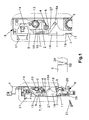
- Fig. 1 shows a perspective of the invented lock, seen from the front with the lateral cover removed, in open position and with the handle extended.
- the transversal screw (21) and the cylinder (5) are shown enlarged, the latter only partially, in orthogonal transformation and seen from the side.
- This figure also shows an enlargement, in orthogonal transformation, of the upper part of the mechanism, seen from the front of the uncovered side.
- Fig. 2 is a side view, in orthogonal transformation, of the lock in Fig. 1, but with the lock closed.
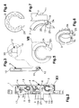
- Fig. 3 is a perspective view of the flat vertical rod (7), which includes an enlargement of the tooth (12).
- Fig. 4 shows the input wheel (3) seen in Fig. 2, showing the cogged side.
- Fig. 5 is a rear view of the input wheel seen in Fig. 4.
- Fig. 6 is a perspective view from the rear of the input wheel (3) shown in Figs. 4 and 5.
- Fig. 7 is an enlarged view of detail VII marked in Fig. 5.
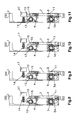
- Figs. 8 to 11 illustrate the operational sequence for retracting the handle (17), showing the lock in Fig. 1, seen from the opposite side and with the latch (16) retracted.
- Fig. 8 shows the initial position, in which the cylinder (5) has not yet begun to turn for the retraction operation.
- Fig. 9 the cylinder has begun to turn, but the input wheel (3) has not.
- Fig. 10 it can be seen that the handle (17) has begun to retract, and Fig. 11 shows the complete retraction of the handle (17).
- Figures 12 and 13 also show the handle (17) retraction operational sequence, but from the other side of the lock, in order to better illustrate the relative action of the lug (11) and the rod (7) in the opening (18) of the descending closure plate (1).
- Fig. 12 is an enlargement of the area marked XII in Fig. 2, showing a section that contains the axis of the longitudinal screw hole (26) and the spring (23), with the cylinder (5), cross-sectioned to demonstrate the eccentricity (5a) and the threaded bore hole (5b).
- Fig. 13 is the same as fig. 12, but shows the rod (7) in position to be moved upwards to retract the handle.
- Fig. 14 is a representation similar to fig. 12, but referring to the means of automatic retention of the mounted cogwheel assembly. It shows the transversal screw (21) commencing its entry into the screw hole (26) of the cylinder (5), which has already been positioned in place. The presence of part of the descending closure plate (1) is not shown in this figure.
- Fig. 15 is similar to Fig. 14, but it shows the transversal screw (21) now inside the screw hole (5b) of the cylinder (5).
- Fig. 16 shows the descending closure plate (1) seen from the same side as in Figs. 1 and 2.
- Fig. 17 is an enlargement of section XVII marked in Fig. 16.
- the attached plans illustrate a preferential realisation of the invention for a lock to be embedded in metal frames manufactured with commercial profiles, of the latch (16) and handle (17) type, and which, as shown in Fig. 1, comprises a cogwheel assembly mounted in such a way that its last stage is an output wheel (4) and its first stage is an input wheel (3) that is activated by the eccentricity (5a) of a key lock cylinder (5), positioned coaxially to this input wheel (3) and mounted "in situ” using a screw (21) placed transversally to and from the front of the lock.
- This lock also includes a solid descending closure plate (1) that has terminals to engage the latches that activate the upper and lower locking bolts.
- the vertical plane of this descending closure plate (1) forms a cogged rack (2) and the descending closure plate (1) operates between the upper and lower latch (16) opening and closing positions, respectively.
- Fig. 1 illustrates one of the purposes of the invention, which is to have the output cogwheel (4) engage with the cogged rack (2) of the descending closure plate (1), the output wheel (4) operating in a hollow (6) formed in the edge of the descending closure plate (1). Furthermore, it includes handle (17) retraction functions via the descending closure plate (1) and it also has the means to automatically hold the cogwheel assembly in the absence of the lock's cylinder (5).
- the output wheel (4) is located in said hollow (6) and acts on the thickness of the descending closure plate (1), which makes it possible to build a narrower lock case (8) which is, therefore, more suitable to be embedded in the narrow frontal width of a metal frame.
- FIGs. 3 to 13 Another particularity of the invention is illustrated in Figs. 3 to 13 and it refers to the mechanisms that retract the handle (17) due to the eccentricity (5a) of the cylinder (5) and through the descending closure plate (1), together with the input wheel (3).
- These mechanisms consist of a flat, vertical rod (7) (Fig. 3) that, being capable of sliding whilst attached to one side (9) of the lock case (8), is guided between an upper, or pre-active position (Figs. 1, 8, 9 and 13), to a lower, or inhibited position (Figs. 2 and 12).
- This rod (7) has a top face (10), a lug (11) projecting from the front bottom, transversal to the rod's plane, and a tooth (12) projecting from the rear vertical edge of the rod, noticeably in the same plane.
- the top face (10), in pre-active position, faces and is adjacent to a radial projection (15) of a rotating cam, or follower rod (13), which, with its radial shaft (14), retracts the handle (17).
- the lug (11) travels in an opening (18) in the front edge of the descending closure plate (1) in such a way that, when the latter is in its lower and upper positions, the lug (11) touches the top and bottom of the opening (18), respectively.
- the bottom edge of the tooth (12) is horizontal (19) and the top edge is sloped (20) and with respect to the aforementioned lower or inhibited, and upper or pre-active positions of the rod (7), the tooth (12) is positioned, respectively, away from (figs. 2 and 12) or in the path of (Figs. 10, 11 and 13) the rotational operating run of the rear projection (3a) of the input wheel (3) when it is activated, during the opening turn, by the eccentricity (5a) of the lock cylinder (5). That is, after two clockwise turns of the key in the cylinder (5) (Figs. 8 and 13) (remember that in Fig.
- Another of the purposes of this invention concerns the system for automatically holding the cogwheel assembly in place in the absence the lock cylinder (5).
- This consists in a vertically sliding tab (22) that moves between an upper, or active position, propelled by a spring (23), and a lower, or inhibited position, opposing the spring (23) propulsion.
- the tab (22) In the lower part of the tab (22) there is a lateral projection (24), the top of which forms a peak and in its upper active position the tab (22) is positioned in a housing (25) on the outside edge of the input wheel (3) of the cogwheel assembly, whilst the lateral projection (24) is inserted inside the longitudinal screw hole (26) in the lock case (8), which takes the transversal screw (21) that screws into the lock cylinder (5), when this is mounted. In its lower, inhibited position, the tab (22) and lateral projection (24) are positioned, respectively, outside the input wheel (3) housing (25) and the longitudinal hole (26) in the lock case (8).
- Figs 14 and 15 Its configuration and functioning are illustrated in Figs 14 and 15. Beginning with Fig. 14 and imagining that the cylinder (5) is not yet positioned against the input wheel (3), as the transversal screw (21) is has not yet been inserted, the tab (22), pushed by the spring (23), is inside the housing (25) in the input wheel (3). When the transversal screw (21) is inserted, its point (Fig. 14) presses against one of the sloped sides of the lateral projection (24) of the tab (22) and, due to inclined plane, the tab (22) descends (Fig. 15), coming out of the housing (25) of the input wheel (3) and compressing the spring (23), which will push the tab (22) out again when the screw (21) is removed.
- the tab (22) ensures that the cogwheel assembly stays in place in the lock case (8), and when the screw (21) is inserted, upon mounting the cylinder (5) and completing assembly of the whole lock, the tab (22) is retracted, allowing the input wheel to turn to open and close the lock.
- the descending closure plate (1) has a downward, front to back, stepped sliding mechanism (27) formed by a central oblique section that forms vertically, at its front, or superior, and rear or inferior ends an upper ascending projection (27a) and a lower descending projection (27b), ending in hollows that take the corresponding spigot (16a) with the latch (16) that slides along this stepped slide (27).
- the upper projection (27a) has a rear vertical border (27c) and in the lower projection (27b) the hollow is linked to the upper edge of the oblique section of the stepped slide (27) by way of a rear vertical border (27d) with a longitude that, together with effect resulting from the cogwheel assembly, gives an empty run (27e) that is noticeably less than the vertical operative run of the rod (7) during handle (17) retraction.
- This configuration is clearly illustrated in Figs. 16 and 17, in which the advantages assigned in the preceding text can be immediately appreciated: the rear vertical border (27c) prevents forced retraction of the latch (16) spigot (16a) when the lock is closed (Figs.
Landscapes
- Engineering & Computer Science (AREA)
- Mechanical Engineering (AREA)
- Lock And Its Accessories (AREA)
- Sealing Of Jars (AREA)
- Warehouses Or Storage Devices (AREA)
- Mutual Connection Of Rods And Tubes (AREA)
Applications Claiming Priority (1)
| Application Number | Priority Date | Filing Date | Title |
|---|---|---|---|
| ES200600911A ES2319354B1 (es) | 2006-04-07 | 2006-04-07 | Cerradura de engranes con retencion para carpinteria metalica. |
Publications (2)
| Publication Number | Publication Date |
|---|---|
| EP1857617A2 true EP1857617A2 (de) | 2007-11-21 |
| EP1857617A3 EP1857617A3 (de) | 2010-05-05 |
Family
ID=38566909
Family Applications (1)
| Application Number | Title | Priority Date | Filing Date |
|---|---|---|---|
| EP07251509A Withdrawn EP1857617A3 (de) | 2006-04-07 | 2007-04-05 | Zahnradschloss mit Halterung für Metallrahmenstrukturen |
Country Status (3)
| Country | Link |
|---|---|
| EP (1) | EP1857617A3 (de) |
| ES (1) | ES2319354B1 (de) |
| MX (1) | MX2007003827A (de) |
Cited By (6)
| Publication number | Priority date | Publication date | Assignee | Title |
|---|---|---|---|---|
| EP2186974A1 (de) * | 2008-11-14 | 2010-05-19 | Joseph Talpe | Zylinderschloss mit schwenkbar montiertem Bolzen |
| ITMI20091722A1 (it) * | 2009-10-08 | 2011-04-09 | Iseo Serrature Spa | Serratura multi punto a catenaccio traslante |
| CN102677989A (zh) * | 2012-05-07 | 2012-09-19 | 希美克(广州)实业有限公司 | 缩减锁匙空转虚位的可换向锁体锁芯结构 |
| US20220010590A1 (en) * | 2020-07-01 | 2022-01-13 | Cmech (Guangzhou) Ltd. | Anti-unlatched mechanism and a door lock thereof |
| EP4345234A1 (de) * | 2022-09-27 | 2024-04-03 | Marsilii Serrature S.r.l. | Anordnung für sicherheitsschlösser und zugehöriges schloss |
| US12523061B2 (en) | 2020-07-01 | 2026-01-13 | Cmech (Guangzhou) Ltd. | Door lock with handle |
Family Cites Families (14)
| Publication number | Priority date | Publication date | Assignee | Title |
|---|---|---|---|---|
| FR2469537A1 (fr) * | 1979-11-15 | 1981-05-22 | Gilro | Serrure automatique pour porte d'entree |
| DE3114776C2 (de) * | 1981-04-11 | 1983-10-27 | Press- Und Stanzwerk Friedrich R. Brumme, 5620 Velbert | "Zahnradantrieb in einem schließzylinderbetätigbarem Schloß" |
| DE8218024U1 (de) * | 1982-06-04 | 1982-11-04 | Gretsch-Unitas GmbH Baubeschläge, 7257 Ditzingen | Schloss fuer eine tuer, ein fenster o.dgl. |
| DE3836694C2 (de) * | 1988-10-28 | 1996-05-09 | Fliether Karl Gmbh & Co | Treibstangenschloß |
| DE3901296A1 (de) * | 1989-01-18 | 1990-07-26 | Fuhr Carl Gmbh & Co | Treibstangenschloss |
| DE4014041A1 (de) * | 1990-05-02 | 1991-11-07 | Fuhr Carl Gmbh & Co | Schliesszylinderbetaetigbares treibstangenschloss |
| DE19523617C2 (de) * | 1995-07-03 | 1998-07-30 | Gsg Baubeschlaege Gmbh Elsterw | Treibstangenschloß |
| EP0853177B1 (de) * | 1997-01-14 | 2003-12-10 | Karl Fliether GmbH & Co. KG | Schlüssel- und drückernussbetätigbares Schloss mit Riegel und Falle |
| IT1295212B1 (it) * | 1997-10-03 | 1999-05-04 | Italiana Serrature Affini | Serratura con dispositivo ad ingranaggi per l'azionamento di almeno un catenaccio. |
| DE19901661A1 (de) * | 1999-01-18 | 2000-07-27 | Fliether Karl Gmbh & Co | Treibstangenverschluß |
| DE19909178A1 (de) * | 1999-03-03 | 2000-09-07 | Fliether Karl Gmbh & Co | Schloß, insbesondere Einsteckschloß |
| AT408563B (de) * | 1999-11-05 | 2002-01-25 | Roto Frank Eisenwaren | Zylinderbetätigbarer mehrriegelverschluss |
| DE10209575B4 (de) * | 2002-02-27 | 2014-11-27 | Carl Fuhr Gmbh & Co. Kg | Standflügelverschluss |
| EP1536086A1 (de) * | 2003-11-28 | 2005-06-01 | CISA S.p.A. | Schloss mit Vorrichtung zum Verhindern von Lageabweichungen des angetriebenen Zahnrads eines Schliess- bzw. Öffnungsmechanismus bei der Einführung des Schlüsselbetätigten Zylinders in das Schloss |
-
2006
- 2006-04-07 ES ES200600911A patent/ES2319354B1/es not_active Expired - Fee Related
-
2007
- 2007-03-29 MX MX2007003827A patent/MX2007003827A/es not_active Application Discontinuation
- 2007-04-05 EP EP07251509A patent/EP1857617A3/de not_active Withdrawn
Cited By (17)
| Publication number | Priority date | Publication date | Assignee | Title |
|---|---|---|---|---|
| US8523247B2 (en) | 2008-11-14 | 2013-09-03 | Joseph Talpe | Cylinder lock with pivotally-mounted bolt |
| US20100123320A1 (en) * | 2008-11-14 | 2010-05-20 | Joseph Talpe | Cylinder lock with pivotally-mounted bolt |
| EP2186974A1 (de) * | 2008-11-14 | 2010-05-19 | Joseph Talpe | Zylinderschloss mit schwenkbar montiertem Bolzen |
| CN102667032B (zh) * | 2009-10-08 | 2015-03-25 | 伊瑟欧赛拉迪有限公司 | 带有平移锁舌的多点锁 |
| CN102667032A (zh) * | 2009-10-08 | 2012-09-12 | 伊瑟欧赛拉迪有限公司 | 带有平移锁舌的多点锁 |
| WO2011051086A3 (en) * | 2009-10-08 | 2011-07-07 | Iseo Serrature S.P.A. | Multi-point lock with translating bolt |
| ITMI20091722A1 (it) * | 2009-10-08 | 2011-04-09 | Iseo Serrature Spa | Serratura multi punto a catenaccio traslante |
| CN102677989A (zh) * | 2012-05-07 | 2012-09-19 | 希美克(广州)实业有限公司 | 缩减锁匙空转虚位的可换向锁体锁芯结构 |
| CN102677989B (zh) * | 2012-05-07 | 2014-09-03 | 希美克(广州)实业有限公司 | 缩减锁匙空转虚位的可换向锁体锁芯结构 |
| US11572706B2 (en) | 2020-07-01 | 2023-02-07 | Cmech (Guangzhou) Ltd. | Handle-locking mechanism and door lock using such mechanism |
| US20220010590A1 (en) * | 2020-07-01 | 2022-01-13 | Cmech (Guangzhou) Ltd. | Anti-unlatched mechanism and a door lock thereof |
| US11661763B2 (en) * | 2020-07-01 | 2023-05-30 | Cmech (Guangzhou) Ltd. | Anti-unlatched mechanism and a door lock thereof |
| US12024919B2 (en) | 2020-07-01 | 2024-07-02 | Cmech (Guangzhou) Ltd. | Latch bolt installation structure and door lock using such structure |
| US12180745B2 (en) | 2020-07-01 | 2024-12-31 | Cmech (Guangzhou) Ltd. | Door lock with handle |
| US12404697B2 (en) | 2020-07-01 | 2025-09-02 | Cmech (Guangzhou) Ltd. | Latch bolt installation structure and door lock using such structure |
| US12523061B2 (en) | 2020-07-01 | 2026-01-13 | Cmech (Guangzhou) Ltd. | Door lock with handle |
| EP4345234A1 (de) * | 2022-09-27 | 2024-04-03 | Marsilii Serrature S.r.l. | Anordnung für sicherheitsschlösser und zugehöriges schloss |
Also Published As
| Publication number | Publication date |
|---|---|
| MX2007003827A (es) | 2008-12-01 |
| EP1857617A3 (de) | 2010-05-05 |
| ES2319354A1 (es) | 2009-05-06 |
| ES2319354B1 (es) | 2009-09-30 |
Similar Documents
| Publication | Publication Date | Title |
|---|---|---|
| EP1857617A2 (de) | Zahnradschloss mit Halterung für Metallrahmenstrukturen | |
| ES2226041T3 (es) | Dispositivo de enclavamiento. | |
| JP5745375B2 (ja) | 車両用燃料ドア開閉装置 | |
| CN108894617B (zh) | 一种电子锁锁体 | |
| CN101994419A (zh) | 门用锁紧手柄装置 | |
| CN113175279B (zh) | 一种多功能汽车门锁 | |
| CN101268884A (zh) | 具有自动锁定装置的用于双面拉链的拉头 | |
| US1075914A (en) | Lock. | |
| RU114080U1 (ru) | Открывающее устройство и дверной блок | |
| US5673948A (en) | Remote lock operation control means | |
| US5269573A (en) | Devices for restricting the movement of doors | |
| CN201035639Y (zh) | 一种硬币回收箱的锁紧机构 | |
| JP4978967B2 (ja) | ロック装置 | |
| JP3886615B2 (ja) | 出没ボルトの後退及び自動係脱機構 | |
| GB2119007A (en) | Locking devices for fitting to latch mechanisms | |
| EP0992645A1 (de) | Automatische Verriegelungsvorrichtung zum Verriegeln von Tür- oder Fensterflügeln | |
| HU212844B (en) | Inlaid lock | |
| CN210888464U (zh) | 一种改进的手动天地插销机构 | |
| CN110388139B (zh) | 一种防退锁体机构及触碰式门锁 | |
| US2194801A (en) | Locking device | |
| CN219548675U (zh) | 一种储物机构 | |
| JP3619510B2 (ja) | 飛び出し装置 | |
| JP5538871B2 (ja) | 錠前 | |
| CN114607211B (zh) | 一种压杆式平面锁 | |
| JPH0611622B2 (ja) | カ−ドの払い出し器 |
Legal Events
| Date | Code | Title | Description |
|---|---|---|---|
| PUAI | Public reference made under article 153(3) epc to a published international application that has entered the european phase |
Free format text: ORIGINAL CODE: 0009012 |
|
| AK | Designated contracting states |
Kind code of ref document: A2 Designated state(s): AT BE BG CH CY CZ DE DK EE ES FI FR GB GR HU IE IS IT LI LT LU LV MC MT NL PL PT RO SE SI SK TR |
|
| AX | Request for extension of the european patent |
Extension state: AL BA HR MK YU |
|
| RIC1 | Information provided on ipc code assigned before grant |
Ipc: E05C 9/02 20060101ALI20090922BHEP Ipc: E05B 9/08 20060101AFI20071017BHEP |
|
| PUAL | Search report despatched |
Free format text: ORIGINAL CODE: 0009013 |
|
| AK | Designated contracting states |
Kind code of ref document: A3 Designated state(s): AT BE BG CH CY CZ DE DK EE ES FI FR GB GR HU IE IS IT LI LT LU LV MC MT NL PL PT RO SE SI SK TR |
|
| AX | Request for extension of the european patent |
Extension state: AL BA HR MK RS |
|
| AKY | No designation fees paid | ||
| REG | Reference to a national code |
Ref country code: DE Ref legal event code: 8566 |
|
| STAA | Information on the status of an ep patent application or granted ep patent |
Free format text: STATUS: THE APPLICATION IS DEEMED TO BE WITHDRAWN |
|
| 18D | Application deemed to be withdrawn |
Effective date: 20101106 |