EP1857618B1 - Tür, die eine Öffnung eines Innenraums verschließen kann, der mindestens ein bewegliches und potenziell gefährliches Element, insbesondere einen Antrieb, enthält - Google Patents
Tür, die eine Öffnung eines Innenraums verschließen kann, der mindestens ein bewegliches und potenziell gefährliches Element, insbesondere einen Antrieb, enthält Download PDFInfo
- Publication number
- EP1857618B1 EP1857618B1 EP07370010A EP07370010A EP1857618B1 EP 1857618 B1 EP1857618 B1 EP 1857618B1 EP 07370010 A EP07370010 A EP 07370010A EP 07370010 A EP07370010 A EP 07370010A EP 1857618 B1 EP1857618 B1 EP 1857618B1
- Authority
- EP
- European Patent Office
- Prior art keywords
- lever
- lock
- door
- opening
- door according
- Prior art date
- Legal status (The legal status is an assumption and is not a legal conclusion. Google has not performed a legal analysis and makes no representation as to the accuracy of the status listed.)
- Not-in-force
Links
- 238000012423 maintenance Methods 0.000 claims description 5
- 230000000903 blocking effect Effects 0.000 claims description 3
- 238000002360 preparation method Methods 0.000 claims description 3
- 238000003756 stirring Methods 0.000 claims 1
- 230000003100 immobilizing effect Effects 0.000 abstract 2
- VYPSYNLAJGMNEJ-UHFFFAOYSA-N Silicium dioxide Chemical compound O=[Si]=O VYPSYNLAJGMNEJ-UHFFFAOYSA-N 0.000 description 3
- 241001080024 Telles Species 0.000 description 1
- 238000004140 cleaning Methods 0.000 description 1
- 238000004898 kneading Methods 0.000 description 1
- 230000008439 repair process Effects 0.000 description 1
- 239000004576 sand Substances 0.000 description 1
- 239000000377 silicon dioxide Substances 0.000 description 1
Images

Classifications
-
- E—FIXED CONSTRUCTIONS
- E05—LOCKS; KEYS; WINDOW OR DOOR FITTINGS; SAFES
- E05B—LOCKS; ACCESSORIES THEREFOR; HANDCUFFS
- E05B13/00—Devices preventing the key or the handle or both from being used
- E05B13/002—Devices preventing the key or the handle or both from being used locking the handle
-
- B—PERFORMING OPERATIONS; TRANSPORTING
- B01—PHYSICAL OR CHEMICAL PROCESSES OR APPARATUS IN GENERAL
- B01F—MIXING, e.g. DISSOLVING, EMULSIFYING OR DISPERSING
- B01F35/00—Accessories for mixers; Auxiliary operations or auxiliary devices; Parts or details of general application
- B01F35/45—Closures or doors specially adapted for mixing receptacles; Operating mechanisms therefor
- B01F35/451—Closures or doors specially adapted for mixing receptacles; Operating mechanisms therefor by rotating them about an axis parallel to the plane of the opening
-
- B—PERFORMING OPERATIONS; TRANSPORTING
- B28—WORKING CEMENT, CLAY, OR STONE
- B28C—PREPARING CLAY; PRODUCING MIXTURES CONTAINING CLAY OR CEMENTITIOUS MATERIAL, e.g. PLASTER
- B28C5/00—Apparatus or methods for producing mixtures of cement with other substances, e.g. slurries, mortars, porous or fibrous compositions
- B28C5/08—Apparatus or methods for producing mixtures of cement with other substances, e.g. slurries, mortars, porous or fibrous compositions using driven mechanical means affecting the mixing
- B28C5/0806—Details; Accessories
-
- E—FIXED CONSTRUCTIONS
- E05—LOCKS; KEYS; WINDOW OR DOOR FITTINGS; SAFES
- E05B—LOCKS; ACCESSORIES THEREFOR; HANDCUFFS
- E05B65/00—Locks or fastenings for special use
- E05B65/001—Locks or fastenings for special use for gas- or watertight wings
Definitions
- the invention relates to a door, able to close an opening of an internal compartment incorporating at least the movable member, including motor, and potentially dangerous.
- the invention will find a particular application to equip the tank with a mixer to allow maintenance operations.
- a service door allows access to the internal compartment of the tank, in particular to allow the cleaning of the tank, the change of wear parts or simple repairs.
- this service door is equipped with a safety device with a double locking point, preventing the opening of the door, especially when the moving part, that is to say the mixing train. , is active.
- This safety device comprises, generally, two control levers, provided with bolts and subject to the opening of the door. Each bolt is able to engage or extract a striker of the frame, during the rotation of the corresponding lever.
- control levers can be blocked by means of two locks. Each lock makes it possible to immobilize one of the levers in a locking position.
- the present invention aims to provide a door, adapted to close an opening of an internal compartment, in particular of a tank of a mixer, equipped with a simplified safety device and at a lower cost.
- the invention relates to a door, able to close an opening of an internal compartment integrating at least one movable member, in particular motor, and potentially dangerous, in particular intended to allow access to a tank of a mixer to allow operations maintenance, constituted by an articulated opening, in particular by hinge or hinge to a frame, said door being equipped with a safety device with double locking point and actuated by two control levers, each lever being provided with a bolt, adapted to engage with a striker in the locking position, or extract from said striker during the rotation of said corresponding lever, the safety device further having controlled locking means, prohibiting the opening of the door at least when said movable member is active.
- the opening and closing paths of the two control levers overlap at least partially, one of the two levers, said first control lever, constituting an obstacle, in the locking position for the other lever , said second control lever, when unlocking the safety device, said controlled locking means being constituted by a single lock adapted to immobilize said first control lever in the locking position.
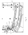
- the invention relates to a door 1, able to close an opening an internal compartment incorporating at least one movable member, in particular a motor, and potentially dangerous, in particular intended to authorize access to a tank of a mixer in order to allow maintenance operations, constituted by an articulated opening 2, in particular by means of hinge or hinge 3 to a frame 4.
- the door 1 is equipped with a safety device 5 with a double locking point 6 1 , 6 2 .
- the safety device 5 is actuated by two control levers 7 1 , 7 2 , each lever being provided with a bolt 8 adapted to engage with a latch 9, in the locking position, or to extract from said striker when rotation of said corresponding lever.
- the safety device further has controlled locking means 10, prohibiting the opening of the door, at least when said movable member is active.
- the opening and closing paths of the two control levers 7 1 , 7 2 overlap, at least partially.
- One of the two levers, said first control lever 7 1 is an obstacle, in the locked position, for the other lever, said second control lever 7 2 , when unlocking the safety device 5.
- the locking means controlled 10 are constituted by a single lock 11 adapted to immobilize said first control lever 7 1 in the locking position.
- Said single lock 11 may be an element of a key transfer locking device according to the European standard EN 1088, relating to the safety of the machines.
- the lock of the door and the switch, in particular on / off of the machine, which also includes a lock share the same transferable key.
- the essential feature of the system is that the key is kept captive either in the lock of the door, or in the lock associated with the switch. The key can only be released when the door is closed and locked. This allows the transfer of the key from the door to the switch.
- Closing the switch will hold the key so that it can not be removed while the switch is in the "on" position.
- the lock 11 is electrically controlled and ensures the locking of the first control lever 7 1 as the motor means of the movable member are under tension.
- first and the second control levers 7 1 , 7 2 are articulated to the opening 2 along two parallel axes of rotation to be able to pivot in the same plane. Strikes 9 of the two locking points 6 1 , 6 2 , are located on either side of the compartment opening, secured to the frame.
- Each control lever 7 1 , 7 2 may have at its distal end a control handle 12.
- the proximal end of the lever is provided with the locking bolt 8.
- the lever has an intermediate hinge 13 located near its proximal end.
- the strikes 9 may each consist of a hook-forming element adapted to receive the bolt 8 of the control lever 7 1 , 7 2 .
- the opening 2 is equipped with a lower control lever 7 1 and a control lever 7 2 upper.
- the two levers are substantially identical, each longer than half the height of the door.
- the strikes are constituted by hook elements.
- the lower control lever 7 1 rotates, in the clockwise direction, to open, to extract the latch 9, the bolt 8.
- the lower control lever 7 1 constitutes an obstacle for the upper control lever 2 , which rotates when opening, counter-clockwise.
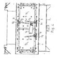
- the lock 11 is carried by a leaf 14, articulated to the frame 4.
- the lock 11 and its wing 14 can be moved from a contact position in which said lock comes to cover the opening 2, when the latter is closed, to a release position allowing the rotation of the opening 2 and thus its opening.
- the flapper assembly 14 / lock 11 is hinged in particular hinge to the frame 4, to cover the free edge of the opening 2, the opposite side of the hinges 3 of the latter.
- the lock 11 may have a latch and means for actuating the latch, allowing either to engage the latch in a reservation of the opening 2 (not shown) and thus the locking of the lock 11 and its flap 14 to the opening 2, in said contact position, or to extract the latch of the reservation for retracting, in rotation, the lock 11 and its flap 14 in said release position.
- the lock 11 or its flap may be provided with an element 15 for securing the first control lever 7 1 to immobilize in rotation said first lever when the lock 11 and the flap 14 are in the so-called contact position with the sash 2 .
- the fastening element 15 may be constituted by a rod secured to the lock assembly 11 / flapper 14.
- the rod has an orifice 16 intended to engage with a lug 17 of the first control lever 7 1 to immobilize its rotational position .
- the invention can be adapted to a double door.
- the double door has a first door 1 1 adapted to come to cover the second door 1 2 in the closed position, blocking the latter.
- the first door 1 1 is equipped with the safety device 5 with double locking point 6 1 , 6 2 with its two control levers 7 1 , 7 2 .
- the first lever 7 1 constitutes an obstacle for the second lever 7 2 during unlocking.
- the safety device has a single lock 11, able to lock the first lever 7 1 , in the locking position.
- the lock 11 is carried by a leaf 14 hinged to the second door 1 2 .
- the double door may have a third locking point with a keeper 9 and a third lever 7 5 of the second holder 1 2.
- the invention will find particular use as a service door to allow access to the tank of a mixer, including fixed bowl, for mixing dry or wet components, especially for the preparation of concrete.
Landscapes
- Engineering & Computer Science (AREA)
- Mechanical Engineering (AREA)
- Structural Engineering (AREA)
- Chemical & Material Sciences (AREA)
- Chemical Kinetics & Catalysis (AREA)
- Lock And Its Accessories (AREA)
- Power-Operated Mechanisms For Wings (AREA)
Claims (10)
- Tür (1), geeignet, um eine Öffnung eines Innenraums, der wenigstens ein bewegliches Organ, nämlich einen Motor, integriert und potentiell gefährlich ist, zu schließen, die nämlich dazu bestimmt ist, den Zugang zu der Mulde eines Kneters zu gestatten, um Wartungsvorgänge zu erlauben, bestehend aus einem nämlich über Scharniere oder Gelenbänder (3) gelenkig an einer Türzarge (4) befestigten Flügel (2), wobei die besagte Tür (1) mit einer Sicherheitsvorrichtung (5) mit doppeltem Verriegelungspunkt (61, 62) versehen ist und mittels zwei Steuerhebel (71, 72) betätigt wird, wobei jeder Hebel (71, 72) mit einem Riegel (8) versehen ist, der geeignet ist, in Verriegelungsposition mit einem Schließblech im Eingriff (9) zu kommen, oder während der Drehung des besagten entsprechenden Hebels aus dem besagten Schließblech herauszukommen, wobei die Sicherheitsvorrichtung (5) außerdem gesteuert Sperrmittel (10) aufweist, die wenigstens dann, wenn das bewegliche Organ aktiv ist, das Öffnen der Tür verhindert, dadurch gekennzeichnet, dass sich die Öffnungs- und Schließungswege der beiden Steuerhebel (71, 72) wenigstens teilweise überlappen, wobei einer der beiden Hebel, der als Steuerhebel (71) bezeichnet wird, in der Verriegelungsposition ein Hindernis für den anderen Hebel, der als zweiter Steuerhebel (72) bezeichnet wird, während der Entriegelung der Sicherheitsvorrichtung (5) bildet, wobei die besagten gesteuerten Sperrmittel (10) aus einem einzigen Schloß (11) besteht, das geeignet ist, den besagten ersten Steuerhebel (71) in Verriegelungsposition zu sperren.
- Tür nach Anspruch 1, bei der das Schloß (11) elektrisch gesteuert wird.
- Tür nach Anspruch 1 oder 2, bei der der erste und der zweite Steuerhebel gemäß zwei parallelen Drehachsen gelenkig an dem Flügel (2) befestigt sind, um in einer selben Ebene schwenken zu können, wobei sich die Schließbleche (9) der zwei Verriegelungspunkte (61, 62) beiderseits der Öffnung des Raumes an der Türzarge (4) befestigt befinden.
- Tür nach Anspruch 3, bei der jeder Steuerhebel (71, 72) an seinem distalen Ende einen Betätigungsgriff (12) aufweist, wobei das proximale Ende des Hebels mit dem Verriegelungsriegel (8) versehen ist, wobei der Hebel ein in der Nähe seines proximalen Endes befindlicher Zwischengelenk (13) aufweist.
- Tür nach einem der Ansprüche 1 bis 4, bei der die Schließbleche (9) jeweils aus einem, einen Haken bildenden Element bestehen, das geeignet ist, den Riegel (8) des Steuerhebels aufzunehmen.
- Tür nach einem der Ansprüche 1 bis 5, bei der das Schloß (11) von einer gelenkig an der Türzarge (4) oder auch an einer weiteren Tür (12) befestigten Klappe (14) getragen wird, wobei das besagte Schloß (11) und seine Klappe von einer Berührungsposition, in der das besagte Schloß den Flügel (2) überdeckt, wenn dieser letztere geschlossen ist, in eine Freigabeposition, die das Drehen des Flügels und also sein Öffnen erlaubt, versetzt werden kann.
- Tür nach Anspruch 6, bei der das Schloß (11) einen Riegel und Riegelbetatigungsmittel aufweist, die es erlauben, entweder den besagten Riegel in eine Aussparung im Flügel (2) eingreifen zu lassen und also die feste Verbindung des Schloßes (11) und seiner Klappe (14) mit dem Flügel (2) in der besagten Berührungsposition zustande zu bringen, oder den Riegel aus der Aussparung-zu ziehen, was es erlaubt, das Schloß (11) und seine Klappe (14) in der besagten Freigabeposition zurückzuziehen.
- Tür nach Anspruch 6 oder 7, bei der das Schloß (11) oder die Klappe (14) mit einem Element (15) zur festen Verbindung des ersten Steuerhebels (71) versehen ist, das den ersten Hebel in Drehung sperrt, wenn sich das Schloß (11) und die besagte Klappe (14) in der sogenannten Berührungsposition mit dem Flügel (2) befinden.
- Tür nach Anspruch 8, bei der das Element (15) zur festen Verbindung aus einer Stange besteht, die an der Ganzheit von Schloß (11) und Klappe (14) befestigt ist, wobei die Stange ein Loch (16) aufweist, das dazu bestimmt ist, mit einem Stift (17) des ersten Steuerhebels (71) im Eingriff zu kommen, um seine Drehlage zu sperren.
- Verwendung einer Tür nach Anspruch 1 als Diensttür, um den Zugang zu der Mulde eines Kneters, nämlich mit fester Mulde, zum Mischen von trocknen oder feuchtigen Bestandteilen zu erlauben, nämlich für die Aufbereitung von Beton.
Applications Claiming Priority (1)
| Application Number | Priority Date | Filing Date | Title |
|---|---|---|---|
| FR0604466A FR2901170B1 (fr) | 2006-05-18 | 2006-05-18 | Porte, apte a fermer une ouverture d'un compartiment interne integrant au moins l'organe mobile notamment moteur, et potentiellement dangereux. |
Publications (2)
| Publication Number | Publication Date |
|---|---|
| EP1857618A1 EP1857618A1 (de) | 2007-11-21 |
| EP1857618B1 true EP1857618B1 (de) | 2010-07-07 |
Family
ID=37726676
Family Applications (1)
| Application Number | Title | Priority Date | Filing Date |
|---|---|---|---|
| EP07370010A Not-in-force EP1857618B1 (de) | 2006-05-18 | 2007-05-10 | Tür, die eine Öffnung eines Innenraums verschließen kann, der mindestens ein bewegliches und potenziell gefährliches Element, insbesondere einen Antrieb, enthält |
Country Status (4)
| Country | Link |
|---|---|
| EP (1) | EP1857618B1 (de) |
| AT (1) | ATE473337T1 (de) |
| DE (1) | DE602007007541D1 (de) |
| FR (1) | FR2901170B1 (de) |
Families Citing this family (4)
| Publication number | Priority date | Publication date | Assignee | Title |
|---|---|---|---|---|
| GB0703584D0 (en) * | 2007-02-23 | 2007-04-04 | Dry Silo Mortars Ltd | Mixing apparatus |
| IT1403829B1 (it) * | 2011-01-27 | 2013-10-31 | Le Officine Riunite Udine S P A | Apparecchiatura con tamburo rotante, quale una autobetoniera |
| CN111775332B (zh) * | 2020-06-04 | 2021-08-17 | 儋州泰达实业有限公司 | 一种混凝土配制用粉料添加装置 |
| CN113478656B (zh) * | 2021-07-01 | 2022-05-27 | 包头市公路工程股份有限公司 | 水稳拌合站单轮动断触头在拌缸清理中保障安全应用施工工法 |
Family Cites Families (6)
| Publication number | Priority date | Publication date | Assignee | Title |
|---|---|---|---|---|
| DE82631C (de) * | ||||
| DE1020895B (de) * | 1956-05-25 | 1957-12-12 | Siegener A G Fuer Eisenkonstru | Vorreiberverschluss fuer gasdichte, druckfeste Tueren |
| FR1417517A (fr) * | 1964-12-07 | 1965-11-12 | Fermeture de sûreté notamment pour volet ouvrant de portière de voiture automobile | |
| DE2752855A1 (de) * | 1977-11-26 | 1979-05-31 | Otto Conrads | Vorrichtung zur einbruchsicherung von fenstern und tueren mit schwenkhebelbetaetigung, insbesondere mit dreh-kipp- oder hebetuerbeschlaegen |
| CN2767105Y (zh) * | 2005-01-28 | 2006-03-29 | 上海斯加科机械有限公司 | 混凝土搅拌机的检修门 |
| CN2767107Y (zh) * | 2005-01-28 | 2006-03-29 | 上海斯加科机械有限公司 | 混凝土搅拌机的行星式电机减速箱 |
-
2006
- 2006-05-18 FR FR0604466A patent/FR2901170B1/fr not_active Expired - Fee Related
-
2007
- 2007-05-10 AT AT07370010T patent/ATE473337T1/de not_active IP Right Cessation
- 2007-05-10 DE DE602007007541T patent/DE602007007541D1/de active Active
- 2007-05-10 EP EP07370010A patent/EP1857618B1/de not_active Not-in-force
Also Published As
| Publication number | Publication date |
|---|---|
| EP1857618A1 (de) | 2007-11-21 |
| FR2901170A1 (fr) | 2007-11-23 |
| ATE473337T1 (de) | 2010-07-15 |
| FR2901170B1 (fr) | 2008-07-18 |
| DE602007007541D1 (de) | 2010-08-19 |
Similar Documents
| Publication | Publication Date | Title |
|---|---|---|
| US10358848B2 (en) | Motor vehicle door lock | |
| US7125057B2 (en) | Lock mechanism | |
| EP0903457B1 (de) | Elektrisches Schloss für Kraftfahrzeugtür | |
| KR102165338B1 (ko) | 플랩 또는 도어용 록 | |
| FR2789717A1 (fr) | Serrure en trois parties, pour ouvrant de vehicule automobile | |
| EP1030012B1 (de) | Kraftfahrzeugschloss mit energiespeichernder Entriegelungsvorrichtung | |
| EP1857618A1 (de) | Tür, die eine Öffnung eines Innenraums verschließen kann, der mindestens ein bewegliches und potenziell gefährliches Element, insbesondere einen Antrieb, enthält | |
| US7182392B2 (en) | Latch device for vehicle access panel door | |
| KR101985554B1 (ko) | 플랩 또는 도어를 위한 록킹 장치 | |
| BE1005314A3 (fr) | Serrure a pene dormant a verrouillage automatique selectif. | |
| EP1030017A1 (de) | Treibstangenschloss enthaltend einen Hakenriegel mit Mitteln zur Riegelblockierung | |
| FR2786521A1 (fr) | Serrure pour portiere droite ou gauche de vehicule automobile | |
| EP2045420A1 (de) | Griffsystem, insbesondere Treibstange, das zur Befestigung auf der Außenseite einer Tür bestimmt ist, wie etwa der Tür eines Kühllasters | |
| FR2467947A1 (fr) | Dispositif de condamnation et de commande d'ouverture d'une porte de vehicule | |
| US5040386A (en) | Antipanic lock with a safety-drum | |
| EP1201854B1 (de) | Treibstangenverschluss, insbesondere für Lastkraftwagen-, Anhänger- oder Behältertüren oder dergleichen | |
| KR100767969B1 (ko) | 테일 게이트 또는 트렁크에 설치되는 래치구조 | |
| FR2866384A1 (fr) | Cremone, destinee a la manoeuvre d'ouverture et de fermeture d'un ouvrant | |
| EP0230808B1 (de) | Verriegelungsvorrichtung für Kraftfahrzeugtürschloss | |
| FR2789718A1 (fr) | Serrure a condamnation enfant, pour ouvrant de vehicule automobile | |
| JP3149367B2 (ja) | ハッチ付車両バックドアのラッチ装置 | |
| JPH0625584Y2 (ja) | 車両のバックドアロック装置 | |
| FR2786527A1 (fr) | Dispositif de relevage pour chassis ouvrant de porte, fenetre ou analogue | |
| JP5802771B2 (ja) | 貨物自動車の荷箱扉開閉用操作ハンドルの掛金装置 | |
| EP1862619A1 (de) | Türeinheit für Fahrzeuge, wie insbesondere für Lastkraftwagen |
Legal Events
| Date | Code | Title | Description |
|---|---|---|---|
| PUAI | Public reference made under article 153(3) epc to a published international application that has entered the european phase |
Free format text: ORIGINAL CODE: 0009012 |
|
| AK | Designated contracting states |
Kind code of ref document: A1 Designated state(s): AT BE BG CH CY CZ DE DK EE ES FI FR GB GR HU IE IS IT LI LT LU LV MC MT NL PL PT RO SE SI SK TR |
|
| AX | Request for extension of the european patent |
Extension state: AL BA HR MK YU |
|
| 17P | Request for examination filed |
Effective date: 20080515 |
|
| AKX | Designation fees paid |
Designated state(s): AT BE BG CH CY CZ DE DK EE ES FI FR GB GR HU IE IS IT LI LT LU LV MC MT NL PL PT RO SE SI SK TR |
|
| GRAP | Despatch of communication of intention to grant a patent |
Free format text: ORIGINAL CODE: EPIDOSNIGR1 |
|
| GRAS | Grant fee paid |
Free format text: ORIGINAL CODE: EPIDOSNIGR3 |
|
| GRAA | (expected) grant |
Free format text: ORIGINAL CODE: 0009210 |
|
| AK | Designated contracting states |
Kind code of ref document: B1 Designated state(s): AT BE BG CH CY CZ DE DK EE ES FI FR GB GR HU IE IS IT LI LT LU LV MC MT NL PL PT RO SE SI SK TR |
|
| REG | Reference to a national code |
Ref country code: GB Ref legal event code: FG4D Free format text: NOT ENGLISH |
|
| REG | Reference to a national code |
Ref country code: CH Ref legal event code: EP |
|
| REG | Reference to a national code |
Ref country code: IE Ref legal event code: FG4D |
|
| REF | Corresponds to: |
Ref document number: 602007007541 Country of ref document: DE Date of ref document: 20100819 Kind code of ref document: P |
|
| RAP2 | Party data changed (patent owner data changed or rights of a patent transferred) |
Owner name: COUVROT |
|
| REG | Reference to a national code |
Ref country code: NL Ref legal event code: VDEP Effective date: 20100707 |
|
| PG25 | Lapsed in a contracting state [announced via postgrant information from national office to epo] |
Ref country code: SI Free format text: LAPSE BECAUSE OF FAILURE TO SUBMIT A TRANSLATION OF THE DESCRIPTION OR TO PAY THE FEE WITHIN THE PRESCRIBED TIME-LIMIT Effective date: 20100707 |
|
| LTIE | Lt: invalidation of european patent or patent extension |
Effective date: 20100707 |
|
| PG25 | Lapsed in a contracting state [announced via postgrant information from national office to epo] |
Ref country code: LT Free format text: LAPSE BECAUSE OF FAILURE TO SUBMIT A TRANSLATION OF THE DESCRIPTION OR TO PAY THE FEE WITHIN THE PRESCRIBED TIME-LIMIT Effective date: 20100707 Ref country code: FI Free format text: LAPSE BECAUSE OF FAILURE TO SUBMIT A TRANSLATION OF THE DESCRIPTION OR TO PAY THE FEE WITHIN THE PRESCRIBED TIME-LIMIT Effective date: 20100707 Ref country code: AT Free format text: LAPSE BECAUSE OF FAILURE TO SUBMIT A TRANSLATION OF THE DESCRIPTION OR TO PAY THE FEE WITHIN THE PRESCRIBED TIME-LIMIT Effective date: 20100707 Ref country code: NL Free format text: LAPSE BECAUSE OF FAILURE TO SUBMIT A TRANSLATION OF THE DESCRIPTION OR TO PAY THE FEE WITHIN THE PRESCRIBED TIME-LIMIT Effective date: 20100707 |
|
| REG | Reference to a national code |
Ref country code: IE Ref legal event code: FD4D |
|
| PG25 | Lapsed in a contracting state [announced via postgrant information from national office to epo] |
Ref country code: PL Free format text: LAPSE BECAUSE OF FAILURE TO SUBMIT A TRANSLATION OF THE DESCRIPTION OR TO PAY THE FEE WITHIN THE PRESCRIBED TIME-LIMIT Effective date: 20100707 Ref country code: PT Free format text: LAPSE BECAUSE OF FAILURE TO SUBMIT A TRANSLATION OF THE DESCRIPTION OR TO PAY THE FEE WITHIN THE PRESCRIBED TIME-LIMIT Effective date: 20101108 Ref country code: BG Free format text: LAPSE BECAUSE OF FAILURE TO SUBMIT A TRANSLATION OF THE DESCRIPTION OR TO PAY THE FEE WITHIN THE PRESCRIBED TIME-LIMIT Effective date: 20101007 Ref country code: CY Free format text: LAPSE BECAUSE OF FAILURE TO SUBMIT A TRANSLATION OF THE DESCRIPTION OR TO PAY THE FEE WITHIN THE PRESCRIBED TIME-LIMIT Effective date: 20100707 Ref country code: IS Free format text: LAPSE BECAUSE OF FAILURE TO SUBMIT A TRANSLATION OF THE DESCRIPTION OR TO PAY THE FEE WITHIN THE PRESCRIBED TIME-LIMIT Effective date: 20101107 |
|
| PG25 | Lapsed in a contracting state [announced via postgrant information from national office to epo] |
Ref country code: SE Free format text: LAPSE BECAUSE OF FAILURE TO SUBMIT A TRANSLATION OF THE DESCRIPTION OR TO PAY THE FEE WITHIN THE PRESCRIBED TIME-LIMIT Effective date: 20100707 Ref country code: GR Free format text: LAPSE BECAUSE OF FAILURE TO SUBMIT A TRANSLATION OF THE DESCRIPTION OR TO PAY THE FEE WITHIN THE PRESCRIBED TIME-LIMIT Effective date: 20101008 Ref country code: LV Free format text: LAPSE BECAUSE OF FAILURE TO SUBMIT A TRANSLATION OF THE DESCRIPTION OR TO PAY THE FEE WITHIN THE PRESCRIBED TIME-LIMIT Effective date: 20100707 |
|
| PG25 | Lapsed in a contracting state [announced via postgrant information from national office to epo] |
Ref country code: DK Free format text: LAPSE BECAUSE OF FAILURE TO SUBMIT A TRANSLATION OF THE DESCRIPTION OR TO PAY THE FEE WITHIN THE PRESCRIBED TIME-LIMIT Effective date: 20100707 Ref country code: IE Free format text: LAPSE BECAUSE OF FAILURE TO SUBMIT A TRANSLATION OF THE DESCRIPTION OR TO PAY THE FEE WITHIN THE PRESCRIBED TIME-LIMIT Effective date: 20100707 |
|
| PLBE | No opposition filed within time limit |
Free format text: ORIGINAL CODE: 0009261 |
|
| STAA | Information on the status of an ep patent application or granted ep patent |
Free format text: STATUS: NO OPPOSITION FILED WITHIN TIME LIMIT |
|
| PG25 | Lapsed in a contracting state [announced via postgrant information from national office to epo] |
Ref country code: SK Free format text: LAPSE BECAUSE OF FAILURE TO SUBMIT A TRANSLATION OF THE DESCRIPTION OR TO PAY THE FEE WITHIN THE PRESCRIBED TIME-LIMIT Effective date: 20100707 Ref country code: IT Free format text: LAPSE BECAUSE OF FAILURE TO SUBMIT A TRANSLATION OF THE DESCRIPTION OR TO PAY THE FEE WITHIN THE PRESCRIBED TIME-LIMIT Effective date: 20100707 Ref country code: CZ Free format text: LAPSE BECAUSE OF FAILURE TO SUBMIT A TRANSLATION OF THE DESCRIPTION OR TO PAY THE FEE WITHIN THE PRESCRIBED TIME-LIMIT Effective date: 20100707 Ref country code: RO Free format text: LAPSE BECAUSE OF FAILURE TO SUBMIT A TRANSLATION OF THE DESCRIPTION OR TO PAY THE FEE WITHIN THE PRESCRIBED TIME-LIMIT Effective date: 20100707 Ref country code: EE Free format text: LAPSE BECAUSE OF FAILURE TO SUBMIT A TRANSLATION OF THE DESCRIPTION OR TO PAY THE FEE WITHIN THE PRESCRIBED TIME-LIMIT Effective date: 20100707 |
|
| 26N | No opposition filed |
Effective date: 20110408 |
|
| PG25 | Lapsed in a contracting state [announced via postgrant information from national office to epo] |
Ref country code: ES Free format text: LAPSE BECAUSE OF FAILURE TO SUBMIT A TRANSLATION OF THE DESCRIPTION OR TO PAY THE FEE WITHIN THE PRESCRIBED TIME-LIMIT Effective date: 20101018 |
|
| REG | Reference to a national code |
Ref country code: DE Ref legal event code: R097 Ref document number: 602007007541 Country of ref document: DE Effective date: 20110408 |
|
| PGFP | Annual fee paid to national office [announced via postgrant information from national office to epo] |
Ref country code: FR Payment date: 20110616 Year of fee payment: 5 |
|
| PGFP | Annual fee paid to national office [announced via postgrant information from national office to epo] |
Ref country code: DE Payment date: 20110505 Year of fee payment: 5 |
|
| BERE | Be: lapsed |
Owner name: COUVROT Effective date: 20110531 |
|
| PG25 | Lapsed in a contracting state [announced via postgrant information from national office to epo] |
Ref country code: MT Free format text: LAPSE BECAUSE OF FAILURE TO SUBMIT A TRANSLATION OF THE DESCRIPTION OR TO PAY THE FEE WITHIN THE PRESCRIBED TIME-LIMIT Effective date: 20100707 Ref country code: MC Free format text: LAPSE BECAUSE OF NON-PAYMENT OF DUE FEES Effective date: 20110531 |
|
| REG | Reference to a national code |
Ref country code: CH Ref legal event code: PL |
|
| GBPC | Gb: european patent ceased through non-payment of renewal fee |
Effective date: 20110510 |
|
| PG25 | Lapsed in a contracting state [announced via postgrant information from national office to epo] |
Ref country code: CH Free format text: LAPSE BECAUSE OF NON-PAYMENT OF DUE FEES Effective date: 20110531 Ref country code: LI Free format text: LAPSE BECAUSE OF NON-PAYMENT OF DUE FEES Effective date: 20110531 |
|
| PG25 | Lapsed in a contracting state [announced via postgrant information from national office to epo] |
Ref country code: BE Free format text: LAPSE BECAUSE OF NON-PAYMENT OF DUE FEES Effective date: 20110531 |
|
| PG25 | Lapsed in a contracting state [announced via postgrant information from national office to epo] |
Ref country code: GB Free format text: LAPSE BECAUSE OF NON-PAYMENT OF DUE FEES Effective date: 20110510 |
|
| REG | Reference to a national code |
Ref country code: FR Ref legal event code: ST Effective date: 20130131 |
|
| REG | Reference to a national code |
Ref country code: DE Ref legal event code: R119 Ref document number: 602007007541 Country of ref document: DE Effective date: 20121201 |
|
| PG25 | Lapsed in a contracting state [announced via postgrant information from national office to epo] |
Ref country code: FR Free format text: LAPSE BECAUSE OF NON-PAYMENT OF DUE FEES Effective date: 20120531 |
|
| PG25 | Lapsed in a contracting state [announced via postgrant information from national office to epo] |
Ref country code: LU Free format text: LAPSE BECAUSE OF NON-PAYMENT OF DUE FEES Effective date: 20110510 |
|
| PG25 | Lapsed in a contracting state [announced via postgrant information from national office to epo] |
Ref country code: DE Free format text: LAPSE BECAUSE OF NON-PAYMENT OF DUE FEES Effective date: 20121201 |
|
| PG25 | Lapsed in a contracting state [announced via postgrant information from national office to epo] |
Ref country code: TR Free format text: LAPSE BECAUSE OF FAILURE TO SUBMIT A TRANSLATION OF THE DESCRIPTION OR TO PAY THE FEE WITHIN THE PRESCRIBED TIME-LIMIT Effective date: 20100707 |
|
| PG25 | Lapsed in a contracting state [announced via postgrant information from national office to epo] |
Ref country code: HU Free format text: LAPSE BECAUSE OF FAILURE TO SUBMIT A TRANSLATION OF THE DESCRIPTION OR TO PAY THE FEE WITHIN THE PRESCRIBED TIME-LIMIT Effective date: 20100707 |