EP1857718A2 - Dynamische Gleitringdichtung - Google Patents
Dynamische Gleitringdichtung Download PDFInfo
- Publication number
- EP1857718A2 EP1857718A2 EP07107310A EP07107310A EP1857718A2 EP 1857718 A2 EP1857718 A2 EP 1857718A2 EP 07107310 A EP07107310 A EP 07107310A EP 07107310 A EP07107310 A EP 07107310A EP 1857718 A2 EP1857718 A2 EP 1857718A2
- Authority
- EP
- European Patent Office
- Prior art keywords
- annular
- sealing element
- mechanical seal
- flange
- annular sealing
- Prior art date
- Legal status (The legal status is an assumption and is not a legal conclusion. Google has not performed a legal analysis and makes no representation as to the accuracy of the status listed.)
- Withdrawn
Links
- 238000007789 sealing Methods 0.000 claims abstract description 75
- 239000012530 fluid Substances 0.000 claims abstract description 10
- 230000003068 static effect Effects 0.000 claims abstract description 9
- 230000008878 coupling Effects 0.000 claims description 8
- 238000010168 coupling process Methods 0.000 claims description 8
- 238000005859 coupling reaction Methods 0.000 claims description 8
- 238000005516 engineering process Methods 0.000 description 2
- 230000000670 limiting effect Effects 0.000 description 2
- 229910000831 Steel Inorganic materials 0.000 description 1
- 238000009825 accumulation Methods 0.000 description 1
- 239000000463 material Substances 0.000 description 1
- 230000001404 mediated effect Effects 0.000 description 1
- 238000012856 packing Methods 0.000 description 1
- 230000000149 penetrating effect Effects 0.000 description 1
- 239000000843 powder Substances 0.000 description 1
- 239000010959 steel Substances 0.000 description 1
Images


Classifications
-
- F—MECHANICAL ENGINEERING; LIGHTING; HEATING; WEAPONS; BLASTING
- F16—ENGINEERING ELEMENTS AND UNITS; GENERAL MEASURES FOR PRODUCING AND MAINTAINING EFFECTIVE FUNCTIONING OF MACHINES OR INSTALLATIONS; THERMAL INSULATION IN GENERAL
- F16J—PISTONS; CYLINDERS; SEALINGS
- F16J15/00—Sealings
- F16J15/16—Sealings between relatively-moving surfaces
- F16J15/34—Sealings between relatively-moving surfaces with slip-ring pressed against a more or less radial face on one member
- F16J15/3464—Mounting of the seal
- F16J15/348—Pre-assembled seals, e.g. cartridge seals
Definitions
- the present invention relates to a dynamic mechanical seal.
- Such bush is rigidly coupled to the shaft by means of an external annular element, which is fixed to the shaft and to the bush on the opposite side of the second annular sealing element, which rotates with respect to the flange, i.e., outside the body of the machine with which the mechanical seal is associated.
- the external annular element is fixed temporarily to the flange during the fitting of the seal to the machine body and is rigidly fixed to the shaft and to the bush by means of a plurality of grub screws which are screwed in a radial direction so as to engage the interior of respective radial threaded holes in the outer annular element, so as to push against the shaft.
- the bush is the component that holds the seal together by means of the flange, being shaped by the part that lies inside the stuffing box in order to contain the rotating sealing annular element, and at the opposite end, which is external to the flange, in order to be fixed to the outer annular body.
- Said bush is in itself a very expensive element, since it is a steel monobloc, and entails a certain radial and axial space occupation.
- the bush is shaped so that the annular rotating sealing element is inserted in its seat on the bush by interposing a first O-ring.
- the static sealing annular element is pressed against the rotating sealing annular element by a plurality of springs, which are arranged so as to push between the flange and the static sealing annular element; said static sealing element is therefore free to perform small movements in an axial direction, and a second O-ring is interposed between it and the flange and also protects the springs against the fluid and dirt that arrives from the stuffing box.
- the shape of the bush, of the annular sealing elements and of the respective seats do not prevent the dirt carried by the fluid inside the stuffing box from accumulating in the interstices between the annular sealing elements and the respective seats, and against the O-rings; this event severely compromises the efficiency of the mechanical seal and limits the ability of the seal to adapt to vibrations both in a radial direction and an axial direction of the shaft, since these interstices and the contact mediated only by the O-rings between the annular sealing elements and their seats is indeed what allows a certain degree of adaptability of the seal to the vibrations of the rotating shaft.
- the aim of the present invention is to provide a mechanical seal which solves the drawbacks of known mechanical seals.
- an object of the present invention is to provide a mechanical seal which is more compact both axially and radially and is simpler to provide even on stuffing boxes which are in use and are not appropriately shaped complementarily.
- Another object of the present invention is to provide a mechanical seal which is capable of keeping unchanged the qualities of adaptability to radial and axial vibrations of the shaft.
- Another object of the present invention is to provide a mechanical seal whose efficiency, effectiveness and duration are not lower than those of known types of seal.
- Another object of the present invention is to provide a mechanical seal which is structurally more simple, can be manufactured at lower costs with respect to known seals and can also be produced cheaply with known systems and technologies.
- a dynamic mechanical seal characterized in that it comprises two annular sealing elements which are pressed against each other and are in contact by means of two corresponding faces, a first static annular sealing element, which forms a stationary face and is directed toward a stuffing box of the body of the machine with which the mechanical seal is associated, said first annular element being rigidly coupled to a supporting flange, and a second rotating annular sealing element, which forms a rotating sealing face, which is rigidly coupled to an external annular element, which in turn is fixed to the rotating shaft and is arranged externally and adjacent to the flange and to the body of the machine with which the mechanical seal is associated, said first annular sealing element having an internal annular surface, which faces the rotating shaft, which is substantially frustum-shaped, with a radius which is greater on the side of the stuffing box and a radius which is smaller proximate to the second adjacent annular sealing element, said frustum-shaped surface being adapted to form
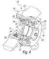
- a mechanical seal according to the invention is generally designated by the reference numeral 10.
- the seal 10 comprises two annular sealing elements 11 and 12, which are pressed against each other and are in contact by means of two corresponding faces 13 and 14.
- the first annular sealing element 11 has an internal annular surface 18 which faces the rotating shaft 17 and is substantially frustum-shaped, with a larger radius on the side of the stuffing box and a smaller radius proximate to the second adjacent annular sealing element 12.
- the frustum-shaped surface 18 forms a region for the recirculation of fluid inside the stuffing box away from the two annular sealing elements 11 and 12, providing in practice the theory known generally as "conical stuffing box", according to which if the stuffing box, i.e., the seat typically intended for a packing, is frustum-shaped, the recirculation of fluid tends to move dirt away from the seal.
- the conical apex angle of the internal surface 18 is approximately 9°.
- the first annular sealing element 11 is arranged within the flange 15 and has a smaller axial space occupation than the flange 15.
- the first annular sealing element 11 is constituted by a central body 19 which has a frustum-shaped internal surface 18, by a ring 20 for coupling to the flange 15, and by a terminal annular portion 21, the end of which defines the stationary sealing face 13.
- the first sealing element 11 is rigidly coupled to the flange by means of rotation-preventing blocks 22, which are inserted in corresponding holes 23 provided in an internal shoulder 24 of the flange 15, which faces the coupling ring 20, and in corresponding forks 25 provided on the coupling ring 20.
- Springs 26 for pushing the first sealing element 11 against the second sealing element 12 are interposed between the ring 20 and the shoulder 24.
- the outer surface 27 of the central body 19 of the first annular sealing element 11 is in contact with the internal surface 28 of the flange 15 by interposing a first O-ring 29 or other equivalent sealing means.
- the second rotating annular sealing element 12 has a substantially rectangular cross-section, with an annular slot 30, provided on the face that lies opposite the rotating sealing face 14, for accommodating a second O-ring 31 or other equivalent sealing means adapted to support the second sealing element 12 on a corresponding collar 32 which protrudes axially from the outer annular element 16 toward the inside of the flange 15.
- the collar 32 is indeed surrounded with clearance by the second annular sealing element 12.
- the two O-rings 29 and 31, the springs 26 and the forks 25 in which the blocks 22 are free to move in a radial direction allow the annular sealing elements 11 and 12 a certain freedom to move with respect to each other while keeping the sealing faces 13 and 14 in mutual contact, in addition to the possibility for both to follow axial and radial vibrations of the rotating shaft 17 and radial misalignments thereof.
- the conical surface 18 and the recirculation region formed thereby prevent the dirt of the fluid of the stuffing box to penetrate to the sealing faces 13 and 14, slowing the accumulation of debris and dirt and slowing the wear of the coupling, ultimately improving the performance and life of the mechanical seal 10 according to the invention.
- the outer annular element 16 is rigidly coupled to the shaft 17 by means of threaded elements 33, for example grub screws, which are screwed radially through the outer annular element 16 until they press against the surface 34 of the shaft 17.
- the outer annular element 16 locks the second rotating annular sealing element 12 against the first annular sealing element 11, which is static and rigidly coupled to the flange 15.
- the inner cylindrical surface 35 of the outer annular element 16 has an annular slot 36 for a corresponding O-ring 37 or other equivalent sealing means adapted to be pressed against the outer surface 34 of the shaft 17 so as to apply a static seal which prevents the fluid of the stuffing box to exit, penetrating in the clearance between the shaft 17 and the outer annular element 16.
- the mechanical seal 10 according to the invention does not have an element such as the bush of the known seal cited above.
- the figures also show the means for locking the outer annular element 16 during the fitting of the seal 10.
- Jaws 36 which are fixed in opposition in pairs and are fixed to the outer annular element 16 by way of screws 17 are shown by way of example.
- the present invention provides a mechanical seal which is more compact both axially and radially and is easier to provide even on stuffing boxes which are in use and are not appropriately shaped complementarily.
- the present invention provides a mechanical seal which is capable of keeping unchanged the qualities of adaptability to radial and axial vibrations of the shaft by way of the particular protection of the annular sealing elements determined by the frustum-shaped internal surface of the first annular sealing element.
- the present invention provides a mechanical seal whose efficiency, effectiveness and duration are not lower than those of known types of seal.
- the present invention provides a mechanical seal which is structurally simpler, can be manufactured with lower costs than known seals, and can be provided cheaply with known systems and technologies.
- the materials employed may be any according to requirements and to the state of the art.
Landscapes
- Engineering & Computer Science (AREA)
- General Engineering & Computer Science (AREA)
- Mechanical Engineering (AREA)
- Mechanical Sealing (AREA)
Applications Claiming Priority (1)
| Application Number | Priority Date | Filing Date | Title |
|---|---|---|---|
| ITPD20060192 ITPD20060192A1 (it) | 2006-05-15 | 2006-05-15 | Tenuta meccanica di tipo dinamico perfezionata |
Publications (2)
| Publication Number | Publication Date |
|---|---|
| EP1857718A2 true EP1857718A2 (de) | 2007-11-21 |
| EP1857718A3 EP1857718A3 (de) | 2008-07-23 |
Family
ID=38359839
Family Applications (1)
| Application Number | Title | Priority Date | Filing Date |
|---|---|---|---|
| EP07107310A Withdrawn EP1857718A3 (de) | 2006-05-15 | 2007-05-02 | Dynamische Gleitringdichtung |
Country Status (2)
| Country | Link |
|---|---|
| EP (1) | EP1857718A3 (de) |
| IT (1) | ITPD20060192A1 (de) |
Citations (1)
| Publication number | Priority date | Publication date | Assignee | Title |
|---|---|---|---|---|
| EP1288541A2 (de) | 2001-08-31 | 2003-03-05 | EAGLE INDUSTRY Co., Ltd. | Gleitringdichtung |
Family Cites Families (2)
| Publication number | Priority date | Publication date | Assignee | Title |
|---|---|---|---|---|
| GB8806242D0 (en) * | 1988-03-16 | 1988-04-13 | Ibex Eng Co Ltd | Improved lobe pump |
| US5938205A (en) * | 1997-08-18 | 1999-08-17 | A.W. Chesterton Company | Method and apparatus for optimizing barrier fluid flow for promoting cool running of a cartridge dual seal |
-
2006
- 2006-05-15 IT ITPD20060192 patent/ITPD20060192A1/it unknown
-
2007
- 2007-05-02 EP EP07107310A patent/EP1857718A3/de not_active Withdrawn
Patent Citations (1)
| Publication number | Priority date | Publication date | Assignee | Title |
|---|---|---|---|---|
| EP1288541A2 (de) | 2001-08-31 | 2003-03-05 | EAGLE INDUSTRY Co., Ltd. | Gleitringdichtung |
Also Published As
| Publication number | Publication date |
|---|---|
| ITPD20060192A1 (it) | 2007-11-16 |
| EP1857718A3 (de) | 2008-07-23 |
Similar Documents
| Publication | Publication Date | Title |
|---|---|---|
| EP2287499B1 (de) | Dichtungsanordnung | |
| JP5222408B2 (ja) | シールアセンブリの製造方法 | |
| EP2430338B1 (de) | Gleitringdichtungsanordnung | |
| KR20140129216A (ko) | 밀봉장치 및 그의 제조방법 | |
| JP6941479B2 (ja) | シール構造及びメカニカルシール | |
| EP1152176A2 (de) | Wellendichtung | |
| AU2015331688B2 (en) | Sealing device | |
| AU2015270310B2 (en) | High-pressure rotary seal-plug assembly with expandable continuous ring | |
| EP1948983B1 (de) | Elastomere mechanische federdichtung | |
| CA3110590C (en) | Sealing ring and use thereof | |
| US11131387B2 (en) | Sealing ring and seal arrangement comprising such a sealing ring | |
| EP1857718A2 (de) | Dynamische Gleitringdichtung | |
| US8256697B2 (en) | Seal assembly with shroud | |
| KR102480370B1 (ko) | 밀봉 장치 및 밀봉 어셈블리 | |
| WO2020112558A1 (en) | Seal assembly with anti-rotation and stability features | |
| EP3857101B1 (de) | Mechanische dichtung mit integriertem rfid-sensor | |
| EP4206499B1 (de) | Dichtungsvorrichtung | |
| EP1224414A1 (de) | Gleitringdichtung | |
| US20050150375A1 (en) | Hydraulic rotory actuator with sealing ring | |
| WO2016013029A2 (en) | Seal protection assembly | |
| CN105201717A (zh) | 用于燃料喷射系统的燃料高压泵 | |
| WO2008131464A1 (en) | A seal | |
| WO2010101948A1 (en) | Iris labyrinth seal assembly | |
| AU4268100A (en) | Mechanical shaft to housing seal | |
| GB2410774A (en) | A rotary shaft seal including a seal element with energising means |
Legal Events
| Date | Code | Title | Description |
|---|---|---|---|
| PUAI | Public reference made under article 153(3) epc to a published international application that has entered the european phase |
Free format text: ORIGINAL CODE: 0009012 |
|
| AK | Designated contracting states |
Kind code of ref document: A2 Designated state(s): AT BE BG CH CY CZ DE DK EE ES FI FR GB GR HU IE IS IT LI LT LU LV MC MT NL PL PT RO SE SI SK TR |
|
| AX | Request for extension of the european patent |
Extension state: AL BA HR MK YU |
|
| PUAL | Search report despatched |
Free format text: ORIGINAL CODE: 0009013 |
|
| AK | Designated contracting states |
Kind code of ref document: A3 Designated state(s): AT BE BG CH CY CZ DE DK EE ES FI FR GB GR HU IE IS IT LI LT LU LV MC MT NL PL PT RO SE SI SK TR |
|
| AX | Request for extension of the european patent |
Extension state: AL BA HR MK RS |
|
| 17P | Request for examination filed |
Effective date: 20090116 |
|
| AKX | Designation fees paid |
Designated state(s): AT BE BG CH CY CZ DE DK EE ES FI FR GB GR HU IE IS IT LI LT LU LV MC MT NL PL PT RO SE SI SK TR |
|
| 17Q | First examination report despatched |
Effective date: 20100224 |
|
| STAA | Information on the status of an ep patent application or granted ep patent |
Free format text: STATUS: THE APPLICATION IS DEEMED TO BE WITHDRAWN |
|
| 18D | Application deemed to be withdrawn |
Effective date: 20100907 |