EP1857764A2 - Dispositif de transmission de la chaleur et procédé destiné à la fabrication d'un dispositif de transmission de la chaleur - Google Patents
Dispositif de transmission de la chaleur et procédé destiné à la fabrication d'un dispositif de transmission de la chaleur Download PDFInfo
- Publication number
- EP1857764A2 EP1857764A2 EP07107709A EP07107709A EP1857764A2 EP 1857764 A2 EP1857764 A2 EP 1857764A2 EP 07107709 A EP07107709 A EP 07107709A EP 07107709 A EP07107709 A EP 07107709A EP 1857764 A2 EP1857764 A2 EP 1857764A2
- Authority
- EP
- European Patent Office
- Prior art keywords
- heat transfer
- transfer device
- pore structure
- porosity
- base body
- Prior art date
- Legal status (The legal status is an assumption and is not a legal conclusion. Google has not performed a legal analysis and makes no representation as to the accuracy of the status listed.)
- Withdrawn
Links
Images


Classifications
-
- F—MECHANICAL ENGINEERING; LIGHTING; HEATING; WEAPONS; BLASTING
- F28—HEAT EXCHANGE IN GENERAL
- F28F—DETAILS OF HEAT-EXCHANGE AND HEAT-TRANSFER APPARATUS, OF GENERAL APPLICATION
- F28F13/00—Arrangements for modifying heat-transfer, e.g. increasing, decreasing
- F28F13/18—Arrangements for modifying heat-transfer, e.g. increasing, decreasing by applying coatings, e.g. radiation-absorbing, radiation-reflecting; by surface treatment, e.g. polishing
- F28F13/185—Heat-exchange surfaces provided with microstructures or with porous coatings
- F28F13/187—Heat-exchange surfaces provided with microstructures or with porous coatings especially adapted for evaporator surfaces or condenser surfaces, e.g. with nucleation sites
-
- C—CHEMISTRY; METALLURGY
- C23—COATING METALLIC MATERIAL; COATING MATERIAL WITH METALLIC MATERIAL; CHEMICAL SURFACE TREATMENT; DIFFUSION TREATMENT OF METALLIC MATERIAL; COATING BY VACUUM EVAPORATION, BY SPUTTERING, BY ION IMPLANTATION OR BY CHEMICAL VAPOUR DEPOSITION, IN GENERAL; INHIBITING CORROSION OF METALLIC MATERIAL OR INCRUSTATION IN GENERAL
- C23C—COATING METALLIC MATERIAL; COATING MATERIAL WITH METALLIC MATERIAL; SURFACE TREATMENT OF METALLIC MATERIAL BY DIFFUSION INTO THE SURFACE, BY CHEMICAL CONVERSION OR SUBSTITUTION; COATING BY VACUUM EVAPORATION, BY SPUTTERING, BY ION IMPLANTATION OR BY CHEMICAL VAPOUR DEPOSITION, IN GENERAL
- C23C4/00—Coating by spraying the coating material in the molten state, e.g. by flame, plasma or electric discharge
- C23C4/04—Coating by spraying the coating material in the molten state, e.g. by flame, plasma or electric discharge characterised by the coating material
-
- C—CHEMISTRY; METALLURGY
- C23—COATING METALLIC MATERIAL; COATING MATERIAL WITH METALLIC MATERIAL; CHEMICAL SURFACE TREATMENT; DIFFUSION TREATMENT OF METALLIC MATERIAL; COATING BY VACUUM EVAPORATION, BY SPUTTERING, BY ION IMPLANTATION OR BY CHEMICAL VAPOUR DEPOSITION, IN GENERAL; INHIBITING CORROSION OF METALLIC MATERIAL OR INCRUSTATION IN GENERAL
- C23C—COATING METALLIC MATERIAL; COATING MATERIAL WITH METALLIC MATERIAL; SURFACE TREATMENT OF METALLIC MATERIAL BY DIFFUSION INTO THE SURFACE, BY CHEMICAL CONVERSION OR SUBSTITUTION; COATING BY VACUUM EVAPORATION, BY SPUTTERING, BY ION IMPLANTATION OR BY CHEMICAL VAPOUR DEPOSITION, IN GENERAL
- C23C4/00—Coating by spraying the coating material in the molten state, e.g. by flame, plasma or electric discharge
- C23C4/12—Coating by spraying the coating material in the molten state, e.g. by flame, plasma or electric discharge characterised by the method of spraying
- C23C4/134—Plasma spraying
Definitions
- the invention relates to a heat transfer device, comprising at least one heat transfer surface element with a base body, a first side, on which a first fluid for heat absorption is Louis Mountainbar, and a second side, which is heatable, wherein on the base body on the first side, a pore structure is arranged.
- the invention further relates to a method for producing a heat transfer device, which has at least one heat transfer surface element with a pore structure, wherein the pore structure is arranged on a base body.
- From the DE 101 22 574 A1 is a component for mass and heat transport with a base body and with a material and heat transport supporting layer on at least one component surface known, wherein the coating is produced by a vacuum plasma spraying process. Powder particles are superficially melted to create a pore structure. By the degree of melting is the proportion of open and closed pores set.
- the DE 40 36 932 A1 discloses a method for producing a heat transfer surface in which a mixture of particles of a metal powder and a polymethyl methacrylate powder is flame-sprayed onto a metallic substrate.
- the particles of the polymethylmethacrylate powder form small spaces between particles of the metal powder.
- the prepared coating is heated to remove the particles of polymethyl methacrylate powder from the coating and to form voids at locations previously occupied by these particles.
- a component for a heat exchanger which comprises a porous coating, the pores being produced by removal of a volatile material.
- Heat transfer devices are also known from the publications Asano, H., Shufer, D., Bouyer, E., Müller-Steinhagen, H., Henne, R., 2003, "Improved Heat Transfer by RF Plasma Produced Structured Surfaces", International Thermal Spray Conference (ITSC 2003), pp. 559-566 ; Asano, H., Shufer, D., Bouyer, E., Müller-Steinhagen, H.
- ITW "Development of Plasma Spray-Coated Tubes for Compact Evaporators", Fourth International Conference on Compact Heat Exchangers and Enhancement Technology for the Process Industry, Crete Island , Greece, September 29 - October 3, 2003, Engineering Conferences International, (2003 ); Schfer, D., Asano, H., Muller-Steinhagen, H., Tamme, R., "New High Performance Surfaces for Refrigerant Evaporator Tubes", DKV Tagung, Bonn, 19. - 21.11.2003, DKV, DKV-Tagungsbericht 2003, p.
- the invention has for its object to provide a heat transfer device of the type mentioned, in which the heat transfer coefficient is optimized.
- the pore structure has a non-homogeneous pore distribution, ie a non-homogeneous porosity. Due to the fact that the porosity is greater towards an outer surface than towards a main body, a larger number of potential nuclei sites are available on the outer surface. This can improve the heat transfer between the surface and a vapor bubble. This is due to an effective contact area and the accelerated growth and tear of a bubble over the release frequency.
- the thermal conductivity near the body is improved and the turbulence near the outer surface is increased. Ascending vapor bubbles and the increasing volume fraction of vapor toward the outer surface have improved ascent opportunities, and the first fluid has better post flow capability. As a result, the heat transfer coefficient can be improved compared to a pore structure with homogeneous porosity.
- the second side can be heated via a second fluid or for example also be electrically heated.
- the porosity of the pore structure is graded in order to obtain an improved heat transfer.
- the porosity increases away from the main body towards the outer surface.
- the thermal conductivity near the base body can be improved and the degree of turbulence near the outer surface can be increased.
- the pore structure can be produced, for example, in one piece on the base body by etching, sintering or machining by machining.
- the pore structure can be produced in a simple manner if it is formed on the base body and in particular as a coating on the base body.
- a coating can be prepared by known methods such as atmospheric plasma spraying, arc wire spraying, high velocity flame spraying or induction plasma coating.
- the pore structure is arranged flat on the base body. Thereby, it is ensured that the first fluid comes into thermal contact with the pore structure in the Vorbeiströmung on the first side of the heat transfer surface element.
- the pore structure has a substantially uniform thickness. It can then be easily produced.
- the thickness of the pore structure in the range between 5 .mu.m and 500 .mu.m and in particular in the range between 10 .mu.m and 300 .mu.m.
- a pore structure is then provided, which is arranged with a high separation resistance on the base body and has optimized nucleation properties for boiling bubbles.
- the mean pore size is in the range between 1 ⁇ m and 200 ⁇ m and in particular in the range between 1 ⁇ m and 100 ⁇ m. As a result, the bubbling of boiling bubbles can be promoted in an optimized manner.
- the pore structure in a thickness range of 0% to 20% of the total thickness, starting from the base body, a porosity and in particular average porosity in the range between 0% and 30%.
- the pore structure has a porosity of 20% to 60% in a thickness range between 20% and 70% of the total thickness, starting from the main body.
- a graded pore structure can then be produced in which the porosity towards the main body is smaller than towards the outer surface.
- the porosity in a thickness range between 70% and 100% of the total thickness, starting from the main body is at least 10% greater than the porosity in a thickness range between 20% and 70% of the total thickness. This can optimize the formation of boiling bubbles, with good heat transfer is guaranteed and the pore structure can be produced in a simple manner.
- the porosity in said thickness range is less than 80%.
- the porosity of the pore structure is at most 80% and in particular in an upper layer of the pore structure is at most 80%.
- the pore structure is formed in multiple layers, with different layers differ in porosity.
- Such a pore structure can be produced in a simple manner by successively producing the layers as different partial layers.
- the surface roughness Ra is at least 8 ⁇ m. This allows the boiling bubble formation on the surface to be optimized.
- the pore structure is made of a material of high thermal conductivity and in particular metallic thermal conductivity. This can achieve a large heat transfer coefficient.
- the base body is made of a metallic material. This optimizes the heat transfer from the first side to the second side.
- the pore structure is produced by means of a one-component powder material.
- the manufacturing process is simplified because no second component has to be dissolved out.
- the first side and the second side of the at least one heat transfer surface element facing away from each other This allows heat to be transferred in an optimized way from the first side to the second side.
- a second fluid for heat dissipation can be guided past the second side.
- the heat transfer surface element is designed as a tube, in the interior of which the second fluid can be guided. It is also possible, for example, that the heat transfer surface element is plate-shaped, wherein the second fluid is guided past on one side.
- the at least one heat transfer surface element is formed closed.
- the heat transfer surface element is realized as a tube. Inside the tube can be lead a second fluid, wherein the first fluid is guided past an outer side of the tube.
- the flow guide can also be reversed, ie the first fluid is guided inside the tube and the second fluid is guided past an outer side of the tube.
- the at least one heat transfer surface element is open and is designed, for example, as a heat transfer plate.
- the heat transfer plate then forms part of a plate heat exchanger.
- the first fluid is a vaporizable liquid. It can then achieve a high heat transfer coefficient.
- the heat transfer coefficient can be optimized if the first fluid is present in the area of nucleate boiling.
- the invention is further based on the object of providing a method for producing a heat transfer device of the aforementioned type, by means of which a heat transfer device can be produced, which has an optimized heat transfer coefficient.
- This object is achieved according to the invention in the method mentioned above in that, starting from the base body to an outer surface, the pore structure is produced with increasing porosity.
- the method according to the invention has the advantages already explained in connection with the heat transfer device according to the invention.
- the pore structure is applied as a coating on the base body.
- the pore structure can thereby be produced in a simple manner.
- the pore structure is applied in multiple layers.
- a graded pore structure can be produced in a simple manner, in which the porosity toward the main body is lower than towards an outer surface.
- layers are applied successively, with different layers differing in their properties and in particular in their porosity.
- the porosity increases in successively applied layers relative to the previously applied layer in order to achieve a graded pore distribution with increased porosity towards an outer surface.
- the coating is produced with a powder material and in particular with a one-component powder material. This makes it easy to produce a pore structure with a defined porosity.
- powder particles having an average particle size between 40 ⁇ m and 350 ⁇ m and in particular between 50 ⁇ m and 200 ⁇ m are used as the powder material.
- the coating is applied by means of high-frequency plasma spraying (induction plasma spraying).
- high-frequency plasma spraying a large-volume plasma jet is generated which has a low radial temperature gradient.
- Such a plasma jet has a low velocity (compared to a DC plasma jet). This reduces the kinetic energy on the impact of molten or almost molten powder particles on the surface to be coated.
- the porosity is adjusted by varying the applied material and / or a plasma jet speed and / or a coating time and / or the power of a high-frequency generator and / or the distance between the sample and a plasma nozzle and / or the pressure and / or gas admixture , This allows a defined pore structure grading set.
- the pressure during application is in the range between 80 mbar and 1 bar and in particular between 200 mbar and 300 mbar. This can produce an optimized pore structure.
- FIG. 1 An embodiment of a heat transfer device 10 according to the invention is a tube 12, which is shown in Figure 1 in a sectional view is.
- the heat transfer device 10 includes a heat transfer surface member 14 which is closed.
- the heat transfer surface element 14 separates an inner space 16 from an outer space 18.
- the term outer space 18 refers to the heat transfer surface element 14.
- the outer space 18 itself may, for example, be part of an inner space of a pipe in which the first fluid is guided.
- the heat transfer surface member 14 extends in a longitudinal direction which is transverse to the plane of the drawing of FIG.
- the heat transfer surface element 14 has a first side 20, which faces into the outer space 18. On the first side 20, a first fluid for heat absorption can be passed.
- the first fluid is a vaporizable liquid, wherein the first fluid is in the state of nucleate boiling.
- the heat transfer surface member 14 further includes a second side 22 facing the inner space 16; through the second side 22 of the interior 16 is formed.
- the second side 22 and the first side 20 are facing away from each other.
- the second side 22 is heated.
- a second fluid for heat dissipation can be guided.
- the second fluid is a liquid or a gas.
- the second side 22 it is also possible for the second side 22 to be electrically heated, for example.
- the heat transfer surface element 14 has a base body 24. This is tubular in the embodiment shown. In particular, it is made of a material of high thermal conductivity and in particular metallic thermal conductivity. It is preferably provided that the base body 24 is made of a metallic material such as copper.
- a pore structure 26 is arranged on the base body 24 in the outer space 18.
- the pore structure is arranged flat on the main body 24 and covers it in particular completely, so that the first fluid is in thermal contact with the heat transfer surface element 14 via the pore structure 26.
- the pore structure 26 it is in principle possible for the pore structure 26 to be arranged in one piece on the base body 24.
- the pore structure 26 is formed as a coating on the base body 24.
- the pore structure has a substantially uniform thickness which is in the range between 5 ⁇ m and 500 ⁇ m and in particular in the range between 10 ⁇ m and 300 ⁇ m.
- the pore structure 26 provides potential nucleation sites for bubble formation.
- the pore structure 26 has a graded layer structure. This is shown schematically in FIG.
- the porosity toward the base 24 is less than toward an outer surface 30 that faces the outer space 18.
- the porosity thereby increases in a direction 31 away from the main body 24.
- the pore structure 26 is preferably made of a material of high thermal conductivity and in particular of metallic thermal conductivity. Possible materials are, for example, copper, aluminum, stainless steel, titanium, graphite or graphite plastic.
- the pore size increases away from the main body 24 in the pore structure 26 towards the outer surface 30.
- a varying porosity of the pore structure 26 can be achieved, for example, by producing the coating 28 in multiple layers. This is indicated in Figure 2 by the layers 32, 34 and 36. These layers 32, 34, 36 are produced successively, i. H. First, the layer 32 is produced on the base body 24, then the layer 34 on the layer 32 and then the layer 36 on the layer 34. The layers 32, 34 and 36 differ mainly by their porosity. This is set by the way of manufacture.
- the (average) pore size in the pore structure 26 is preferably in the range between 1 .mu.m and 200 .mu.m and in particular between 1 .mu.m and 100 .mu.m.
- the pore structure 26 in a thickness range of 0% to 20% of the total thickness corresponding to the layer 32 in Figure 2, a porosity in the range between 0% and 30%.
- the porosity is between 20% and 60%.
- the porosity is at least 10% greater than the porosity in a thickness range between 20% and 70% of the total thickness (corresponding to the layer 34).
- the porosity is not larger than 80%.
- the pore structure 26 with its higher porosity on the outer surface 30 provides an increased number of optimal potential nucleation sites. Furthermore, the heat transfer between the outer surface 30 and a vapor bubble is improved. This is due to the fact that the effective contact area is increased and the growth and the demolition of a boiling bubble on the Ablettefrequenz is accelerated.
- the thermal conductivity close to the base body 24 is improved. Due to the higher porosity on the outer surface 30 is the degree of turbulence near the outer surface 30 is increased. As a result, rising vapor bubbles and the increasing volume fraction of vapor in the direction of the outer surface 30 have improved ascent possibilities. In turn, the first fluid has a better Nachström mecanickeit.
- the surface roughness Ra (according to DIN 4768) is greater than 8 ⁇ m.
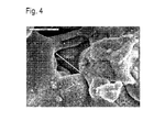
- FIG. 3 shows a sectional view of an exemplary embodiment of a pore structure 26 according to the invention.
- the material of the pore structure 26 is copper.
- the porosity is graded, d. H. it increases in the direction of 31. In particular, the porosity toward the base body 24 is smaller here than towards the outer surface 30.
- FIG. 4 shows a scanning electron micrograph of the pore structure according to FIG. 3 (magnification 3500: 1). One recognizes a pore with a pore diameter of 14 ⁇ m.
- copper pipes have been provided with a porous coating.
- the copper pipes had an outer diameter of 18 mm and a length of 350 mm.
- Tubes with the following properties were produced: pipe coating Surface roughness Ra [mm] (DIN4768) Layer thickness t c [mm] Total porosity e o [%] smooth 0.247 A Inconel 625 14.1 175.7 73.4 B 20.4 193.5 77.9 C 11.8 142.5 63.3 D copper 12.6 165.4 42.1 e 9.0 50.8 63.4
- the pore structure was produced with graded porosity.
- the column of porosity given in the table refers to the total porosity.
- FIGS. 5 (a), 5 (b) and 5 (c) show measurement results of the heat transfer coefficient as a function of the heat flux density.
- the measured values of FIG. 5 (a) were recorded for a temperature T s of 20 ° C. and a pressure P s of 572.3 kPa.
- the measured values of the graph of Fig. 5 (b) were taken at a temperature of T s of 0 ° C and a pressure P s of 292.2 kPa.
- the measured values according to FIG. 5 (c) were recorded at a temperature T s of -20 ° C. and a pressure P s of 129.9 kPa.
- the two-phase mixture (second fluid) contained tetrafluoroethane (R134a).
- the reference numeral 38 indicates the theoretical curve for a smooth tube. It can be seen that a significantly higher heat transfer coefficient can be achieved by providing a pore structure 26 (with a graded structure).
- the highest heat transfer coefficient is obtained for small heat flux densities with the tube A.
- the pipes D and E are more advantageous.
- a pore structure 26 made of copper particles it has been shown that nucleation sites of a pore size of 0.2 ⁇ m and 100 ⁇ m were formed, which are approximately homogeneously distributed in the pore structure 26.
- the smaller pores may be due to inclusions in copper and larger pores to agglomerates.
- the graded structure is made by the residual pores.
- the pore structure 26 with graded structure can basically be produced by various methods such as, for example, sintering, etching or machining by machining.
- FIG. 6 schematically shows a corresponding device.
- This device comprises a vacuum vessel 42 in which a sample 44 to be coated can be positioned.
- the sample 44 is, for example, a tube.
- the sample 44 is movably disposed in the vacuum vessel 42. In particular, it is rotatable (indicated in Figure 6 by the reference numeral 46) and longitudinally displaceable (indicated in Figure 6 by the reference numeral 48) to obtain a uniform coating of a surface 49 of the sample 44.
- a high-frequency plasma torch 50 is connected, via which a plasma jet 52 can be produced.
- the high-frequency plasma torch 50 comprises for this purpose one or more induction coils 54, by which a working gas (such as argon, helium or hydrogen) is excited for plasma formation.
- a typical excitation frequency of the induction coil 54 is 500 kHz.
- a powder material is introduced into the plasma by means of a carrier gas, such as argon. It can thereby produce a plasma jet with the powder.
- the plasma jet 52 is directed to the sample 44 to apply the coating.
- the powder can be melted onto the sample 44 to produce the pore structure 26.
- the pressure conditions during the coating of the sample 44 in the vacuum vessel 42 are typically from 80 mbar to 1 bar and preferably from 200 mbar to 300 mbar.
- the layers differ in their porosity.
- the porosity can be adjusted by adjusting different powder materials and / or different coating times and / or different speeds of the plasma jet 52. Further an adjustment of the porosity is possible via power variation of the high frequency generator and / or variation of the distance between a plasma nozzle and the sample 44 and / or pressure variation and / or gas admixtures.
- a rest time is maintained, depending on the layer thickness, before the next layer is produced successively.
- a typical magnitude of such a rest period is 2 min.
- the underlying layer is also further compressed.
- An advantage of high-frequency plasma spraying is that a large-volume plasma jet 52 can be produced which has a low radial temperature gradient.
- the velocity of the plasma jet 52 is relatively low compared to a DC plasma jet.
- the kinetic energy upon impact of molten or nearly molten powder particles on the surface of the sample 44 to be coated is relatively low.
- powders were used such as the copper powder Alpha Aeser, Lot 4323214, -155 +45 microns or commercial Inconell 625, -150 +45 microns.
- the heat transfer device may for example also be designed as a plate heat exchanger, in which case the corresponding heat transfer surface element is a heat transfer plate.
Landscapes
- Chemical & Material Sciences (AREA)
- Engineering & Computer Science (AREA)
- Physics & Mathematics (AREA)
- Mechanical Engineering (AREA)
- Plasma & Fusion (AREA)
- Chemical Kinetics & Catalysis (AREA)
- Materials Engineering (AREA)
- Metallurgy (AREA)
- Organic Chemistry (AREA)
- General Engineering & Computer Science (AREA)
- Thermal Sciences (AREA)
- Crystallography & Structural Chemistry (AREA)
- Coating By Spraying Or Casting (AREA)
- Other Surface Treatments For Metallic Materials (AREA)
- Moulds For Moulding Plastics Or The Like (AREA)
- Heating, Cooling, Or Curing Plastics Or The Like In General (AREA)
- Heat-Exchange Devices With Radiators And Conduit Assemblies (AREA)
Applications Claiming Priority (1)
| Application Number | Priority Date | Filing Date | Title |
|---|---|---|---|
| DE102006023882A DE102006023882B4 (de) | 2006-05-16 | 2006-05-16 | Wärmeübertragungsvorrichtung und Verfahren zur Herstellung einer Wärmeübertragungsvorrichtung |
Publications (2)
| Publication Number | Publication Date |
|---|---|
| EP1857764A2 true EP1857764A2 (fr) | 2007-11-21 |
| EP1857764A3 EP1857764A3 (fr) | 2013-02-20 |
Family
ID=38329581
Family Applications (1)
| Application Number | Title | Priority Date | Filing Date |
|---|---|---|---|
| EP07107709A Withdrawn EP1857764A3 (fr) | 2006-05-16 | 2007-05-08 | Dispositif de transmission de la chaleur et procédé destiné à la fabrication d'un dispositif de transmission de la chaleur |
Country Status (2)
| Country | Link |
|---|---|
| EP (1) | EP1857764A3 (fr) |
| DE (1) | DE102006023882B4 (fr) |
Families Citing this family (3)
| Publication number | Priority date | Publication date | Assignee | Title |
|---|---|---|---|---|
| DE102010030780A1 (de) * | 2010-06-30 | 2012-01-05 | Sgl Carbon Se | Wärmeübertragungselement für einen Wärmeübertrager, Verfahren zum Herstellen eines Wärmeübertragungselements für einen Wärmeübertrager, Wärmeübertrager und Nachrüstverfahren für einen Wärmeübertrager |
| DE202014003948U1 (de) * | 2014-05-13 | 2015-08-14 | Wippermann Jr. Gmbh | Rollenkette |
| DE102019214846A1 (de) * | 2019-09-27 | 2021-04-01 | Zf Friedrichshafen Ag | Plattenwärmeübertrager und Anordnung eines Plattenwärmeübertragers |
Family Cites Families (8)
| Publication number | Priority date | Publication date | Assignee | Title |
|---|---|---|---|---|
| US4663243A (en) * | 1982-10-28 | 1987-05-05 | Union Carbide Corporation | Flame-sprayed ferrous alloy enhanced boiling surface |
| US4917960A (en) * | 1983-12-29 | 1990-04-17 | Sermatech International, Inc. | Porous coated product |
| US4753849A (en) * | 1986-07-02 | 1988-06-28 | Carrier Corporation | Porous coating for enhanced tubes |
| GB8719350D0 (en) * | 1987-08-14 | 1987-09-23 | Boc Group Ltd | Heat transfer surface |
| US5018573A (en) * | 1989-12-18 | 1991-05-28 | Carrier Corporation | Method for manufacturing a high efficiency heat transfer surface and the surface so manufactured |
| US5943543A (en) * | 1993-12-27 | 1999-08-24 | Hitachi Chemical Company, Ltd. | Heat transmitting member and method of manufacturing the same |
| US6254997B1 (en) * | 1998-12-16 | 2001-07-03 | General Electric Company | Article with metallic surface layer for heat transfer augmentation and method for making |
| EP1154033A3 (fr) * | 2000-05-09 | 2003-04-23 | Deutsches Zentrum für Luft- und Raumfahrt e.V. | Element pour le transport de matières et chaleur et sa fabrication |
-
2006
- 2006-05-16 DE DE102006023882A patent/DE102006023882B4/de not_active Expired - Fee Related
-
2007
- 2007-05-08 EP EP07107709A patent/EP1857764A3/fr not_active Withdrawn
Also Published As
| Publication number | Publication date |
|---|---|
| DE102006023882B4 (de) | 2009-01-08 |
| EP1857764A3 (fr) | 2013-02-20 |
| DE102006023882A1 (de) | 2007-11-22 |
Similar Documents
| Publication | Publication Date | Title |
|---|---|---|
| DE68916383T2 (de) | Verfahren zur Herstellung eines plattierten Metallrohres. | |
| DE102013022096B4 (de) | Vorrichtung und Verfahren zum tiegelfreien Schmelzen eines Materials und zum Zerstäuben des geschmolzenen Materials zum Herstellen von Pulver | |
| DE60028034T2 (de) | Elektrode und herstellungsmethode für eine elektrode | |
| DE3880312T2 (de) | Mit Siliziumkarbid verstärkte Titan-Aluminid-Verbundwerkstoffe. | |
| DE3617055C2 (de) | Fasermaterial für Verbundmaterialien, Verfahren zu dessen Herstellung und Verwendung dieses Fasermaterials | |
| DE4408250A1 (de) | Verfahren zum Beschichten der Oberfläche eines Substrats und Beschichtungsmaterial | |
| DE69212774T2 (de) | Hitzbeständige Platte mit Kühlstruktur und Herstellungsverfahren | |
| WO2010063410A1 (fr) | Fil électrode pour découpage par électroérosion | |
| DE19915082C1 (de) | Verfahren zur Herstellung einer gekühlten Düse für ein Raketentriebwerk | |
| EP0817238B1 (fr) | Pièce moulée en aluminium et son procédé de fabrication | |
| DE19717235B4 (de) | Verfahren zur Herstellung eines Wärmerohrs | |
| WO1998033031A1 (fr) | Tube echangeur de chaleur et procede permettant de le produire | |
| WO1997050108A9 (fr) | Piece moulee en aluminium et son procede de fabrication | |
| DE69130237T2 (de) | Verfahren zur Herstellung von Kompositmaterial | |
| EP1857764A2 (fr) | Dispositif de transmission de la chaleur et procédé destiné à la fabrication d'un dispositif de transmission de la chaleur | |
| DE10050811A1 (de) | Elektronenstrahltransparentes Fenster | |
| WO1996030298A1 (fr) | Ozoniseur et procede de fabrication | |
| DE3806153C2 (de) | Verfahren zum Verbinden eines keramischen Körpers mit einem metallischen Körper | |
| DE2253915C2 (de) | Verfahren zur Herstellung vakuumdichter Verbindungen zwischen einem Keramikteil und einem Aluminiumteil und nach diesem Verfahren erhaltene Vakuumkolben | |
| DE4139421C2 (de) | Verfahren zum Überziehen einer Substratoberfläche mit einer Sinterschicht und pulverförmiges Ausgangsmaterial dafür | |
| DE1800307B1 (de) | Verfahren zur Herstellung eines metallischen Mehrschichtenverbundrohres | |
| DE102010055791A1 (de) | Verfahren zur Fertigung von Bauteilen aus Refraktärmetallen | |
| DE2227747A1 (de) | Metallkoerper mit poroeser metallauflageschicht und verfahren zu seiner herstellung | |
| DE2162699A1 (de) | Verfahren zur erhoehung der haftfestigkeit von durch thermisches spritzen aufgebrachten schichten | |
| DE10022161C1 (de) | Verfahren zum Bilden einer Oberflächenschicht und deren Verwendung |
Legal Events
| Date | Code | Title | Description |
|---|---|---|---|
| PUAI | Public reference made under article 153(3) epc to a published international application that has entered the european phase |
Free format text: ORIGINAL CODE: 0009012 |
|
| AK | Designated contracting states |
Kind code of ref document: A2 Designated state(s): AT BE BG CH CY CZ DE DK EE ES FI FR GB GR HU IE IS IT LI LT LU LV MC MT NL PL PT RO SE SI SK TR |
|
| AX | Request for extension of the european patent |
Extension state: AL BA HR MK YU |
|
| PUAL | Search report despatched |
Free format text: ORIGINAL CODE: 0009013 |
|
| AK | Designated contracting states |
Kind code of ref document: A3 Designated state(s): AT BE BG CH CY CZ DE DK EE ES FI FR GB GR HU IE IS IT LI LT LU LV MC MT NL PL PT RO SE SI SK TR |
|
| AX | Request for extension of the european patent |
Extension state: AL BA HR MK RS |
|
| RIC1 | Information provided on ipc code assigned before grant |
Ipc: F28F 13/18 20060101AFI20130117BHEP Ipc: C23C 4/12 20060101ALI20130117BHEP |
|
| AKY | No designation fees paid | ||
| REG | Reference to a national code |
Ref country code: DE Ref legal event code: R108 |
|
| REG | Reference to a national code |
Ref country code: DE Ref legal event code: R108 Effective date: 20131023 |
|
| STAA | Information on the status of an ep patent application or granted ep patent |
Free format text: STATUS: THE APPLICATION IS DEEMED TO BE WITHDRAWN |
|
| 18D | Application deemed to be withdrawn |
Effective date: 20130821 |