EP1857766B1 - Raketenwerfer - Google Patents
Raketenwerfer Download PDFInfo
- Publication number
- EP1857766B1 EP1857766B1 EP06114163A EP06114163A EP1857766B1 EP 1857766 B1 EP1857766 B1 EP 1857766B1 EP 06114163 A EP06114163 A EP 06114163A EP 06114163 A EP06114163 A EP 06114163A EP 1857766 B1 EP1857766 B1 EP 1857766B1
- Authority
- EP
- European Patent Office
- Prior art keywords
- missile
- roll member
- launcher
- roll
- support
- Prior art date
- Legal status (The legal status is an assumption and is not a legal conclusion. Google has not performed a legal analysis and makes no representation as to the accuracy of the status listed.)
- Expired - Lifetime
Links
Images



Classifications
-
- F—MECHANICAL ENGINEERING; LIGHTING; HEATING; WEAPONS; BLASTING
- F41—WEAPONS
- F41F—APPARATUS FOR LAUNCHING PROJECTILES OR MISSILES FROM BARRELS, e.g. CANNONS; LAUNCHERS FOR ROCKETS OR TORPEDOES; HARPOON GUNS
- F41F3/00—Rocket or torpedo launchers
- F41F3/04—Rocket or torpedo launchers for rockets
- F41F3/052—Means for securing the rocket in the launching apparatus
Definitions
- the present invention refers to a missile launcher according to the precharacterising portion of claim 1.
- a missile launcher The function of a missile launcher is twofold. It should provide support for the missile before launch and at the first portion of the launch run. Support could be provided by support means. It should also clear away said support means in a controlled way so that they do not collide or otherwise interfere adversely with the missile during the continued launching run.
- Such a launcher is known from GB 871024 , which is considered to be the closest prior art.
- the document discloses a missile launcher supporting a missile by a first support at a front end, and by a second support at an aft end.
- the first support is arranged to swing clear of the aft portion of the missile during the initial period of its launching run.
- the missile is provided with a guide rail and a trip member to cooperate with a roll on the first support during the initial period of launching, in that the striking of the trip member against the roll when the missile is passing causes the support to swing clear of the missile.
- the above object is solved by a missile launcher according to claim 1.
- the missile launcher comprises a forward support for supporting a forward portion of a missile, and an aft support for supporting an aft portion of the missile where the forward support is arranged to swing clear of the aft portion of the missile during the initial period of its launching run
- the forward support comprises a support member being in the shape of a segment of a circle and pivoted at the circle centre, where the perimeter of said member is arranged to make frictional contact to the missile fuselage in order to confer mechanical energy from the missile to the support member to make said member to swing clear of the aft portion of the missile during the initial period of said missiles launching run.
- the missile launcher where said first support comprises at least one support member.
- the first support may comprise two or, most preferred, four support members, evenly spaced around the missile body.
- the missile launcher where further a prestressing force adjustment mechanism is arranged to make it possible to create and adjust an initial force of a support member towards the missile fuselage.
- the missile launcher where the perimeter surface of the support member has a concave shape enabling a larger contact surface to the missile fuselage, and/or is provided with a friction enhancing material, such as rubber.
- a problem with prior art missile launchers is that they are unsuitable to launch missiles that are provided with an even surface. As missile velocity increases it is more and more important to provide the missile with a smooth, aerodynamic shape. It may also be important to provide the missile with heat shielding, and/or a heat resistant shape, i.e., a shape that do not give rise to, or transfer frictional heat to the inside of the missile. The result of such aerodynamic and heat resistant design is often a very smooth missile body shape. There is thus a need for missile launchers capable of handling such missiles in an efficient way.
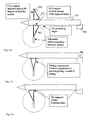
- Fig. 1-4 is sketches showing the principle of a missile launcher according to prior art.
- a missile body 10 having a guide rail 22 and a trip member 23 to cooperate with a roll 24 on the first support 19 during the initial period of launching, in that the striking of the trip member 23 against the roll 24 when the missile is passing causes the support 19 to swing clear of the missile.
- Fig. 5 shows the launcher and missile 510 in a resting position before the launching run is started.
- the missile 510 is resting upon an aft sliding support 505, supporting an aft end of the missile 510.
- a front portion of the missile 510 is supported by four front supports 501, 502.
- the front supports are arranged to support the missile and prevent it from diverting to the right, to the left, upwards, and downwards.
- each front support comprises a sector-shaped roll member 501 having a curved surface 521 arranged to make contact to the surface of the front portion of the body of the missile.
- the roll member 501 is hinged at a center point such that the curved surface can roll on the missile body as would a part of a wheel.
- the curved surface 521 may be faced with a friction enhancing material, e.g. rubber, to ensure that the frictional force, i.e. the prestressing force of the support multiplied with the friction coefficient, created between the roll member 501 and the missile body is great enough to apply enough torque to the roll member to clear away the roll member 501 before the aft portion of the missile passes.
- a friction enhancing material e.g. rubber
- the roll member 501 is prevented from rotating backwards by means of a back stop 615.
- a heel 506 on the aft sliding support 505 prevents the missile from sliding backwards.
- a roll member 501 and the aft sliding support 505 are arranged having a missile contact zone of corresponding length such that the missile leaves the roll member 501 and the aft sliding support 505 at the same time.
- missile contact zone is meant the length of a portion of a support that makes contact to the missile during any time of its launching run.
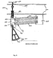
- roll member 601 is preferably arranged in a correct position by means of an outer frame 660.
- the roll member 601 is rotatably attached to a guiding piece 610, said piece 610 being guided to only being able to move in a single direction, in this case up-down.
- the movement can be said to take place in a direction perpendicular to a length axis of the missile.
- the guiding piece 610 is stabilised and guided by two parallel slewing brackets 620, 621, said brackets pivoting at their first ends at the guiding piece 610 and at their second ends at a socket 625 attached to the frame 660.
- the guiding piece is also connected by means of a hinged connection to a prestressing force adjustment mechanism 670, making it possible to adjust the position and prestressing force of the roll member by means of a adjustment screw 635 and a pressure spring 630.
- the prestressing force adjustment mechanism 670 is further provided with a rotatable joint between a handle 634 and the spring 630.
- the perimeter surface of the support member may have a concave shape enabling a larger contact surface to the missile fuselage than would a flat one.
- Fig. 7a is a side view showing the location of a catching device 700 and a roll member of the front support of fig. 6 .
- the catching device 700 is arranged on the frame such that when the roll member 601 swing during launch, it will swing such that a portion of said roll member 601 will come into contact and becomes withheld by said catching device 700.
- Fig. 7b is a view showing the roll member and catching device of fig. 7a in a pre launch position.
- the catching device 700 comprises a first and a second arm 705, 706 with opposing surfaces 710, 711. Said surfaces is preferably covered with a friction enhancing material, e.g. rubber.
- the arms 705, 706 and surfaces 710, 711 are arranged such that a tapering slot is formed. The taper angle is designed such that the taper together with the roll member becomes self locking.
- one or more leaf springs 720, 721 can be arranged to catch the roll member 601 at its end position.
- the leaf springs 720, 721 are arranged to spring back and let the roll member pass when swinging forward, but to cooperate with fenestrations 703 and/or ribs or edges of the roll member 601 to prevent said roll member from swinging backwards.
- the fenestrations 702, 703, 704 will also have the function of providing a more lightweight roll member 601.
- An advantage of a missile launcher according to the present invention is that there is no need for any engaging means such as guide rail or trip members on the missile body.
- a further advantage with the missile launcher described above is that the launcher does not need any external power source to be able to clear away the roll members 501-504. They simply receive their momentum from the missile when said missile is launched.
- the launcher is able to handle dimension differences due to tolerances effectively with the aid of the adjustable pressure springs of the prestressing force adjustment mechanism 670.
- the resilient mounting of the roll members 501,502 may also provide reduction of vibrations during transport.
- the launcher offers a possibility to adjust friction and prestress for those cases when one of them are critical. If low prestress is desired, more friction is needed, and vice versa.
Landscapes
- Engineering & Computer Science (AREA)
- General Engineering & Computer Science (AREA)
- Aiming, Guidance, Guns With A Light Source, Armor, Camouflage, And Targets (AREA)
- Toys (AREA)
- Steroid Compounds (AREA)
- Organic Low-Molecular-Weight Compounds And Preparation Thereof (AREA)
Claims (7)
- Ein Raketenwerfer, der eine vordere Auflage zur Abstützung eines vorderen Teils einer Rakete (510) und eine hintere Auflage (505) zur Abstützung eines hinteren Teils der Rakete (510) aufweist, wobei die vordere Anlage so ausgeführt ist, dass sie von dem hinteren Teil der Rakete (510) während der Anfangsperiode des Startverlaufs freischwenkt, dadurch gekennzeichnet, dass die vordere Auflage ein Walzenelement (501, 601) in Form eines Segments eines Kreises, das in der Kreismitte drehbar ist, ausweist, wobei der Umfang (602) des genannten Elements (501, 601) Reibungskontakt mit dem Rumpf der Rakete aufweist, um mechanische Energie auf das Walzenelement (501, 601) zu übertragen, sodass das genannte Element von dem hinteren Teil der Rakete (510) während der Anfangsperiode des Startverlaufs der genannten Rakete freischwenkt.
- Der Raketenwerfer gemäß Anspruch 1, wobei die vordere Auflage mindestens ein Walzenelement (501, 502, 601) aufweist.
- Der Raketenwerfer gemäß Anspruch 1, wobei die vordere Auflage mindestens zwei Walzenelemente (501, 502, 601) auf den gegenüberliegenden Seiten des Raketenkörpers aufweist.
- Der Raketenwerfer gemäß Anspruch 1, wobei die vordere Auflage vier Walzenelemente (501, 502, 601) gleichmäßig um den Raketenkörper verteilt aufweist.
- Der Raketenwerfer gemäß der Ansprüche 1 bis 4, wobei eine Vorspanneinrichtung (670) zur Krafteinstellung das Erstellen und Einstellen einer initialen Kraft eines Walzenelements (501, 601) an dem Rumpf der Rakete ermöglicht.
- Der Raketenwerfer gemäß eines der vorhergehenden Ansprüche, wobei die Umfangsoberfläche des Walzenelementes (501, 601) eine konkave Form aufweist, die eine größere Anlagefläche an dem Rumpf der Rakete ermöglicht.
- Der Raketenwerfer gemäß eines der vorhergehenden Ansprüche, wobei eine Fanganordnung (700) am Schwenkende des Walzenelements (501, 601) angeordnet ist, um das Zurückspringen des genannten Walzenelements (501, 601) und die Behinderung der Abschussrakete (510) zu verhindern.
Priority Applications (7)
| Application Number | Priority Date | Filing Date | Title |
|---|---|---|---|
| EP06114163A EP1857766B1 (de) | 2006-05-18 | 2006-05-18 | Raketenwerfer |
| DE602006007687T DE602006007687D1 (de) | 2006-05-18 | 2006-05-18 | Raketenwerfer |
| ES06114163T ES2329500T3 (es) | 2006-05-18 | 2006-05-18 | Lanzamisiles. |
| AT06114163T ATE436003T1 (de) | 2006-05-18 | 2006-05-18 | Raketenwerfer |
| IL182862A IL182862A (en) | 2006-05-18 | 2007-04-30 | Missile launcher |
| ZA200703886A ZA200703886B (en) | 2006-05-18 | 2007-05-14 | Missile launcher |
| US11/802,030 US7690289B2 (en) | 2006-05-18 | 2007-05-18 | Missile launcher |
Applications Claiming Priority (1)
| Application Number | Priority Date | Filing Date | Title |
|---|---|---|---|
| EP06114163A EP1857766B1 (de) | 2006-05-18 | 2006-05-18 | Raketenwerfer |
Publications (2)
| Publication Number | Publication Date |
|---|---|
| EP1857766A1 EP1857766A1 (de) | 2007-11-21 |
| EP1857766B1 true EP1857766B1 (de) | 2009-07-08 |
Family
ID=37076044
Family Applications (1)
| Application Number | Title | Priority Date | Filing Date |
|---|---|---|---|
| EP06114163A Expired - Lifetime EP1857766B1 (de) | 2006-05-18 | 2006-05-18 | Raketenwerfer |
Country Status (7)
| Country | Link |
|---|---|
| US (1) | US7690289B2 (de) |
| EP (1) | EP1857766B1 (de) |
| AT (1) | ATE436003T1 (de) |
| DE (1) | DE602006007687D1 (de) |
| ES (1) | ES2329500T3 (de) |
| IL (1) | IL182862A (de) |
| ZA (1) | ZA200703886B (de) |
Families Citing this family (4)
| Publication number | Priority date | Publication date | Assignee | Title |
|---|---|---|---|---|
| KR101755463B1 (ko) * | 2015-06-18 | 2017-07-07 | 현대자동차 주식회사 | 차량 연소음 마스킹 제어 장치 및 방법 |
| CN106289690B (zh) * | 2016-07-29 | 2018-11-27 | 江西洪都航空工业集团有限责任公司 | 一种振动试验夹具 |
| JP7129285B2 (ja) * | 2018-09-07 | 2022-09-01 | 三菱重工業株式会社 | 発射筒及び飛しょう体の発射方法 |
| RU193719U1 (ru) * | 2019-08-13 | 2019-11-11 | Акционерное общество "Научно-производственная корпорация "Конструкторское бюро машиностроения" | Пусковая установка зенитных ракет индивидуального пользования |
Family Cites Families (7)
| Publication number | Priority date | Publication date | Assignee | Title |
|---|---|---|---|---|
| US2843020A (en) * | 1953-06-22 | 1958-07-15 | Northrop Aircraft Inc | Zero-length launcher |
| GB871024A (en) | 1957-08-02 | 1961-06-21 | Bristol Aerojet Ltd | Improvements relating to the launching of aerial vehicles |
| FR1260965A (fr) * | 1959-06-19 | 1961-05-12 | Contraves Ag | Procédé de lancement oblique d'une roquette à partir d'une plate-forme, et dispositif auxiliaire de lancement permettant d'appliquer ce procédé |
| FR1297179A (fr) * | 1961-05-15 | 1962-06-29 | Emballage pour engins autopropulsés | |
| US3301132A (en) * | 1965-07-29 | 1967-01-31 | Guenther W Lehmann | Submersible missile launching vehicle |
| US3437285A (en) * | 1966-08-04 | 1969-04-08 | Dario Manfredi | Space vehicle and launching means therefor |
| US3584532A (en) * | 1969-09-16 | 1971-06-15 | Oberlikon Buehrle Holding Ag Z | Automatic gun with ejection actuated rammer |
-
2006
- 2006-05-18 EP EP06114163A patent/EP1857766B1/de not_active Expired - Lifetime
- 2006-05-18 AT AT06114163T patent/ATE436003T1/de not_active IP Right Cessation
- 2006-05-18 ES ES06114163T patent/ES2329500T3/es not_active Expired - Lifetime
- 2006-05-18 DE DE602006007687T patent/DE602006007687D1/de not_active Expired - Lifetime
-
2007
- 2007-04-30 IL IL182862A patent/IL182862A/en active IP Right Grant
- 2007-05-14 ZA ZA200703886A patent/ZA200703886B/xx unknown
- 2007-05-18 US US11/802,030 patent/US7690289B2/en not_active Expired - Fee Related
Also Published As
| Publication number | Publication date |
|---|---|
| DE602006007687D1 (de) | 2009-08-20 |
| IL182862A0 (en) | 2007-09-20 |
| ZA200703886B (en) | 2008-06-25 |
| US7690289B2 (en) | 2010-04-06 |
| IL182862A (en) | 2011-06-30 |
| ES2329500T3 (es) | 2009-11-26 |
| EP1857766A1 (de) | 2007-11-21 |
| ATE436003T1 (de) | 2009-07-15 |
| US20090188382A1 (en) | 2009-07-30 |
Similar Documents
| Publication | Publication Date | Title |
|---|---|---|
| US4457288A (en) | Cam lever compound bow | |
| US9303946B2 (en) | Swivel cable guard | |
| US10190841B2 (en) | Fixed axle compound crossbow | |
| US10520274B2 (en) | Crossbow assembly | |
| US10907925B2 (en) | Crossbow power cable support | |
| US9273921B2 (en) | Archery bow, floating limb compound (FLC) | |
| US8136514B2 (en) | Device for propelling a projectile | |
| US10502516B2 (en) | Crossbow cam | |
| US8899218B2 (en) | Shooting bow | |
| US10240890B2 (en) | Stock for crossbow or gun | |
| US7963279B2 (en) | Drop-away arrow rest | |
| US7690289B2 (en) | Missile launcher | |
| US20190178603A1 (en) | Fixed axle compound crossbow and method for operating a crossbow | |
| US20100116260A1 (en) | Titlting limb system for bows and crossbows and equipment formed therewith | |
| US6957644B2 (en) | Mechanical release or trigger device | |
| US9568271B2 (en) | “Trolley” arm bow attachment for lofting an arrow above its line of sight to a target | |
| US11221190B2 (en) | Torque reducing apparatus and method | |
| US9140281B1 (en) | Bisynchronous compound bow with no limb-pulley torque and enhanced limb energy storage | |
| EP0679856A1 (de) | Abzugsmechanismus für ein kleinkaliber automatische Waffe | |
| WO1995010748A1 (en) | Finless aerodynamic control system | |
| US10746499B2 (en) | Tapered arrow launcher | |
| US10845154B2 (en) | Archery release device | |
| US8960173B2 (en) | Compound bow with rigid deflecting stop | |
| US20200208939A1 (en) | Pivoting limb pad assembly for an archery bow | |
| US6402087B1 (en) | Fixed canards maneuverability enhancement |
Legal Events
| Date | Code | Title | Description |
|---|---|---|---|
| PUAI | Public reference made under article 153(3) epc to a published international application that has entered the european phase |
Free format text: ORIGINAL CODE: 0009012 |
|
| AK | Designated contracting states |
Kind code of ref document: A1 Designated state(s): AT BE BG CH CY CZ DE DK EE ES FI FR GB GR HU IE IS IT LI LT LU LV MC NL PL PT RO SE SI SK TR |
|
| AX | Request for extension of the european patent |
Extension state: AL BA HR MK YU |
|
| 17P | Request for examination filed |
Effective date: 20080509 |
|
| AKX | Designation fees paid |
Designated state(s): AT BE BG CH CY CZ DE DK EE ES FI FR GB GR HU IE IS IT LI LT LU LV MC NL PL PT RO SE SI SK TR |
|
| GRAP | Despatch of communication of intention to grant a patent |
Free format text: ORIGINAL CODE: EPIDOSNIGR1 |
|
| GRAS | Grant fee paid |
Free format text: ORIGINAL CODE: EPIDOSNIGR3 |
|
| GRAA | (expected) grant |
Free format text: ORIGINAL CODE: 0009210 |
|
| AK | Designated contracting states |
Kind code of ref document: B1 Designated state(s): AT BE BG CH CY CZ DE DK EE ES FI FR GB GR HU IE IS IT LI LT LU LV MC NL PL PT RO SE SI SK TR |
|
| REG | Reference to a national code |
Ref country code: GB Ref legal event code: FG4D |
|
| REG | Reference to a national code |
Ref country code: CH Ref legal event code: EP |
|
| REG | Reference to a national code |
Ref country code: IE Ref legal event code: FG4D |
|
| REF | Corresponds to: |
Ref document number: 602006007687 Country of ref document: DE Date of ref document: 20090820 Kind code of ref document: P |
|
| REG | Reference to a national code |
Ref country code: ES Ref legal event code: FG2A Ref document number: 2329500 Country of ref document: ES Kind code of ref document: T3 |
|
| PG25 | Lapsed in a contracting state [announced via postgrant information from national office to epo] |
Ref country code: SI Free format text: LAPSE BECAUSE OF FAILURE TO SUBMIT A TRANSLATION OF THE DESCRIPTION OR TO PAY THE FEE WITHIN THE PRESCRIBED TIME-LIMIT Effective date: 20090708 |
|
| NLV1 | Nl: lapsed or annulled due to failure to fulfill the requirements of art. 29p and 29m of the patents act | ||
| PG25 | Lapsed in a contracting state [announced via postgrant information from national office to epo] |
Ref country code: LT Free format text: LAPSE BECAUSE OF FAILURE TO SUBMIT A TRANSLATION OF THE DESCRIPTION OR TO PAY THE FEE WITHIN THE PRESCRIBED TIME-LIMIT Effective date: 20090708 Ref country code: FI Free format text: LAPSE BECAUSE OF FAILURE TO SUBMIT A TRANSLATION OF THE DESCRIPTION OR TO PAY THE FEE WITHIN THE PRESCRIBED TIME-LIMIT Effective date: 20090708 Ref country code: IS Free format text: LAPSE BECAUSE OF FAILURE TO SUBMIT A TRANSLATION OF THE DESCRIPTION OR TO PAY THE FEE WITHIN THE PRESCRIBED TIME-LIMIT Effective date: 20091108 Ref country code: AT Free format text: LAPSE BECAUSE OF FAILURE TO SUBMIT A TRANSLATION OF THE DESCRIPTION OR TO PAY THE FEE WITHIN THE PRESCRIBED TIME-LIMIT Effective date: 20090708 |
|
| PG25 | Lapsed in a contracting state [announced via postgrant information from national office to epo] |
Ref country code: PL Free format text: LAPSE BECAUSE OF FAILURE TO SUBMIT A TRANSLATION OF THE DESCRIPTION OR TO PAY THE FEE WITHIN THE PRESCRIBED TIME-LIMIT Effective date: 20090708 Ref country code: NL Free format text: LAPSE BECAUSE OF FAILURE TO SUBMIT A TRANSLATION OF THE DESCRIPTION OR TO PAY THE FEE WITHIN THE PRESCRIBED TIME-LIMIT Effective date: 20090708 Ref country code: LV Free format text: LAPSE BECAUSE OF FAILURE TO SUBMIT A TRANSLATION OF THE DESCRIPTION OR TO PAY THE FEE WITHIN THE PRESCRIBED TIME-LIMIT Effective date: 20090708 |
|
| PG25 | Lapsed in a contracting state [announced via postgrant information from national office to epo] |
Ref country code: PT Free format text: LAPSE BECAUSE OF FAILURE TO SUBMIT A TRANSLATION OF THE DESCRIPTION OR TO PAY THE FEE WITHIN THE PRESCRIBED TIME-LIMIT Effective date: 20091109 Ref country code: BG Free format text: LAPSE BECAUSE OF FAILURE TO SUBMIT A TRANSLATION OF THE DESCRIPTION OR TO PAY THE FEE WITHIN THE PRESCRIBED TIME-LIMIT Effective date: 20091008 |
|
| PG25 | Lapsed in a contracting state [announced via postgrant information from national office to epo] |
Ref country code: EE Free format text: LAPSE BECAUSE OF FAILURE TO SUBMIT A TRANSLATION OF THE DESCRIPTION OR TO PAY THE FEE WITHIN THE PRESCRIBED TIME-LIMIT Effective date: 20090708 Ref country code: DK Free format text: LAPSE BECAUSE OF FAILURE TO SUBMIT A TRANSLATION OF THE DESCRIPTION OR TO PAY THE FEE WITHIN THE PRESCRIBED TIME-LIMIT Effective date: 20090708 Ref country code: RO Free format text: LAPSE BECAUSE OF FAILURE TO SUBMIT A TRANSLATION OF THE DESCRIPTION OR TO PAY THE FEE WITHIN THE PRESCRIBED TIME-LIMIT Effective date: 20090708 Ref country code: CZ Free format text: LAPSE BECAUSE OF FAILURE TO SUBMIT A TRANSLATION OF THE DESCRIPTION OR TO PAY THE FEE WITHIN THE PRESCRIBED TIME-LIMIT Effective date: 20090708 |
|
| PLBE | No opposition filed within time limit |
Free format text: ORIGINAL CODE: 0009261 |
|
| STAA | Information on the status of an ep patent application or granted ep patent |
Free format text: STATUS: NO OPPOSITION FILED WITHIN TIME LIMIT |
|
| PG25 | Lapsed in a contracting state [announced via postgrant information from national office to epo] |
Ref country code: SK Free format text: LAPSE BECAUSE OF FAILURE TO SUBMIT A TRANSLATION OF THE DESCRIPTION OR TO PAY THE FEE WITHIN THE PRESCRIBED TIME-LIMIT Effective date: 20090708 Ref country code: BE Free format text: LAPSE BECAUSE OF FAILURE TO SUBMIT A TRANSLATION OF THE DESCRIPTION OR TO PAY THE FEE WITHIN THE PRESCRIBED TIME-LIMIT Effective date: 20090708 |
|
| 26N | No opposition filed |
Effective date: 20100409 |
|
| PG25 | Lapsed in a contracting state [announced via postgrant information from national office to epo] |
Ref country code: GR Free format text: LAPSE BECAUSE OF FAILURE TO SUBMIT A TRANSLATION OF THE DESCRIPTION OR TO PAY THE FEE WITHIN THE PRESCRIBED TIME-LIMIT Effective date: 20091009 |
|
| PG25 | Lapsed in a contracting state [announced via postgrant information from national office to epo] |
Ref country code: MC Free format text: LAPSE BECAUSE OF NON-PAYMENT OF DUE FEES Effective date: 20100531 |
|
| REG | Reference to a national code |
Ref country code: CH Ref legal event code: PL |
|
| PG25 | Lapsed in a contracting state [announced via postgrant information from national office to epo] |
Ref country code: CH Free format text: LAPSE BECAUSE OF NON-PAYMENT OF DUE FEES Effective date: 20100531 Ref country code: LI Free format text: LAPSE BECAUSE OF NON-PAYMENT OF DUE FEES Effective date: 20100531 |
|
| PG25 | Lapsed in a contracting state [announced via postgrant information from national office to epo] |
Ref country code: IE Free format text: LAPSE BECAUSE OF NON-PAYMENT OF DUE FEES Effective date: 20100518 |
|
| PG25 | Lapsed in a contracting state [announced via postgrant information from national office to epo] |
Ref country code: CY Free format text: LAPSE BECAUSE OF FAILURE TO SUBMIT A TRANSLATION OF THE DESCRIPTION OR TO PAY THE FEE WITHIN THE PRESCRIBED TIME-LIMIT Effective date: 20090708 |
|
| PG25 | Lapsed in a contracting state [announced via postgrant information from national office to epo] |
Ref country code: SE Free format text: LAPSE BECAUSE OF FAILURE TO SUBMIT A TRANSLATION OF THE DESCRIPTION OR TO PAY THE FEE WITHIN THE PRESCRIBED TIME-LIMIT Effective date: 20090708 Ref country code: LU Free format text: LAPSE BECAUSE OF NON-PAYMENT OF DUE FEES Effective date: 20100518 Ref country code: HU Free format text: LAPSE BECAUSE OF FAILURE TO SUBMIT A TRANSLATION OF THE DESCRIPTION OR TO PAY THE FEE WITHIN THE PRESCRIBED TIME-LIMIT Effective date: 20100109 |
|
| PG25 | Lapsed in a contracting state [announced via postgrant information from national office to epo] |
Ref country code: TR Free format text: LAPSE BECAUSE OF FAILURE TO SUBMIT A TRANSLATION OF THE DESCRIPTION OR TO PAY THE FEE WITHIN THE PRESCRIBED TIME-LIMIT Effective date: 20090708 |
|
| REG | Reference to a national code |
Ref country code: FR Ref legal event code: PLFP Year of fee payment: 11 |
|
| REG | Reference to a national code |
Ref country code: FR Ref legal event code: PLFP Year of fee payment: 12 |
|
| REG | Reference to a national code |
Ref country code: FR Ref legal event code: PLFP Year of fee payment: 13 |
|
| PGFP | Annual fee paid to national office [announced via postgrant information from national office to epo] |
Ref country code: IT Payment date: 20190528 Year of fee payment: 14 Ref country code: DE Payment date: 20190520 Year of fee payment: 14 Ref country code: ES Payment date: 20190604 Year of fee payment: 14 |
|
| PGFP | Annual fee paid to national office [announced via postgrant information from national office to epo] |
Ref country code: FR Payment date: 20190520 Year of fee payment: 14 |
|
| PGFP | Annual fee paid to national office [announced via postgrant information from national office to epo] |
Ref country code: GB Payment date: 20190520 Year of fee payment: 14 |
|
| REG | Reference to a national code |
Ref country code: DE Ref legal event code: R119 Ref document number: 602006007687 Country of ref document: DE |
|
| GBPC | Gb: european patent ceased through non-payment of renewal fee |
Effective date: 20200518 |
|
| PG25 | Lapsed in a contracting state [announced via postgrant information from national office to epo] |
Ref country code: FR Free format text: LAPSE BECAUSE OF NON-PAYMENT OF DUE FEES Effective date: 20200531 Ref country code: GB Free format text: LAPSE BECAUSE OF NON-PAYMENT OF DUE FEES Effective date: 20200518 |
|
| PG25 | Lapsed in a contracting state [announced via postgrant information from national office to epo] |
Ref country code: DE Free format text: LAPSE BECAUSE OF NON-PAYMENT OF DUE FEES Effective date: 20201201 |
|
| REG | Reference to a national code |
Ref country code: ES Ref legal event code: FD2A Effective date: 20210930 |
|
| PG25 | Lapsed in a contracting state [announced via postgrant information from national office to epo] |
Ref country code: IT Free format text: LAPSE BECAUSE OF NON-PAYMENT OF DUE FEES Effective date: 20200518 |
|
| PG25 | Lapsed in a contracting state [announced via postgrant information from national office to epo] |
Ref country code: ES Free format text: LAPSE BECAUSE OF NON-PAYMENT OF DUE FEES Effective date: 20200519 |